- Title Page
- Introduction to the FireSIGHT System
- Deploying on a Management Network
- Deploying Managed Devices
- Installing a FireSIGHT System Appliance
- Setting Up a FireSIGHT System Appliance
- Using the LCD Panel on a Series 3 Device
- Hardware Specifications
- Restoring a FireSIGHT System Appliance to Factory Defaults
- Power Requirements for FirePOWER Devices
- Using SFP Transceivers in 3D71x5 and AMP7150 Devices
- Inserting and Removing 8000 Series Modules
- Scrubbing the Hard Drive
- Preconfiguring FireSIGHT System Appliances
- Glossary
- Sensing Deployment Considerations
- Understanding Sensing Interfaces
- Connecting Devices to Your Network
- Deployment Options
Deploying Managed Devices
After you register your device to a Defense Center, you deploy the sensing interfaces of your managed device on a network segment to monitor traffic using an intrusion detection system or protect your network from threats using an intrusion prevention system.
For sensing deployment information, see the following sections:
- Sensing Deployment Considerations
- Understanding Sensing Interfaces
- Connecting Devices to Your Network
- Deployment Options
- Using Multiple Sensing Interfaces on a Managed Device
- Complex Network Deployments

Note![]() See the ASA documentation for more information on deployment scenarios for ASA FirePOWER devices.
See the ASA documentation for more information on deployment scenarios for ASA FirePOWER devices.
For additional information about deployments, consult the Best Practices Guide , available from the Cisco sales department.
Sensing Deployment Considerations
Your sensing deployment decisions will be based on a variety of factors. Answering these questions can help you understand the vulnerable areas of your network and clarify your intrusion detection and prevention needs:
- Will you be deploying your managed device with passive or inline interfaces? Does your device support a mix of interfaces, some passive and others inline? See Understanding Sensing Interfaces for more information.
- How will you connect the managed devices to the network? Hubs? Taps? Spanning ports on switches? Virtual switches? See Connecting Devices to Your Network for more information.
- Do you want to detect every attack on your network, or do you only want to know about attacks that penetrate your firewall? Do you have specific assets on your network such as financial, accounting, or personnel records, production code, or other sensitive, protected information that require special security policies? See Deployment Options for more information.
- Will you use multiple sensing interfaces on your managed device to recombine the separate connections from a network tap, or to capture and evaluate traffic from different networks? Do you want to use the multiple sensing interfaces to perform as a virtual router or a virtual switch? See Using Multiple Sensing Interfaces on a Managed Device for more information.
- Do you provide VPN or modem access for remote workers? Do you have remote offices that also require an intrusion protection deployment? Do you employ contractors or other temporary employees? Are they restricted to specific network segments? Do you integrate your network with the networks of other organizations such as customers, suppliers, or business partners? See Complex Network Deployments for more information.
Understanding Sensing Interfaces
The sections that follow describe how different sensing interfaces affect the capabilities of the FireSIGHT System. In addition to passive and inline interfaces, you can also have routed, switched, and hybrid interfaces.
Sensing interfaces are located on the front of the device. To identify your sensing interfaces, see Identifying the Sensing Interfaces. To learn more about sensing interfaces, see the following sections for more information:
Passive Interfaces
You can configure a passive deployment to monitor traffic flowing across a network using a switch SPAN, virtual switch, or mirror port, allowing traffic to be copied from other ports on the switch. Passive interfaces allow you to inspect traffic within the network without being in the flow of network traffic. When configured in a passive deployment, the system cannot take certain actions such as blocking or shaping traffic. Passive interfaces receive all traffic unconditionally and do not retransmit received traffic.
You can configure one or more physical ports on a managed device as passive interfaces. For more information, see Connecting Devices to Your Network. For information on configuring an ASA FirePOWER device in passive mode, see the ASA documentation.
Inline Interfaces
You configure an inline deployment transparently on a network segment by binding two ports together. Inline interfaces allow you to install a device in any network configuration without the configuration of adjacent network devices. Inline interfaces receive all traffic unconditionally, then retransmit all traffic received on these interfaces except traffic explicitly dropped.
You can configure one or more physical ports on a managed device as inline interfaces. You must assign a pair of inline interfaces to an inline set before they can handle traffic in an inline deployment.
Note![]() If you configure an interface as an inline interface, the adjacent port on its NetMod automatically becomes an inline interface as well to complete the pair.
If you configure an interface as an inline interface, the adjacent port on its NetMod automatically becomes an inline interface as well to complete the pair.
Configurable bypass inline sets allow you to select how your traffic is handled if your hardware fails completely (for example, the device loses power). You may determine that connectivity is critical on one network segment, and, on another network segment, you cannot permit uninspected traffic. Using configurable bypass inline sets, you can manage the traffic flow of your network traffic in one of the following ways:
- Bypass : an interface pair configured for bypass allows all traffic to flow if the device fails. The traffic bypasses the device and any inspection or other processing by the device. Bypass allows uninspected traffic across the network segment, but ensures that the network connectivity is maintained.
- Non-bypass : an interface pair configured for non-bypass stops all traffic if the device fails. Traffic that reaches the failed device does not enter the device. Non-bypass does not permit traffic to pass uninspected, but the network segment loses connectivity if the device fails. Use non-bypass interfaces in deployment situations where network security is more important than loss of traffic.
Configure the inline set as bypass to ensure that traffic continues to flow if your device fails. Configure the inline set as non-bypass to stop traffic if the device fails. Note that reimaging resets appliances in bypass mode to a non-bypass configuration and disrupts traffic on your network until you reconfigure bypass mode. For more information, see Traffic Flow During the Restore Process.
All appliances can contain configurable bypass interfaces. The 8000 Series appliances can also contain NetMods with interfaces that cannot be configured for bypass. For more information on NetMods, see 8000 Series Modules.
Advanced options vary by appliance and can include tap mode, propagate link state, transparent inline mode, and strict TCP mode. For information on how to configure your inline interface sets, see Configuring Inline Sets in the FireSIGHT System User Guide . For more information on using inline interfaces, see Connecting Devices to Your Network.
You cannot configure bypass interfaces on an ASA FirePOWER device using the FireSIGHT System. For information on configuring an ASA FirePOWER device in inline mode, see the ASA documentation.
Switched Interfaces
You can configure switched interfaces on a managed device in a Layer 2 deployment to provide packet switching between two or more networks. You can also configure virtual switches on managed devices to operate as standalone broadcast domains, dividing your network into logical segments. A virtual switch uses the media access control (MAC) address from a host to determine where to send packets.
Switched interfaces can have either a physical or logical configuration:
- Physical switched interfaces are physical interfaces with switching configured. Use physical switched interfaces to handle untagged VLAN traffic.
- Logical switched interfaces are an association between a physical interface and a VLAN tag. Use logical interfaces to handle traffic with designated VLAN tags.
Virtual switches can operate as standalone broadcast domains, dividing your network into logical segments. A virtual switch uses the media access control (MAC) address from a host to determine where to send packets. When you configure a virtual switch, the switch initially broadcasts packets through every available port on the switch. Over time, the switch uses tagged return traffic to learn which hosts reside on the networks connected to each port.
You can configure your device as a virtual switch and use the remaining interfaces to connect to network segments you want to monitor. To use a virtual switch on your device, create physical switched interfaces and then follow the instructions for Setting Up Virtual Switches in the FireSIGHT System User Guide .
Routed Interfaces
You can configure routed interfaces on a managed device in a Layer 3 deployment so that it routes traffic between two or more interfaces. You must assign an IP address to each interface and assign the interfaces to a virtual router to route traffic.
You can configure routed interfaces for use with a gateway virtual private network (gateway VPN) or with network address translation (NAT). For more information, see Deploying a Gateway VPN and Deploying with Policy-Based NAT.
You can also configure the system to route packets by making packet forwarding decisions according to the destination address. Interfaces configured as routed interfaces receive and forward the Layer 3 traffic. Routers obtain the destination from the outgoing interface based on the forwarding criteria, and access control rules designate the security policies to be applied.
Routed interfaces can have either a physical or logical configuration:
- Physical routed interfaces are physical interfaces with routing configured. Uses physical routed interfaces to handle untagged VLAN traffic.
- Logical switched interfaces are an association between a physical interface and a VLAN tag. Use logical interfaces to handle traffic with designated VLAN tags.
To use routed interfaces in a Layer 3 deployment, you must configure virtual routers and assign routed interfaces to them. A virtual router is a group of routed interfaces that route Layer 3 traffic.
You can configure your device as a virtual router and use the remaining interfaces to connect to network segments you want to monitor. You can also enable strict TCP enforcement for maximum TCP security. To use a virtual router on your device, create physical routed interfaces on your device and then follow the instructions for Setting Up Virtual Routers in the FireSIGHT System User Guide .
Hybrid Interfaces
You can configure logical hybrid interfaces on managed devices that allow the FireSIGHT System to bridge traffic between virtual routers and virtual switches. If IP traffic received on interfaces in a virtual switch is addressed to the MAC address of an associated hybrid logical interface, the system handles it as Layer 3 traffic and either routes or responds to the traffic depending on the destination IP address. If the system receives any other traffic, it handles it as Layer 2 traffic and switches it appropriately.
To create a hybrid interface, you first configure a virtual switch and virtual router, then add the virtual switch and virtual router to the hybrid interface. A hybrid interface that is not associated with both a virtual switch and a virtual router is not available for routing, and does not generate or respond to traffic.
You can configure hybrid interfaces with network address translation (NAT) to pass traffic between networks. For more information, see Deploying with Policy-Based NAT.
If you want to use hybrid interfaces on your device, define a hybrid interface on the device and then follow the instructions for Setting Up Hybrid Interfaces in the FireSIGHT System User Guide .
Connecting Devices to Your Network
You can connect the sensing interfaces on your managed devices to your network in several ways. Configure a hub or network tap using either passive or inline interfaces, or a span port using passive interfaces. The following sections describe supported connection methods and cabling considerations:
- Using a Hub
- Using a Span Port
- Using a Network Tap
- Cabling Inline Deployments on Copper Interfaces
- Special Case: Connecting 8000 Series Devices
Using a Hub
An Ethernet hub is a simple way to ensure that the managed device can see all the traffic on a network segment. Most hubs of this type take the IP traffic meant for any of the hosts on the segment and broadcast it to all the devices connected to the hub. Connect the interface set to the hub to monitor all incoming and outgoing traffic on the segment. Using a hub does not guarantee that the detection engine sees every packet on a higher volume network because of the potential of packet collision. For a simple network with low traffic, this is not likely to be a problem. In a high-traffic network, a different option may provide better results. Note that if the hub fails or loses power, the network connection is broken. In a simple network, the network would be down.
Some devices are marketed as hubs but actually function as switches and do not broadcast each packet to every port. If you attach your managed device to a hub, but do not see all the traffic, you may need to purchase a different hub or use a switch with a Span port.
Using a Span Port
Many network switches include a span port that mirrors traffic from one or more ports. By connecting an interface set to the span port, you can monitor the combined traffic from all ports, generally both incoming and outgoing. If you already have a switch that includes this feature on your network, in the proper location, then you can deploy the detection on multiple segments with little extra equipment cost beyond the cost of the managed device. In high-traffic networks, this solution has its limitations. If the span port can handle 200Mbps and each of three mirrored ports can handle up to 100Mbps, then the span port is likely to become oversubscribed and drop packets, lowering the effectiveness of the managed device.
Using a Network Tap
Network taps allow you to passively monitor traffic without interrupting the network flow or changing the network topology. Taps are readily available for different bandwidths and allow you to analyze both incoming and outgoing packets on a network segment. Because you can monitor only a single network segment with most taps, they are not a good solution if you want to monitor the traffic on two of the eight ports on a switch. Instead, you would install the tap between the router and the switch and access the full IP stream to the switch.
By design, network taps divide incoming and outgoing traffic into two different streams over two different cables. Managed devices offer multiple sensing interface options that recombine the two sides of the conversation so that the entire traffic stream is evaluated by the decoders, the preprocessors, and the detection engine.
Cabling Inline Deployments on Copper Interfaces
If you deploy your device inline on your network and you want to use your device’s bypass capabilities to maintain network connectivity if the device fails, you must pay special attention to how you cable the connections.
If you deploy a device with fiber bypass capable interfaces, there are no special cabling issues beyond ensuring that the connections are securely fastened and the cables are not kinked. However, if you are deploying devices with copper rather than fiber network interfaces, then you must be aware of the device model that you are using, because different device models use different network cards. Note that some 8000 Series NetMods do not allow bypass configuration.
The network interface cards (NICs) in the device support a feature called Auto-Medium Dependent Interface Crossover (Auto-MDI-X), which allows network interfaces to configure automatically whether you use a straight-through or crossover Ethernet cable to connect to another network device. The following table lists the various devices and whether they bypass as straight-through or crossover connections.
|
|
|
|---|---|
For a managed device that bypasses with a straight-through connection, wire the device as would normally be done with the device live on the network. In most cases you should use one straight-through cable and one crossover cable to connect the device to the two endpoints.
Figure 3-1 Straight-Through Bypass Connection Cabling

For a managed device that bypasses with a crossover connection, wire the device as would normally be done without a device deployed. The link should work with power to the device removed. In most cases you should use two straight-through cables to connect the device to the two endpoints.
Figure 3-2 Crossover Bypass Connection Cabling

The following table indicates where you should use crossover or straight-through cables in your hardware bypass configurations. Note that a Layer 2 port functions as a straight-through (MDI) endpoint in the deployment, and a Layer 3 port functions as a crossover (MDIX) endpoint in the deployment. The total crossovers (cables and appliances) should be an odd number for bypass to function properly.
|
|
|
|
|
|
|---|---|---|---|---|
Note that every network environment is likely to be unique, with endpoints that have different combinations of support for Auto-MDI-X. The easiest way to confirm that you are installing your device with the correct cabling is to begin by connecting the device to its two endpoints using one crossover cable and one straight-through cable, but with the device powered down. Ensure that the two endpoints can communicate. If they cannot communicate, then one of the cables is the incorrect type. Switch one (and only one) of the cables to the other type, either straight-through or crossover.
After the two endpoints can successfully communicate with the inline device powered down, power up the device. The Auto-MDI-X feature ensures that the two endpoints will continue to communicate. Note that if you have to replace an inline device, you should repeat the process of ensuring that the endpoints can communicate with the new device powered down to protect against the case where the original device and its replacement have different bypass characteristics.
The Auto-MDI-X setting functions correctly only if you allow the network interfaces to auto-negotiate. If your network environment requires that you turn off the Auto Negotiate option on the Network Interface page, then you must specify the correct MDI/MDIX option for your inline network interfaces. See Configuring Inline Interfaces in the FireSIGHT System User Guide for more information.
Special Case: Connecting 8000 Series Devices
When you register an 8000 Series managed device to your Defense Center, you must either use auto-negotiation on both sides of the connection, or set both sides to the same static speed to ensure a stable network link. 8000 Series managed devices do not support half duplex network links; they also do not support differences in speed or duplex configurations at opposite ends of a connection.
Deployment Options
When you place your managed device on a network segment, you can monitor traffic using an intrusion detection system or protect your network from threats using an intrusion prevention system.
You can also deploy your managed device to function as a virtual switch, virtual router, or gateway VPN. Additionally, you can use policies to route traffic or control access to traffic on your network. For more information, see the following sections:
- Deploying with a Virtual Switch
- Deploying with a Virtual Router
- Deploying with Hybrid Interfaces
- Deploying a Gateway VPN
- Deploying with Policy-Based NAT
- Deploying with Access Control
Deploying with a Virtual Switch
You can create a virtual switch on your managed device by configuring inline interfaces as switched interfaces. The virtual switch provides Layer 2 packet switching for your deployment. Advanced options include setting a static MAC address, enabling spanning tree protocol, enabling strict TCP enforcement, and dropping bridge protocol data units (BPDUs) at the domain level. For information on switched interfaces, see Switched Interfaces.
A virtual switch must contain two or more switched interfaces to handle traffic. For each virtual switch, the system switches traffic only to the set of ports configured as switched interfaces. For example, if you configure a virtual switch with four switched interfaces, when the system receives traffic packets through one port it only broadcasts these packets to the remaining three ports on the switch.
To configure a virtual switch to allow traffic, you configure two or more switched interfaces on a physical port, add and configure a virtual switch, and then assign the virtual switch to the switched interfaces. The system drops any traffic received on an external physical interface that does not have a switched interface waiting for it. If the system receives a packet with no VLAN tag and you have not configured a physical switched interface for that port, it drops the packet. If the system receives a VLAN-tagged packet and you have not configured a logical switched interface, it also drops the packet.
You can define additional logical switched interfaces on the physical port as needed, but you must assign a logical switched interface to a virtual switch to handle traffic.
Virtual switches have the advantage of scalability. When you use a physical switch, you are limited by the number of available ports on the switch. When you replace your physical switch with a virtual switch, you are limited only by your bandwidth and the level of complexity you want to introduce to your deployment.
Use a virtual switch where you would use a Layer 2 switch, such as workgroup connectivity and network segmentation. Layer 2 switches are particularly effective where workers spend most of their time on their local segment. Larger deployments (for example, deployments that contain broadcast traffic, Voice-over-IP, or multiple networks) can use virtual switches on smaller network segments of the deployment.
When you deploy multiple virtual switches on the same managed device, you can maintain separate levels of security as dictated by the needs of each network.
Figure 3-3 Virtual Switches on a Managed Device

In this example, the managed device monitors traffic from two separate networks, 172.16.1.0/20 and 192.168.1.0/24. Although both networks are monitored by the same managed device, the virtual switch passes traffic only to those computers or servers on the same network. Traffic can pass from computer A to computer B through the 172.16.1.0/24 virtual switch (indicated by the blue line) and from computer B to computer A through the same virtual switch (indicated by the green line). Similarly, traffic can pass to and from the file and web servers through the 192.168.1.0/24 virtual switch (indicated by the red and orange lines). However, traffic cannot pass between the computers and the web or file servers because the computers are not on the same virtual switch as the servers.
For more information on configuring switched interfaces and virtual switches, see Setting Up Virtual Switches in the FireSIGHT System User Guide .
Deploying with a Virtual Router
You can create a virtual router on a managed device to route traffic between two or more networks, or to connect a private network to a public network (for example, the Internet). The virtual router connects two routed interfaces to provide Layer 3 packet forwarding decisions for your deployment according to the destination address. Optionally, you can enable strict TCP enforcement on the virtual router. For more information on routed interfaces, see Routed Interfaces. You must use a virtual router with a gateway VPN. For more information, see Deploying a Gateway VPN.
A virtual router can contain either physical or logical routed configurations from one or more individual devices within the same broadcast domain. You must associate each logical interface with a VLAN tag to handle traffic received by the physical interface with that specific tag. You must assign a logical routed interface to a virtual router to route traffic.
To configure a virtual router, you set up routed interfaces with either physical or logical configurations. You can configure physical routed interfaces for handling untagged VLAN traffic. You can also create logical routed interfaces for handling traffic with designated VLAN tags. The system drops any traffic received on an external physical interface that does not have a routed interface waiting for it. If the system receives a packet with no VLAN tag and you have not configured a physical routed interface for that port, it drops the packet. If the system receives a VLAN-tagged packet and you have not configured a logical routed interface, it also drops the packet.
Virtual routers have the advantage of scalability. Where physical routers limit the number of networks you can connect, multiple virtual routers can be configured on the same managed device. Putting multiple routers on the same device reduces the physical complexity of your deployment, allowing you to monitor and manage multiple routers from one device.
Use a virtual router where you would use a Layer 3 physical router to forward traffic between multiple networks in your deployment, or to connect your private network to a public network. Virtual routers are particularly effective in large deployments where you have many networks or network segments with different security requirements.
When you deploy a virtual routers on your managed device, you can use one appliance to connect multiple networks to each other, and to the Internet.
Figure 3-4 Virtual Routers on a Managed Device

In this example, the managed device contains a virtual router to allow traffic to travel between the computers on network 172.16.1.0/20 and the servers on network 192.168.1.0/24 (indicated by the blue and green lines). A third interface on the virtual router allows traffic from each network to pass to the firewall and back (indicated by the red and orange lines).
For more information, see Setting Up Virtual Routers in the FireSIGHT System User Guide .
Deploying with Hybrid Interfaces
You can create a hybrid interface on a managed device to route traffic between Layer 2 and Layer 3 networks using a virtual switch and a virtual router. This provides one interface that can both route local traffic on the switch and route traffic to and from an external network. For best results, configure policy-based NAT on the interface to provide network address translation on the hybrid interface. See Deploying with Policy-Based NAT.
A hybrid interface must contain one or more switched interfaces and one or more routed interfaces. A common deployment consists of two switched interfaces configured as a virtual switch to pass traffic on a local network and virtual routers to route traffic to networks, either private or public.
To create a hybrid interface, you first configure a virtual switch and virtual router, then add the virtual switch and virtual router to the hybrid interface. A hybrid interface that is not associated with both a virtual switch and a virtual router is not available for routing, and does not generate or respond to traffic.
Hybrid interfaces have the advantage of compactness and scalability. Using a single hybrid interface combines both Layer 2 and Layer 3 traffic routing functions in a single interface, reducing the number of physical appliances in the deployment and providing a single management interface for the traffic.
Use a hybrid interface where you need both Layer 2 and Layer 3 routing functions. This deployment can be ideal for small segments of your deployment where you have limited space and resources.
When you deploy a hybrid interface, you can allow traffic to pass from your local network to an external or public network, such as the Internet, while addressing separate security considerations for the virtual switch and virtual router in the hybrid interface.
Figure 3-5 Hybrid Interface on a Managed Device

In this example, computer A and computer B are on the same network and communicate using a Layer 2 virtual switch configured on the managed device (indicated by the blue and green lines). A virtual router configured on the managed device provides Layer 3 access to the firewall. A hybrid interface combines the Layer 2 and Layer 3 capabilities of the virtual switch and virtual router to allow traffic to pass from each computer through the hybrid interface to the firewall (indicated by the red and orange lines).
For more information, see Setting Up Hybrid Interfaces in the FireSIGHT System User Guide .
Deploying a Gateway VPN
You can create a gateway virtual private network (gateway VPN) connection to establish a secure tunnel between a local gateway and a remote gateway. The secure tunnel between the gateways protects communication between them.
You configure the FireSIGHT System to build secure VPN tunnels from the virtual routers of Cisco managed devices to remote devices or other third-party VPN endpoints using the Internet Protocol Security (IPSec) protocol suite. After the VPN connection is established, the hosts behind the local gateway can connect to the hosts behind the remote gateway through the secure VPN tunnel. The VPN endpoints authenticate each other with either the Internet Key Exchange (IKE) version 1 or version 2 protocol to create a security association for the tunnel. The system runs in either IPSec authentication header (AH) mode or the IPSec encapsulating security payload (ESP) mode. Both AH and ESP provide authentication, and ESP also provides encryption.
A gateway VPN can be used in a point-to-point, star, or mesh deployment:
- Point-to-point deployments connect two endpoints with each other in a direct one-to-one relationship. Both endpoints are configured as peer devices, and either device can initiate the secured connection. At least one device must be a VPN-enabled managed device.
Use a point-to-point deployment to maintain your network security when a host at a remote location uses public networks to connect to a host in your network.
- Star deployments establish a secure connection between a hub and multiple remote endpoints (leaf nodes). Each connection between the hub node and an individual leaf node is a separate VPN tunnel. Typically, the hub node is the VPN-enabled managed device, located at the main office. Leaf nodes are located at branch offices and initiate most of the traffic.
Use a star deployment to connect an organization’s main and branch office locations using secure connections over the Internet or other third-party network to provide all employees with controlled access to the organization’s network.
- Mesh deployments connect all endpoints together by means of VPN tunnels. This offers redundancy in that when one endpoint fails, the remaining endpoints can still communicate with each other.
Use a mesh deployment to connect a group of decentralized branch office locations to ensure that traffic can travel even if one or more VPN tunnels fails. The number of VPN-enabled managed devices you deploy in this configuration controls the level of redundancy.
For more information on gateway VPN configuration and deployments, see Gateway VPN in the FireSIGHT System User Guide .
Deploying with Policy-Based NAT
Supported Devices: Any, except ASA FirePOWER
You can use policy-based network address translation (NAT) to define policies that specify how you want to perform NAT. You can target your policies to a single interface, one or more devices, or entire networks.
You can configure static (one-to-one) or dynamic (one-to-many) translation. Note that dynamic translations are order-dependent where rules are searched in order until the first matching rule applies.
Policy-based NAT typically operates in the following deployments:
When you access a public network from your private network, NAT translates your private network address to your public network address. Your specific private network address is hidden from the public network.
When a public network accesses your private network, NAT translates your public address to your private network address. The public network can access your specific private network address.
When a server on a private network accesses a server on a connected private network, NAT translates the private addresses between the two private networks to ensure there is no duplication in private addresses and traffic can travel between them.
Using policy-based NAT removes the need for additional hardware and consolidates the configuration of your intrusion detection or prevention system and NAT into a single user interface. For more information, see Using NAT Policies in the FireSIGHT System User Guide .
Deploying with Access Control
Access control is a policy-based feature that allows you to specify, inspect, and log the traffic that can enter, exit, or travel within your network. The following section describes how access control can function in your deployment. See the FireSIGHT System User Guide for more information on this feature.
An access control policy determines how the system handles traffic on your network. You can add access control rules to your policy to provide more granular control over how you handle and log network traffic.
An access control policy that does not include access control rules uses one of the following default actions to handle traffic:
- block all traffic from entering your network
- trust all traffic to enter your network without further inspection
- allow all traffic to enter your network, and inspect the traffic with a network discovery policy only
- allow all traffic to enter your network, and inspect the traffic with intrusion and network discovery policies
Access control rules further define how traffic is handled by targeted devices, from simple IP address matching to complex scenarios involving different users, applications, ports, and URLs. For each rule, you specify a rule action, that is, whether to trust, monitor, block, or inspect matching traffic with an intrusion or file policy.
Access control can filter traffic based on Security Intelligence data, a feature that allows you to specify the traffic that can traverse your network, per access control policy, based on the source or destination IP address. This feature can create a blacklist of disallowed IP addresses whose traffic is blocked and not inspected.
The sample deployment illustrates common network segments. Deploying your managed devices in each of these locations serves different purposes. The following sections describe typical location recommendations:
- Inside the Firewall explains how access control functions on traffic that passes through the firewall.
- On the DMZ explains how access control within the DMZ can protect outward-facing servers.
- On the Internal Network explains how access control can protect your internal network from intentional or accidental attack.
- On the Core Network explains how an access control policy with strict rules can protect your critical assets.
- On a Remote or Mobile Network explains how access control can monitor and protect the network from traffic at remote locations or on mobile devices.
Inside the Firewall
Managed devices inside the firewall monitor inbound traffic allowed by the firewall or traffic that passes the firewall due to misconfiguration. Common network segments include the DMZ, the internal network, the core, mobile access, and remote networks.
The diagram below illustrates traffic flow through the FireSIGHT System, and provide some details on the types of inspection performed on that traffic. Note that the system does not inspect fast-pathed or blacklisted traffic. For traffic handled by an access control rule or default action, flow and inspection depend on the rule action. Although rule actions are not shown in the diagram for simplicity, the system does not perform any kind of inspection on trusted or blocked traffic. Additionally, file inspection is not supported with the default action.

An incoming packet is first checked against any fast-path rules. If there is a match, the traffic is fast-pathed. If there is no match, Security Intelligence-based filtering determines if the packet is blacklisted. If not, any access control rules are applied. If the packet meets the conditions of a rule, traffic flow and inspection depend on the rule action. If no rules match the packet, traffic flow and inspection depend on the default policy action. (An exception occurs with Monitor rules, which allow traffic to continue to be evaluated.) The default action on each access control policy manages traffic that has not been fast-pathed or blacklisted, or matched by any non-Monitor rule. Note that fast-path is available only for 8000 Series and 3D9900 devices.
You can create access control rules to provide more granular control over how you handle and log network traffic. For each rule, you specify an action (trust, monitor, block, or inspect) to apply to traffic that meets specific criteria.
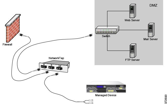
On the DMZ
The DMZ contains outward-facing servers (for example, web, FTP, DNS, and mail), and may also provide services such as mail relay and web proxy to users on the internal network.
Content stored in the DMZ is static, and changes are planned and executed with clear communication and advance notice. Attacks in this segment are typically inbound and become immediately apparent because only planned changes should occur on the servers in the DMZ. An effective access control policy for this segment tightly controls access to services and searches for any new network events.
Servers in the DMZ can contain a database that the DMZ can query via the network. Like the DMZ, there should be no unexpected changes, but the database content is more sensitive and requires greater protection than a web site or other DMZ service. A strong intrusion policy, in addition to the DMZ access control policy, is an effective strategy.
A managed device deployed on this segment can detect attacks directed to the Internet that originate from a compromised server in the DMZ. Monitoring network traffic using Network Discovery can help you monitor these exposed servers for changes (for example, an unexpected service suddenly appearing) that could indicate a compromised server in the DMZ.

On the Internal Network
A malicious attack can originate from a computer on your internal network. This can be a deliberate act (for example, an unknown computer appears unexpectedly on your network), or an accidental infection (for example, a work laptop infected off-site is connected to the network and spreads a virus). Risk on the internal network can also be outbound (for example, a computer sends information to a suspicious external IP address).
This dynamic network requires a strict access control policy for all internal traffic in addition to outbound traffic. Add access control rules to tightly control traffic between users and applications.

On the Core Network
Core assets are those assets critical to the success of your business that must be protected at all cost. Although core assets vary depending on the nature of your business, typical core assets include financial and management centers or intellectual property repositories. If the security on the core assets is breached, your business can be destroyed.
Although this segment must be readily available for your business to function, it must be tightly restricted controlled. Access control should ensure that these assets cannot be reached by those network segments with the highest risk, such as remote networks or mobile devices. Always use the most aggressive control on this segment, with strict rules for user and application access.

On a Remote or Mobile Network
Remote networks, located off-site, often use a virtual private network (VPN) to provide access to the primary network. Mobile devices and the use of personal devices for business purposes (for example, using a “smart phone” to access corporate email) are becoming increasingly common.
These networks can be highly dynamic environments with rapid and continual change. Deploying a managed device on a dedicated mobile or remote network allows you to create a strict access control policy to monitor and manage traffic to and from unknown external sources. Your policy can reduce your risk by rigidly limiting how users, network, and applications access core resources.

Using Multiple Sensing Interfaces on a Managed Device
The managed device offers multiple sensing interfaces on its network modules. You can use multiple sensing interfaces on managed devices to:
- recombine the separate connections from a network tap
- capture and evaluate traffic from different networks
- perform as a virtual router
- perform as a virtual switch
Note![]() Although each sensing interface is capable of receiving the full throughput for which the device is rated, the total traffic on the managed device cannot exceed its bandwidth rating without some packet loss.
Although each sensing interface is capable of receiving the full throughput for which the device is rated, the total traffic on the managed device cannot exceed its bandwidth rating without some packet loss.
Deploying multiple sensing interfaces on a managed device with a network tap is a straightforward process. The following diagram shows a network tap installed on a high-traffic network segment.

In this scenario, the tap transmits incoming and outgoing traffic through separate sensing interfaces. When you connect the multiple sensing interface adapter card on the managed device to the tap, the managed device is able to combine the traffic into a single data stream so that it can be analyzed.
Note that with a gigabit optical tap, as shown in the illustration below, both sets of sensing interfaces on the managed device are used by the connectors from the tap.
You can use the virtual switch to replace both the tap and the switch in your deployment. Note that if you replace the tap with a virtual switch, you lose the tap packet delivery guarantee.

You can also create interfaces to capture data from separate networks. The following diagram shows a single device with a dual sensing interface adapter and two interfaces connected to two networks.

In addition to using one device to monitor both network segments, you can use the virtual switch capability of the device to replace both switches in your deployment.

Complex Network Deployments
Your enterprise’s network may require remote access, such as using a VPN, or have multiple entry points, such as a business partner or banking connection. The following sections describe some of the issues involved with these deployments:
- Integrating with VPNs
- Detecting Intrusions on Other Points of Entry
- Deploying in Multi-Site Environments
- Integrating Multiple Management Interfaces within a Complex Network
- Integrating Managed Devices within Complex Networks
Integrating with VPNs
Virtual private networks, or VPNs, use IP tunneling techniques to provide the security of a local network to remote users over the Internet. In general, VPN solutions encrypt the data payload in an IP packet. The IP header is unencrypted so that the packet can be transmitted over public networks in much the same way as any other packet. When the packet arrives at its destination network, the payload is decrypted and the packet is directed to the proper host.
Because network appliances cannot analyze the encrypted payload of a VPN packet, placing managed devices outside the terminating endpoints of the VPN connections ensures that all packet information can be accessed. The following diagram illustrates how managed devices can be deployed in a VPN environment.

You can replace the firewall and the tap on either side of the VPN connection with the managed device. Note that if you replace the tap with a managed device, you lose the tap packet delivery guarantee.

Detecting Intrusions on Other Points of Entry
Many networks include more than one access point. Instead of a single border router that connects to the Internet, some enterprises use a combination of the Internet, modem banks, and direct links to business partner networks. In general, you should deploy managed devices near firewalls (either inside the firewall, outside the firewall, or both) and on network segments that are important to the integrity and confidentiality of your business data. The following diagram shows how managed devices can be installed at key locations on a complex network with multiple entry points.

You can replace the firewall and the router with the managed device deployed on that network segment.

Deploying in Multi-Site Environments
Many organizations want to extend intrusion detection across a geographically disparate enterprise and then analyze all the data from one location. The FireSIGHT System supports this by offering the Defense Center, which aggregates and correlates events from managed devices deployed throughout the organization’s many locations. Unlike deploying multiple managed devices and Defense Centers in the same geographic location on the same network, when deploying managed devices in disparate geographic locations, you must take precautions to ensure the security of the managed devices and the data stream. To secure the data, you must isolate the managed devices and Defense Center from unprotected networks. You can do this by transmitting the data stream from the managed devices over a VPN or with some other secure tunneling protocol as shown in the following diagram.

You can replace the firewalls and routers with the managed device deployed in each network segment.

Integrating Multiple Management Interfaces within a Complex Network
You can configure multiple management interfaces in any deployment to isolate traffic from devices that monitor different networks and are managed by the same Defense Center. Multiple management interfaces allow you to add a management interface with a unique IP address (IPv4 or IPv6) to your Defense Center, and create a route from that management interface to a network that contains the device you want to manage. When you register your device to the new management interface, traffic on that device is isolated from traffic on devices registered to the default management interface on the Defense Center.

Tip You must register a device to the static IP address of any management interface other than the default (eth0) management interface. DHCP is supported only on the default management interface.
Multiple management interfaces are supported in a NAT environment provided you do not use separate management interfaces for traffic channels. See Deploying on a Management Network for more information. Note that Lights-Out Management is supported only on the default management interface, not additional management interfaces.
After you install your Defense Center, you configure multiple management interfaces using the web interface. See Configuring Appliance Settings in the FireSIGHT System User Guide for more information.
Integrating Managed Devices within Complex Networks
You can deploy managed devices in more complex network topologies than a simple multi-sector network. This section describes the issues surrounding network discovery and vulnerability analysis when deploying in environments where proxy servers, NAT devices, and VPNs exist, in addition to information about using the FireSIGHT Defense Center to manage multiple managed devices and the deployment and management of managed devices in a multi-site environment.
Integrating with Proxy Servers and NAT
Network address translation (NAT) devices or software may be employed across a firewall, effectively hiding the IP addresses of internal hosts behind a firewall. If managed devices are placed between these devices or software and the hosts being monitored, the system may incorrectly identify the hosts behind the proxy or NAT device. In this case, Cisco recommends that you position managed devices inside the network segment protected by the proxy or NAT device to ensure that hosts are correctly detected.
Integrating with Load Balancing Methods
In some network environments, “server farm” configurations are used to perform network load balancing for services such as web hosting, FTP storage sites, and so on. In load balancing environments, IP addresses are shared between two or more hosts with unique operating systems. In this case, the system detects the operating system changes and cannot deliver a static operating system identification with a high confidence value. Depending on the number of different operating systems on the affected hosts, the system may generate a large number of operating system change events or present a static operating system identification with a lower confidence value.
Other Detection Considerations
If an alteration has been made to the TCP/IP stack of the host being identified, the system may not be able to accurately identify the host operating system. In some cases, this is done to improve performance. For instance, administrators of Windows hosts running the Internet Information Services (IIS) Web Server are encouraged to increase the TCP window size to allow larger amounts of data to be received, thereby improving performance. In other instances, TCP/IP stack alteration may be used to obfuscate the true operating system to preclude accurate identification and avoid targeted attacks. The likely scenario that this intends to address is where an attacker conducts a reconnaissance scan of a network to identify hosts with a given operating system followed by a targeted attack of those hosts with an exploit specific to that operating system.
 Feedback