Cable and Onboard the Firewall

Cable and onboard the firewall to CDO.

Cable the Firewall

Cabling for CDO

Onboard the Firewall to CDO

Onboard the firewall using zero-touch provisioning or manual provisioning.

Onboard the Firewall with Zero-Touch Provisioning

Onboard the threat defense using zero-touch provisioning and the device serial number.

Procedure


Step 1

In the CDO navigation pane, click Inventory, then click the blue plus button (plus sign) to Onboard a device.

Step 2

Select the FTD tile.

Step 3

Under Management Mode, be sure FTD is selected.

At any point after selecting FTD as the management mode, you can click Manage Smart License to enroll in or modify the existing smart licenses available for your device. See Obtain Licenses to see which licenses are available.

Step 4

Select Use Serial Number as the onboarding method.

Figure 1. Use Serial Number
Use Serial Number

Step 5

In Select FMC, choose the Cloud-Delivered FMC > Firewall Management Center from the list, and click Next.

Figure 2. Select FMC
Select FMC

Step 6

In the Connection area, enter the Device Serial Number and the Device Name and then click Next.

Figure 3. Connection
Connection

Step 7

In Password Reset, click Yes.... Enter a new password and confirm the new password for the device, then click Next.

For zero-touch provisioning, the device must be brand new or has been reimaged.

Note


If you logged into the device and reset the password, and you did not change the configuration in a way that would disable zero-touch provisioning, then you should choose the No... option. There are a number of configurations that disable zero-touch provisioning provisioning, so we don't recommend logging into the device unless you need to, for example, to perform a reimage.

Figure 4. Password Reset
Password Reset

Step 8

For the Policy Assignment, use the drop-down menu to choose an access control policy for the device. If you have no policies configured, choose the Default Access Control Policy.

Figure 5. Policy Assignment
Policy Assignment

Step 9

For the Subscription License, check each of the feature licenses you want to enable. Click Next.

Figure 6. Subscription License
Subscription License

Step 10

(Optional) Add labels to your device to help sort and filter the Inventory page. Enter a label and select the blue plus button (plus sign). Labels are applied to the device after it's onboarded to CDO.

Figure 7. Done
Done

What to do next

From the Inventory page, select the device you just onboarded and select any of the option listed under the Management pane located to the right.

Onboard the Firewall with Manual Provisioning

Onboard the firewall using a CLI registration key.

Procedure


Step 1

In the CDO navigation pane, click Inventory, then click the blue plus button (plus sign) to Onboard a device.

Step 2

Click the FTD tile.

Step 3

Under Management Mode, be sure FTD is selected.

Step 4

Select Use CLI Registration Key as the onboarding method.

Figure 8. Use CLI Registration Key
Use CLI Registration Key

Step 5

Enter the Device Name and click Next.

Figure 9. Device Name
Device Name

Step 6

For the Policy Assignment, use the drop-down menu to choose an access control policy for the device. If you have no policies configured, choose the Default Access Control Policy.

Figure 10. Access Control Policy
Access Control Policy

Step 7

For the Subscription License, click the Physical FTD Device radio button, and then check each of the feature licenses you want to enable. Click Next.

Figure 11. Subscription License
Subscription License

Step 8

For the CLI Registration Key, CDO generates a command with the registration key and other parameters. You must copy this command and use it in the intial configuration of the threat defense.

Figure 12. CLI Registration Key
CLI Registration Key

configure manager add cdo_hostname registration_key nat_id display_name

Complete initial configuration at the CLI or using the device manager:

  • Initial Configuration: CLI—Copy this command at the threat defense CLI after you complete the startup script.

  • Initial Configuration: Device Manager—Copy the cdo_hostname , registration_key , and nat_id parts of the command into the Management Center/CDO Hostname/IP Address, Management Center/CDO Registration Key, and NAT ID fields.

Example:

Sample command for CLI setup:


configure manager add account1.app.us.cdo.cisco.com KPOOP0rgWzaHrnj1V5ha2q5Rf8pKFX9E
Lzm1HOynhVUWhXYWz2swmkj2ZWsN3Lb account1.app.us.cdo.cisco.com

Sample command components for GUI setup:

Figure 13. configure manager add command components
configure manager add command components

Step 9

Click Next in the onboarding wizard to start registering the device.

Step 10

(Optional) Add labels to your device to help sort and filter the Inventory page. Enter a label and select the blue plus button (plus sign). Labels are applied to the device after it's onboarded to CDO.

Figure 14. Done
Done

Perform Initial Configuration (Manual Provisioning)

For manual provisioning, perfom initial configuration of the firewall using the Secure Firewall device manager or using the CLI.

Initial Configuration: Device Manager

Using this method, after you register the firewall, the following interfaces will be preconfigured in addition to the Management interface:

  • Ethernet 1/1—outside, IP address from DHCP, IPv6 autoconfiguration

  • VLAN1inside, 192.168.95.1/24

  • Default route—Obtained through DHCP on the outside interface

  • Additional interfaces—Any interface configuration from the device manager is preserved.

Other settings, such as the DHCP server on inside, access control policy, or security zones, are not preserved.

Procedure


Step 1

Connect your computer to the inside interface (Ethernet 1/2 through 1/8 or for the Secure Firewall 1220, 1/2 through 1/10).

Step 2

Log into the device manager.

  1. Go to https://192.168.95.1.

  2. Log in with the username admin and the default password Admin123.

  3. You are prompted to read and accept the General Terms and change the admin password.

Step 3

Use the setup wizard.

Figure 15. Device Setup
Device Setup

Note


The exact port configuration depends on your model.

  1. Configure the outside and management interfaces.

    Figure 16. Connect firewall to internet
    Connect firewall to internet
    1. Outside Interface Address—Use a static IP address if you plan for high availability. You cannot configure PPPoE using the setup wizard; you can configure PPPoE after you complete the wizard.

    2. Management Interface—The Management interface settings are used even though you are using manager access on the outside interface. For example, management traffic that is routed over the backplane through the outside interface will resolve FQDNs using these Management interface DNS servers, and not the outside interface DNS servers.

      DNS Servers—The DNS server for the system's management address. The default is the OpenDNS public DNS servers. These will probably match the outside interface DNS servers you set later since they are both accessed from the outside interface.

      Firewall Hostname

  2. Configure the Time Setting (NTP) and click Next.

    Figure 17. Time Setting (NTP)
    Connect firewall to internet
  3. Select Start 90 day evaluation period without registration.

    Connect firewall to internet

    Do not register the threat defense with the Smart Software Manager; all licensing is performed on the CDO.

  4. Click Finish.

    Figure 18. What's Next
    Connect firewall to internet
  5. Choose Standalone Device, and then Got It.

Step 4

If you want to configure additional interfaces, choose Device, and then click the link in the Interfaces summary.

Step 5

Register with the CDO by choosing Device > System Settings > Central Management and clicking Proceed

Configure the Management Center/CDO Details.

Figure 19. Management Center/CDO Details
Management Center/CDO Details
  1. For Do you know the Management Center/CDO hostname or IP address, click Yes.

    CDO generates the configure manager add command. See Onboard the Firewall with Manual Provisioning to generate the command.

    configure manager add cdo_hostname registration_key nat_id display_name

    Example:

    Figure 20. configure manager add command components
    configure manager add command components
  2. Copy the cdo_hostname , registration_key , and nat_id parts of the command into the Management Center/CDO Hostname/IP Address, Management Center/CDO Registration Key, and NAT ID fields.

Step 6

Configure the Connectivity Configuration.

  1. Specify the Threat Defense Hostname.

    This FQDN will be used for the outside interface.

  2. Specify the DNS Server Group.

    Choose an existing group, or create a new one. The default DNS group is called CiscoUmbrellaDNSServerGroup, which includes the OpenDNS servers.

    To retain the outside DNS server setting after registration, you need to re-configure the DNS Platform Settings in the management center.

  3. For the Management Center/CDO Access Interface, click Data Interface, and then choose outside.

Step 7

(Optional) Click Add a Dynamic DNS (DDNS) method.

DDNS ensures the management center can reach the threat defense at its FQDN if the threat defense's IP address changes.

Step 8

Click Connect.

The Registration Status dialog box shows the current status of the CDO registration.

Figure 21. Successful Connection
Successful Connection

Step 9

After the Saving Management Center/CDO Registration Settings step on the status screen, go to the CDO and add the firewall. See Onboard the Firewall with Manual Provisioning.


Initial Configuration: CLI

Set the dedicated Management IP address, gateway, and other basic networking settings using the CLI setup script.

Procedure


Step 1

Connect to the console port and access the threat defense CLI. See Access the Threat Defense CLI.

Step 2

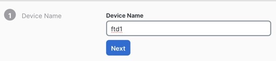
Complete the CLI setup script for the Management interface settings.

Note


You cannot repeat the CLI setup script unless you clear the configuration, for example, by reimaging. However, all of these settings can be changed later at the CLI using configure network commands. See Cisco Secure Firewall Threat Defense Command Reference.


You must accept the EULA to continue.
Press <ENTER> to display the EULA:                 
Cisco General Terms
[...]

Please enter 'YES' or press <ENTER> to AGREE to the EULA:

System initialization in progress.  Please stand by.
You must configure the network to continue.
Configure at least one of IPv4 or IPv6 unless managing via data interfaces.
Do you want to configure IPv4? (y/n) [y]:
Do you want to configure IPv6? (y/n) [y]: n

Guidance: Enter y for at least one of these types of addresses. Although you 
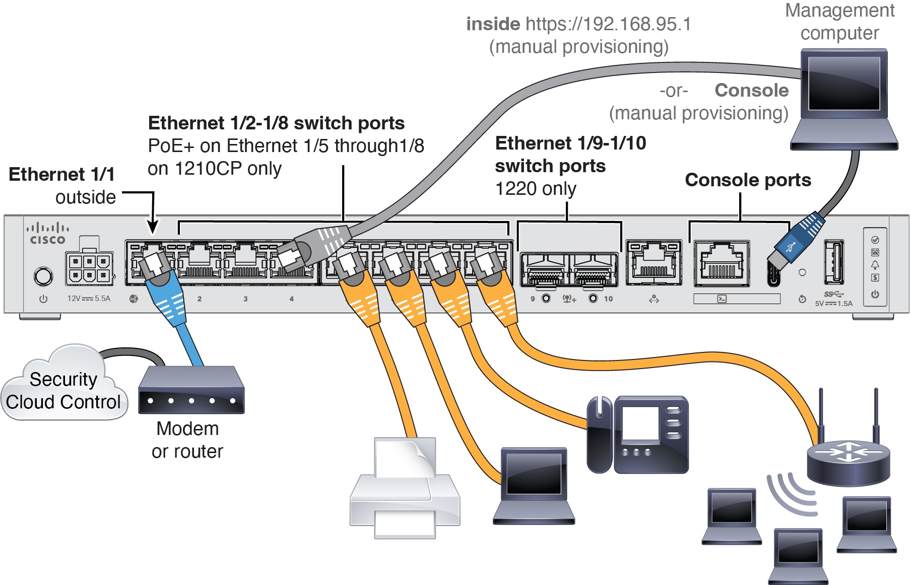
do not plan to use the Management interface, you must set an IP address, for example, a private address.

Configure IPv4 via DHCP or manually? (dhcp/manual) [manual]:

Guidance: Choose manual. DHCP is not supported when using the outside interface for manager access. Make sure this interface is on a different subnet from the manager access interface to prevent routing issues.

Enter an IPv4 address for the management interface [192.168.45.61]: 10.89.5.17
Enter an IPv4 netmask for the management interface [255.255.255.0]: 255.255.255.192
Enter the IPv4 default gateway for the management interface [data-interfaces]:

Guidance: Set the gateway to be data-interfaces. This setting forwards management traffic over the backplane so it can be routed through the outside interface.

Enter a fully qualified hostname for this system [firepower]: 1010-3
Enter a comma-separated list of DNS servers or 'none' [208.67.222.222,208.67.220.220,2620:119:35::35]:
Enter a comma-separated list of search domains or 'none' []: cisco.com
If your networking information has changed, you will need to reconnect.
Disabling IPv6 configuration: management0
Setting DNS servers: 208.67.222.222,208.67.220.220,2620:119:35::35
Setting DNS domains:cisco.com

Guidance: Set the Management interface DNS servers. These will probably match the outside interface DNS servers you set later, since they are both accessed from the outside interface.

Setting hostname as 1010-3
Setting static IPv4: 10.89.5.17 netmask: 255.255.255.192 gateway: data on management0
Updating routing tables, please wait...
All configurations applied to the system. Took 3 Seconds.
Saving a copy of running network configuration to local disk.
For HTTP Proxy configuration, run 'configure network http-proxy'

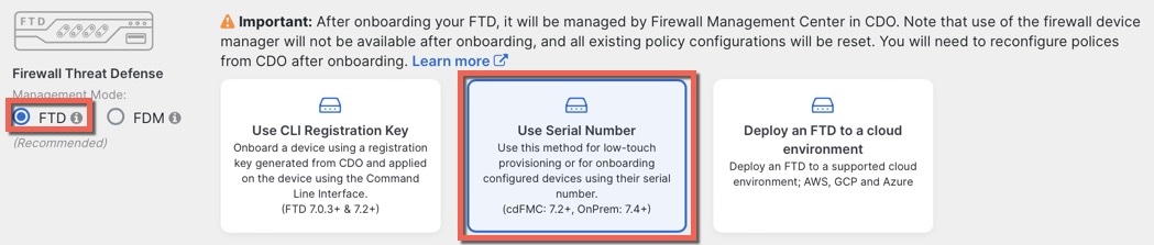
Manage the device locally? (yes/no) [yes]: no

Guidance: Enter no to use the management center.

Setting hostname as 1010-3
Setting static IPv4: 10.89.5.17 netmask: 255.255.255.192 gateway: data on management0
Updating routing tables, please wait...
All configurations applied to the system. Took 3 Seconds.
Saving a copy of running network configuration to local disk.
For HTTP Proxy configuration, run 'configure network http-proxy'

Guidance: Enter routed. Outside manager access is only supported in routed firewall mode.

Configuring firewall mode ...


Device is in OffBox mode - disabling/removing port 443 from iptables.
Update policy deployment information
    - add device configuration
    - add network discovery
    - add system policy

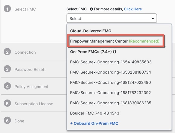
You can register the sensor to a Firepower Management Center and use the
Firepower Management Center to manage it. Note that registering the sensor
to a Firepower Management Center disables on-sensor Firepower Services
management capabilities.

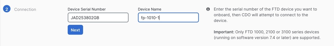
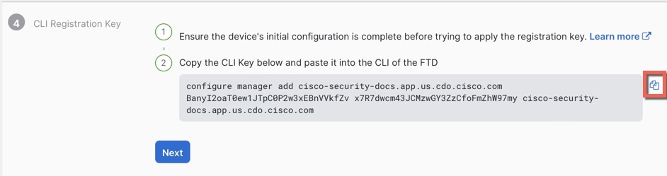
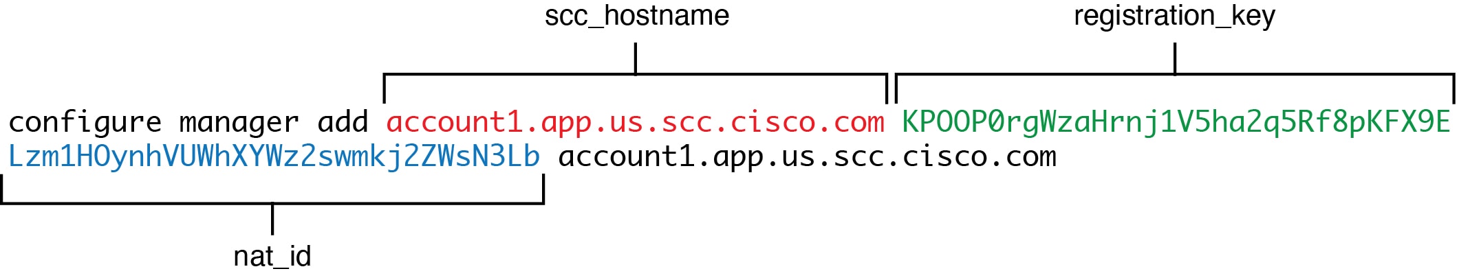
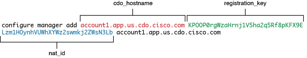
When registering the sensor to a Firepower Management Center, a unique
alphanumeric registration key is always required.  In most cases, to register
a sensor to a Firepower Management Center, you must provide the hostname or
the IP address along with the registration key.
'configure manager add [hostname | ip address ] [registration key ]'

However, if the sensor and the Firepower Management Center are separated by a
NAT device, you must enter a unique NAT ID, along with the unique registration
key.
'configure manager add DONTRESOLVE [registration key ] [ NAT ID ]'

Later, using the web interface on the Firepower Management Center, you must
use the same registration key and, if necessary, the same NAT ID when you add
this sensor to the Firepower Management Center.
>

Step 3

Configure the outside interface for manager access.

configure network management-data-interface

You are then prompted to configure basic network settings for the outside interface.

Manual IP Address


> configure network management-data-interface
Data interface to use for management: ethernet1/1
Specify a name for the interface [outside]: internet
IP address (manual / dhcp) [dhcp]: manual
IPv4/IPv6 address: 10.10.6.7
Netmask/IPv6 Prefix: 255.255.255.0
Default Gateway: 10.10.6.1
Comma-separated list of DNS servers [none]: 208.67.222.222,208.67.220.220

Guidance: To retain the outside DNS servers after registration, you need to re-configure the DNS Platform Settings in the management center.


DDNS server update URL [none]:
Do you wish to clear all the device configuration before applying ? (y/n) [n]:

Configuration done with option to allow manager access from any network, if you wish to change the manager access network
use the 'client' option in the command 'configure network management-data-interface'.

Setting IPv4 network configuration.
Network settings changed.

>

IP Address from DHCP


> configure network management-data-interface
Data interface to use for management: ethernet1/1
Specify a name for the interface [outside]:
IP address (manual / dhcp) [dhcp]:  
DDNS server update URL [none]: https://dwinchester:pa$$w0rd17@domains.example.com/nic/update?hostname=<h>&myip=<a>
Do you wish to clear all the device configuration before applying ? (y/n) [n]:

Configuration done with option to allow manager access from any network, if you wish to change the manager access network 
use the 'client' option in the command 'configure network management-data-interface'.

Setting IPv4 network configuration.
Network settings changed.

> 

Step 4

Identify the CDO that will manage this threat defense using the configure manager add command that CDO generated. See Onboard the Firewall with Manual Provisioning to generate the command.

Example:


> configure manager add account1.app.us.cdo.cisco.com KPOOP0rgWzaHrnj1V5ha2q5Rf8pKFX9E
Lzm1HOynhVUWhXYWz2swmkj2ZWsN3Lb account1.app.us.cdo.cisco.com
Manager successfully configured.

Step 5

Shut down the threat defense so you can send the device to the remote branch office.

It's important that you shut down your system properly. Simply unplugging the power or pressing the power switch can cause serious file system damage. Remember that there are many processes running in the background all the time, and unplugging or shutting off the power does not allow the graceful shutdown of your system.

  1. Enter the shutdown command.

  2. Observe the Power LED and Status LED to verify that the chassis is powered off (appear unlit).

  3. After the chassis has successfully powered off, you can then unplug the power to physically remove power from the chassis if necessary.