Configure Interfaces
When you use zero-touch provisioning or the device manager for initial setup instead of using the CLI, the following interfaces are preconfigured:
-
Ethernet 1/1—outside, IP address from DHCP, IPv6 autoconfiguration
-
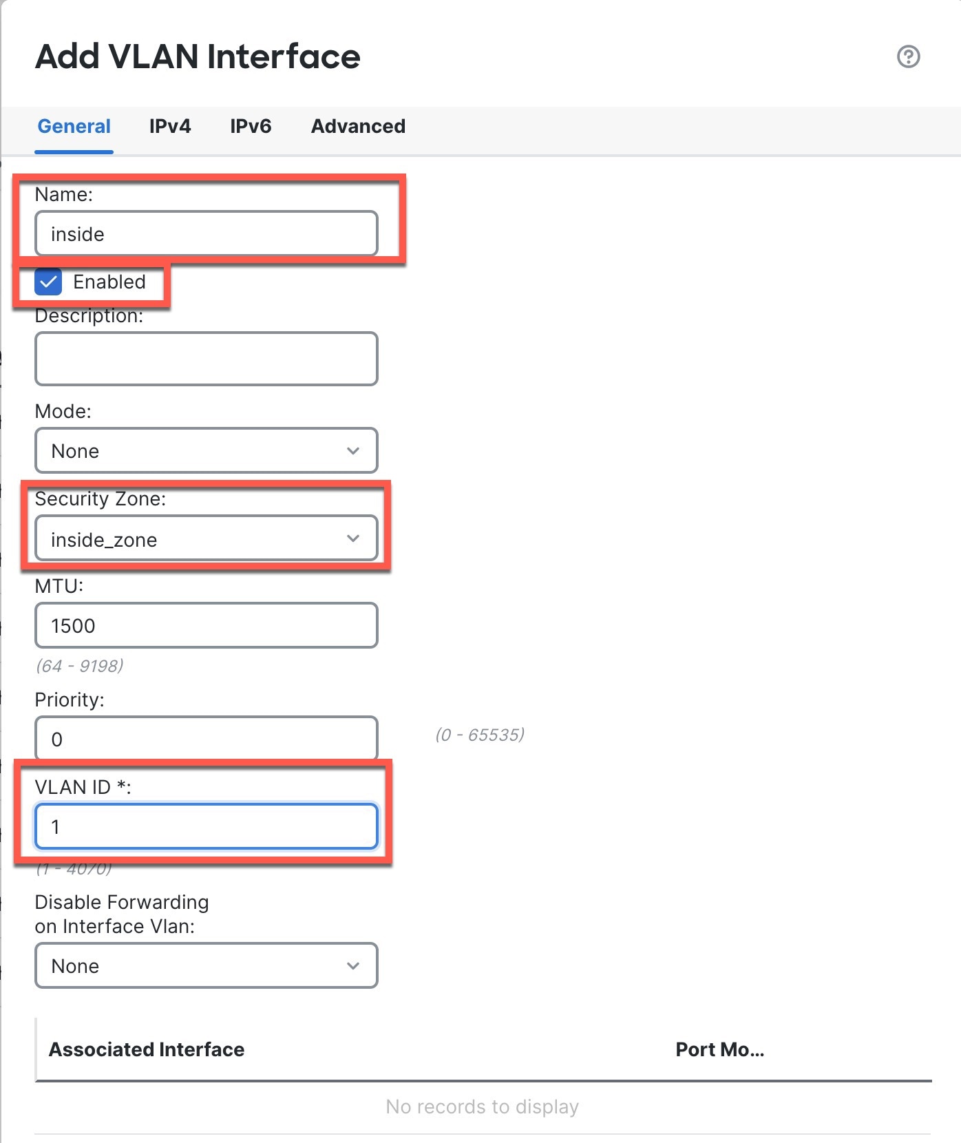
VLAN1— inside, 192.168.95.1/24
-
Default route—Obtained through DHCP on the outside interface
If you performed additional interface-specific configuration within device manager before registering with the management center, then that configuration is preserved.
If you used the CLI for initial setup, there is no preconfiguration of your device.
In both cases, you need to perform additional interface configuration after you register the device. For CLI initial setup, you must add the VLAN1 interface for the inside switch ports. Additional configuration includes converting switch ports to firewall interfaces as desired, assigning interfaces to security zones, and changing IP addresses.
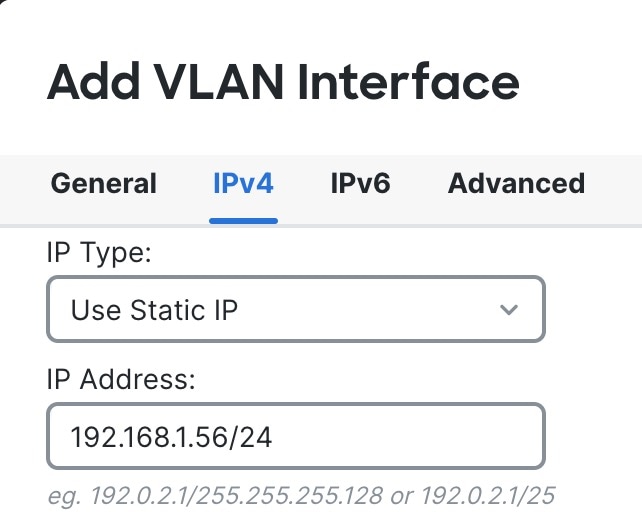
The following example configures a routed-mode inside interface (VLAN1) with a static address and a routed-mode outside interface using DHCP (Ethernet1/1). It also adds a DMZ interface for an internal web server.
Procedure
|
Step 1 |
Choose , and click Edit ( |
|
Step 2 |
Click Interfaces. 
|
|
Step 3 |
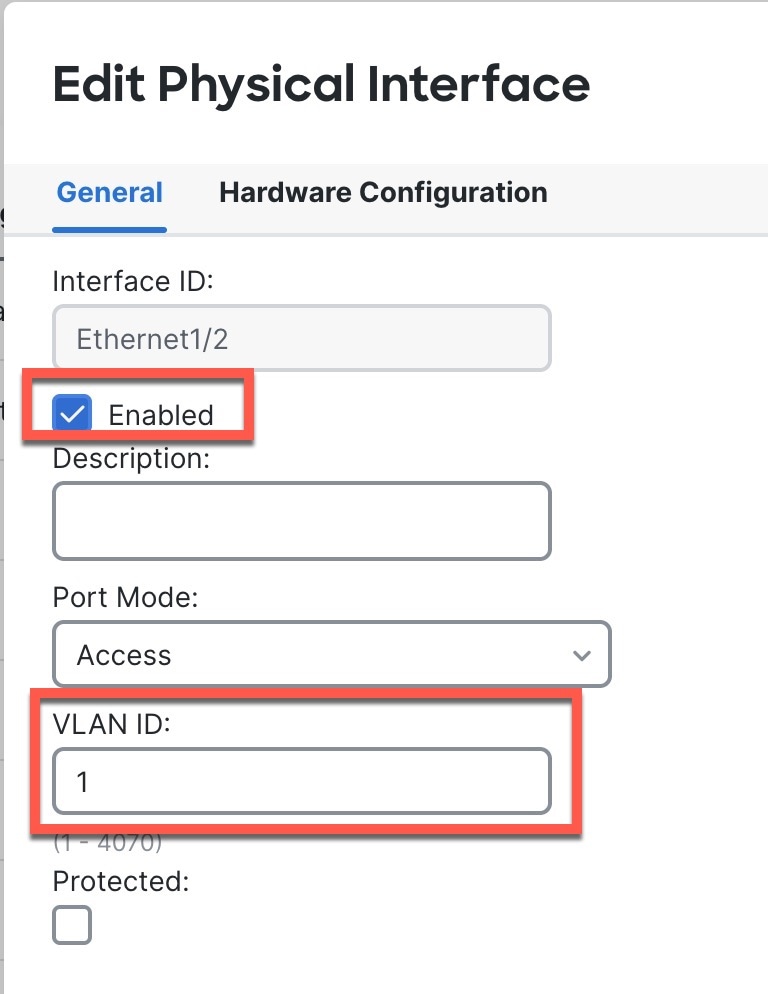
If you used the CLI for initial setup, enable the switch ports.
|
|
Step 4 |
Add (or edit) the inside VLAN interface.
|
|
Step 5 |
Click Edit ( The General page appears. 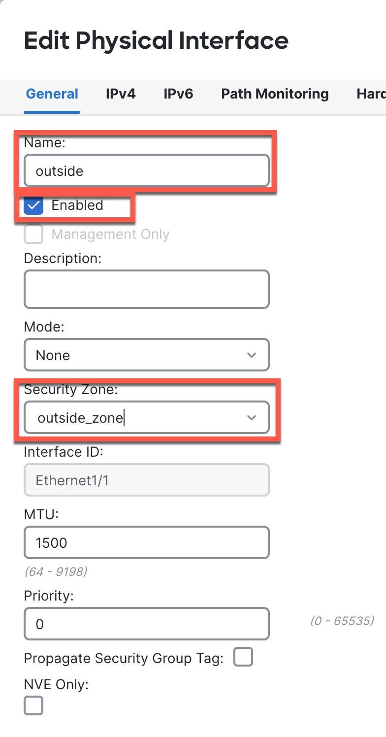
|
|
Step 6 |
Configure a DMZ interface to host a web server, for example.
|
|
Step 7 |
Click Save. |


 Feedback