Configure Interfaces
When you use zero-touch provisioning or the device manager for initial setup, the following interfaces are preconfigured:
-
Ethernet 1/1—outside, IP address from DHCP, IPv6 autoconfiguration
-
Ethernet 1/2— inside, 192.168.95.1/24
-
Default route—Obtained through DHCP on the outside interface
If you performed additional interface-specific configuration within device manager before registering with the management center, then that configuration is preserved.
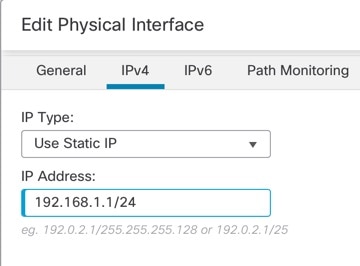
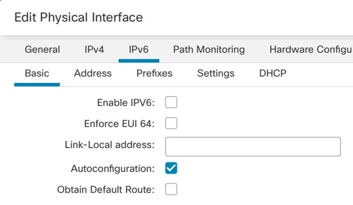
The following example configures a routed-mode inside interface with a static address and a routed-mode outside interface using DHCP. It also adds a DMZ interface for an internal web server.
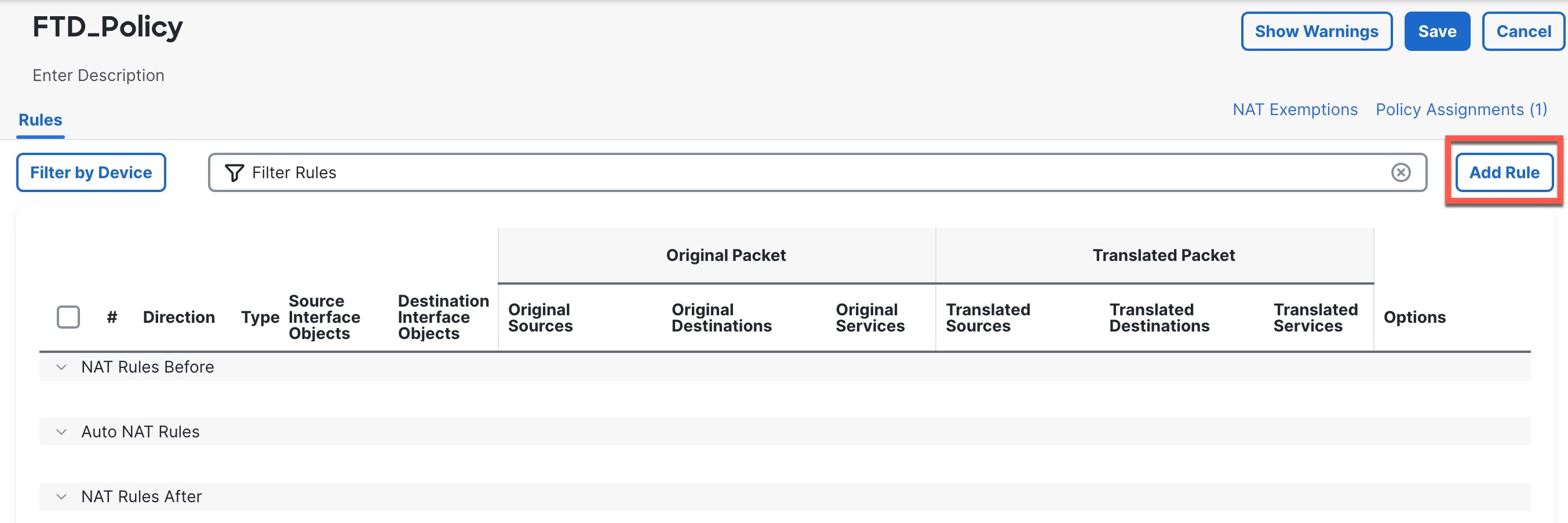
Procedure
|
Step 1 |
Choose , and click Edit ( |
|
Step 2 |
Click Interfaces. 
|
|
Step 3 |
To create breakout ports from a 40-Gb or larger interface, click the Break icon for the interface. If you already used the full interface in your configuration, you will have to remove the configuration before you can proceed with the breakout. |
|
Step 4 |
Click Edit ( 
|
|
Step 5 |
Click Edit ( 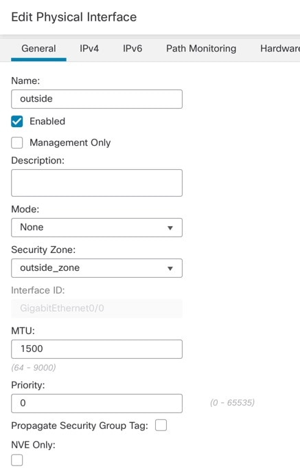
|
|
Step 6 |
Configure a DMZ interface to host a web server, for example.
|
|
Step 7 |
Click Save. |


 Feedback