- Preface
-
- Getting Started with Security Manager
- Preparing Devices for Management
- Managing the Device Inventory
- Managing Activities
- Managing Policies
- Managing Policy Objects
- Managing FlexConfigs
- Managing Deployment
- Troubleshooting Device Communication and Deployment
- Managing the Security Manager Server
- Configuring Security Manager Administrative Settings
-
- Introduction to Firewall Services
- Managing Identity-Aware Firewall Policies
- Managing TrustSec Firewall Policies
- Managing Firewall AAA Rules
- Managing Firewall Access Rules
- Managing Firewall Inspection Rules
- Managing Firewall Web Filter Rules
- Managing Firewall Botnet Traffic Filter Rules
- Working with ScanSafe Web Security
- Managing Zone-based Firewall Rules
- Managing Traffic Zones
- Managing Transparent Firewall Rules
- Configuring Network Address Translation
-
- Managing Site-to-Site VPNs: The Basics
- Configuring IKE and IPsec Policies
- GRE and DM VPNs
- Easy VPN
- Group Encrypted Transport (GET) VPNs
- Managing Remote Access VPNs: The Basics
- Managing Remote Access VPNs on ASA and PIX 7.0+ Devices
- Managing Dynamic Access Policies for Remote Access VPNs (ASA 8.0+ Devices)
- Managing Remote Access VPNs on IOS and PIX 6.3 Devices
- Configuring Policy Objects for Remote Access VPNs
- Using Map View
-
- Getting Started with IPS Configuration
- Managing IPS Device Interfaces
- Configuring Virtual Sensors
- Defining IPS Signatures
- Configuring Event Action Rules
- Managing IPS Anomaly Detection
- Configuring Global Correlation
- Configuring Attack Response Controller for Blocking and Rate Limiting
- Managing IPS Sensors
- Configuring IOS IPS Routers
-
- Managing Firewall Devices
- Configuring Bridging Policies on Firewall Devices
- Configuring Device Administration Policies on Firewall Devices
- Configuring Device Access Settings on Firewall Devices
- Configuring Failover
- Configuring Hostname, Resources, User Accounts, and SLAs
- Configuring Server Access Settings on Firewall Devices
- Configuring FXOS Server Access Settings on Firepower 2100 Series Devices
- Configuring Logging Policies on Firewall Devices
- Configuring Multicast Policies on Firewall Devices
- Configuring Routing Policies on Firewall Devices
- Configuring Security Policies on Firewall Devices
- Configuring Service Policy Rules on Firewall Devices
- Configuring Security Contexts on Firewall Devices
- User Preferences
- Index
Configuring Routing Policies on Firewall Devices
The Routing section in Security Manager contains pages for defining and managing routing settings for security appliances.
Configuring No Proxy ARP
When a host sends IP traffic to another device on the same Ethernet network, the host needs to know the MAC address of the device. Address Resolution Protocol (ARP) is a Layer 2 protocol that resolves an IP address to a MAC address: a host sends an ARP request asking “Who is this IP address?” The device owning the IP address replies, “I own that IP address; here is my MAC address.”
With Proxy ARP, a device responds to an ARP request with its own MAC address, even though the device does not own the IP address. Serving as an ARP Proxy for another host effectively directs network traffic to the proxy, in this case your security appliance. Traffic that passes through the appliance is then routed to the appropriate destination.
For example, the security appliance uses proxy ARP when you configure NAT and specify a global address that is on the same network as the appliance interface. The only way traffic can reach the destination hosts is if the appliance claims and subsequently routes traffic to the destination global addresses.
By default, proxy ARP is enabled for all interfaces. Use the No Proxy ARP page to disable proxy ARP for global addresses:
- To disable proxy ARP for one or more interfaces, enter their names in the Interfaces field. Separate multiple interfaces with commas. You can click Select to choose the interfaces from a list of interfaces defined on the device, and interface roles defined in Security Manager.

Note![]() On ASA 8.4.2 and later devices operating in routed mode, you can disable Proxy ARP on the egress interface for a Manual NAT rule. See Do not proxy ARP on Destination Interface for more information.
On ASA 8.4.2 and later devices operating in routed mode, you can disable Proxy ARP on the egress interface for a Manual NAT rule. See Do not proxy ARP on Destination Interface for more information.
Configuring BGP
Border Gateway Protocol (BGP) is an inter autonomous system routing protocol. An autonomous system is a network or group of networks under a common administration and with common routing policies. BGP is used to exchange routing information for the Internet and is the protocol used between Internet service providers (ISP).
Note![]() BGP configuration is supported on ASA 9.2(1)+ only. Also, beginning with ASA 9.3(1), BGP is supported in L2 (EtherChannel Type) and L3 (Individual Interface Type) clustering modes.
BGP configuration is supported on ASA 9.2(1)+ only. Also, beginning with ASA 9.3(1), BGP is supported in L2 (EtherChannel Type) and L3 (Individual Interface Type) clustering modes.
- (Device view) Select Platform > Routing > BGP from the Device Policy selector.
- (Policy view) Select PIX/ASA/FWSM Platform > Routing > BGP from the Policy Type selector. Select an existing policy from the Shared Policy selector, or create a new one.
The BGP page provides two tabbed panels for configuring BGP routing on a firewall device. This is the basic procedure for configuring the BGP process:
1.![]() Enable the BGP routing process by checking the Enable BGP check box on the BGP page.
Enable the BGP routing process by checking the Enable BGP check box on the BGP page.
2.![]() In the AS Number field, enter the autonomous system (AS) number for the BGP process. The AS number internally includes multiple autonomous numbers. The AS number can be from 1 to 4294967295 or from 1.0 to 65535.65535.
In the AS Number field, enter the autonomous system (AS) number for the BGP process. The AS number internally includes multiple autonomous numbers. The AS number can be from 1 to 4294967295 or from 1.0 to 65535.65535.
3.![]() On the General Tab:
On the General Tab:
–![]() (Optional) Check the Limit the number of AS numbers in AS_PATH attribute of received routes check box to restrict the number of AS numbers in AS_PATH attribute to a specific number. Valid values are from 1 to 254.
(Optional) Check the Limit the number of AS numbers in AS_PATH attribute of received routes check box to restrict the number of AS numbers in AS_PATH attribute to a specific number. Valid values are from 1 to 254.
–![]() (Optional) Check the Log Neighbor Changes check box to enable logging of BGP neighbor changes (up or down) and resets. This helps in troubleshooting network connectivity problems and measuring network stability.
(Optional) Check the Log Neighbor Changes check box to enable logging of BGP neighbor changes (up or down) and resets. This helps in troubleshooting network connectivity problems and measuring network stability.
–![]() (Optional) Check the Use TCP path MTU Discovery check box to use the Path MTU Discovery technique to determine the maximum transmission unit (MTU) size on the network path between two IP hosts. This avoids IP fragmentation.
(Optional) Check the Use TCP path MTU Discovery check box to use the Path MTU Discovery technique to determine the maximum transmission unit (MTU) size on the network path between two IP hosts. This avoids IP fragmentation.
–![]() (Optional) Check the Enable fast external failover check box to reset the external BGP session immediately upon link failure.
(Optional) Check the Enable fast external failover check box to reset the external BGP session immediately upon link failure.
–![]() (Optional) Check the Enforce that the first AS is peer’s AS for EBGP routes check box to discard incoming updates received from external BGP peers that do not list their AS number as the first segment in the AS_PATH attribute. This prevents a mis-configured or unauthorized peer from misdirecting traffic by advertising a route as if it was sourced from another autonomous system.
(Optional) Check the Enforce that the first AS is peer’s AS for EBGP routes check box to discard incoming updates received from external BGP peers that do not list their AS number as the first segment in the AS_PATH attribute. This prevents a mis-configured or unauthorized peer from misdirecting traffic by advertising a route as if it was sourced from another autonomous system.
–![]() (Optional) Check the Use dot notation for AS numbers check box to split the full binary 4-byte AS number into two words of 16 bits each, separated by a dot. AS numbers from 0-65553 are represented as decimal numbers and AS numbers larger than 65535 are represented using the dot notation.
(Optional) Check the Use dot notation for AS numbers check box to split the full binary 4-byte AS number into two words of 16 bits each, separated by a dot. AS numbers from 0-65553 are represented as decimal numbers and AS numbers larger than 65535 are represented using the dot notation.
–![]() Define the configuration related to the best path selection process for BGP routing (see General Tab).
Define the configuration related to the best path selection process for BGP routing (see General Tab).
–![]() Specify the timer information in the Neighbor timers area (see General Tab).
Specify the timer information in the Neighbor timers area (see General Tab).
–![]() (Optional) Configure Graceful Restart (see General Tab).
(Optional) Configure Graceful Restart (see General Tab).
4.![]() On the IPv4 Family tab, select the Enable IPv4 Family check box and then use the tabs provided to configure IPv4 Address Family settings. For more information, see IPv4 Family Tab.
On the IPv4 Family tab, select the Enable IPv4 Family check box and then use the tabs provided to configure IPv4 Address Family settings. For more information, see IPv4 Family Tab.
5.![]() On the IPv6 Family tab, select the Enable IPv6 Family check box and then use the tabs provided to configure IPv6 Address Family settings. For more information, see IPv6 Family Tab
On the IPv6 Family tab, select the Enable IPv6 Family check box and then use the tabs provided to configure IPv6 Address Family settings. For more information, see IPv6 Family Tab
About BGP
BGP is an inter autonomous system routing protocol. An autonomous system is a network or group of networks under a common administration and with common routing policies. BGP is used to exchange routing information for the Internet and is the protocol used between Internet service providers (ISP).
Customer networks, such as universities and corporations, usually employ an Interior Gateway Protocol (IGP) such as OSPF for the exchange of routing information within their networks. Customers connect to ISPs, and ISPs use BGP to exchange customer and ISP routes. When BGP is used between autonomous systems (AS), the protocol is referred to as External BGP (EBGP). If a service provider is using BGP to exchange routes within an AS, then the protocol is referred to as Interior BGP (IBGP).
BGP neighbors exchange full routing information when the TCP connection between neighbors is first established. When changes to the routing table are detected, the BGP routers send to their neighbors only those routes that have changed. BGP routers do not send periodic routing updates, and BGP routing updates advertise only the optimal path to a destination network.
Routes learned via BGP have properties that are used to determine the best route to a destination, when multiple paths exist to a particular destination. These properties are referred to as BGP attributes and are used in the route selection process:
- Weight -- This is a Cisco-defined attribute that is local to a router. The weight attribute is not advertised to neighboring routers. If the router learns about more than one route to the same destination, the route with the highest weight is preferred.
- Local preference -- The local preference attribute is used to select an exit point from the local AS. Unlike the weight attribute, the local preference attribute is propagated throughout the local AS. If there are multiple exit points from the AS, the exit point with the highest local preference attribute is used as an exit point for a specific route.
- Multi-exit discriminator -- The multi-exit discriminator (MED) or metric attribute is used as a suggestion to an external AS regarding the preferred route into the AS that is advertising the metric. It is referred to as a suggestion because the external AS that is receiving the MEDs may also be using other BGP attributes for route selection. The route with the lower MED metric is preferred.
- Origin -- The origin attribute indicates how BGP learned about a particular route. The origin attribute can have one of three possible values and is used in route selection.
–![]() IGP- The route is interior to the originating AS. This value is set when the network router configuration command is used to inject the route into BGP.
IGP- The route is interior to the originating AS. This value is set when the network router configuration command is used to inject the route into BGP.
–![]() EGP-The route is learned via the Exterior Border Gateway Protocol (EBGP).
EGP-The route is learned via the Exterior Border Gateway Protocol (EBGP).
–![]() Incomplete- The origin of the route is unknown or learned in some other way. An origin of incomplete occurs when a route is redistributed into BGP.
Incomplete- The origin of the route is unknown or learned in some other way. An origin of incomplete occurs when a route is redistributed into BGP.
- AS_path -- When a route advertisement passes through an autonomous system, the AS number is added to an ordered list of AS numbers that the route advertisement has traversed. Only the route with the shortest AS_path list is installed in the IP routing table.
- Next hop -- The EBGP next-hop attribute is the IP address that is used to reach the advertising router. For EBGP peers, the next-hop address is the IP address of the connection between the peers. For IBGP, the EBGP next-hop address is carried into the local AS.
- Community -- The community attribute provides a way of grouping destinations, called communities, to which routing decisions (such as acceptance, preference, and redistribution) can be applied. Route maps are used to set the community attribute. The predefined community attributes are as follows:
–![]() no-export- Do not advertise this route to EBGP peers.
no-export- Do not advertise this route to EBGP peers.
–![]() no-advertise- Do not advertise this route to any peer.
no-advertise- Do not advertise this route to any peer.
–![]() internet- Advertise this route to the Internet community; all routers in the network belong to it.
internet- Advertise this route to the Internet community; all routers in the network belong to it.
BGP may receive multiple advertisements for the same route from different sources. BGP selects only one path as the best path. When this path is selected, BGP puts the selected path in the IP routing table and propagates the path to its neighbors. BGP uses the following criteria, in the order presented, to select a path for a destination:
- If the path specifies a next hop that is inaccessible, drop the update.
- Prefer the path with the largest weight.
- If the weights are the same, prefer the path with the largest local preference.
- If the local preferences are the same, prefer the path that was originated by BGP running on this router.
- If no route was originated, prefer the route that has the shortest AS_path.
- If all paths have the same AS_path length, prefer the path with the lowest origin type (where IGP is lower than EGP, and EGP is lower than incomplete).
- If the origin codes are the same, prefer the path with the lowest MED attribute.
- If the paths have the same MED, prefer the external path over the internal path.
- If the paths are still the same, prefer the path through the closest IGP neighbor.
- If both paths are external, prefer the path that was received first (the oldest one).
- Prefer the path with the lowest IP address, as specified by the BGP router ID.
- If the originator or router ID is the same for multiple paths, prefer the path with the minimum cluster list length.
- Prefer the path that comes from the lowest neighbor address.
General Tab
Use the General tab to configure BGP settings such as Best Path Selection, Neighbor Timers, and Graceful Restart.
You can access the Neighbors tab from the BGP page (see Configuring BGP).
IPv4 Family Tab
Use the IPv4 Family tab on the BGP page to enable and configure IPv4 settings for BGP.
You can access the IPv4 Family tab from the BGP page. For more information about the BGP page, see Configuring BGP.
|
|
|
|---|---|
Enables configuration of routing sessions that use standard IPv4 address prefixes. |
|
Use this panel to configure general IPv4 settings such as Best Path Selection, Neighbor Timers, and Graceful Restart. See IPv4 Family - General Tab for more about these definitions. |
|
Use this panel to define the aggregation of specific routes into one route. Specify a value for the aggregate timer (in seconds) in the Aggregate Timer field. Valid values are 0 or any value between 6 and 60. The default value is 30. See Add/Edit Aggregate Address Dialog Box for more about these definitions. |
|
Use this panel to filter routes or networks received in incoming BGP updates. See Add/Edit Filter Dialog Box for more about these definitions. |
|
Use this panel to define BGP neighbors and neighbor settings. See Add/Edit Neighbor Dialog Box for more about these definitions. |
|
Use this panel to define the networks to be advertised by the BGP routing process. See Add/Edit Network Dialog Box for more about these definitions. |
|
Use this panel to define the conditions for redistributing routes from another routing domain into BGP. See Add/Edit Redistribution Dialog Box for more about these definitions. |
|
Use this panel to define the routes to be conditionally injected into the BGP routing table. See Add/Edit Route Injection Dialog Box for more about these definitions. |
IPv4 Family - General Tab
Use the IPv4 Family - General tab to configure the general IPv4 settings.
You can access the General tab from the IPv4 Family Tab on the BGP page. For more information about the IPv4 Family tab, see IPv4 Family Tab.
|
|
|
|---|---|
On a single device, choose Automatic or IP Address. (An address field appears when you choose IP Address.) If you choose Automatic, the highest-level IP address on the security appliance is used as the router ID. To use a fixed router ID, choose IP Address and enter an IPv4 address in the Router ID field. On a device cluster, choose Automatic or Cluster Pool. (An IPv4 Pool object ID field appears when you choose Cluster Pool.) If you choose Cluster Pool, enter or Select the name of the IPv4 Pool object that is to supply the Router ID address. For more information, see Add or Edit IPv4 Pool Dialog Box. |
|
Enter or Select the name of a route map object. |
|
Enter a scanning interval (in seconds) for BGP routers for next-hop validation. Valid values are from 5 to 60 seconds. The default value is 60. |
|
|
|
|
(Optional) Configures a BGP routing process to distribute a default route (network 0.0.0.0). |
|
(Optional) Configures automatic summarization of subnet routes into network-level routes. |
|
(Optional) Advertises routes that are not installed in the routing information base (RIB). |
|
Synchronize between BGP and the Interior Gateway Protocol (IGP) system |
Enables synchronization between BGP and your Interior Gateway Protocol (IGP) system. To enable the Cisco IOS software to advertise a network route without waiting for the IGP, deselect this option. Usually, a BGP speaker does not advertise a route to an external neighbor unless that route is local or exists in the IGP. By default, synchronization between BGP and the IGP is turned off to allow the Cisco IOS software to advertise a network route without waiting for route validation from the IGP. This feature allows routers and access servers within an autonomous system to have the route before BGP makes it available to other autonomous systems. Use synchronization if routers in the autonomous system do not speak BGP. |
(Optional) Configures iBGP redistribution into an interior gateway protocol (IGP), such as IS-IS or OSPF. |
|
|
|
|
Specifies the administrative distance for external BGP routes. Routes are external when learned from an external autonomous system. The range of values for this argument are from 1 to 255. The default value is 20. |
|
Specifies administrative distance for internal BGP routes. Routes are internal when learned from peer in the local autonomous system. The range of values for this argument are from 1 to 255. The default value is 200. |
|
Specifies administrative distance for local BGP routes. Local routes are those networks listed with a network router configuration command, often as back doors, for the router or for the networks that is being redistributed from another process. The range of values for this argument are from 1 to 255. The default value is 200. |
|
|
|
|
Specify the delay interval between checks on updated next-hop routes installed in the routing table. |
|
|
|
|
(Optional) Specify the maximum number of external BGP routes that can be installed to the routing table. |
|
(Optional) Specify the maximum number of internal BGP routes that can be installed to the routing table. |
|
Add/Edit Aggregate Address Dialog Box
Use the Add/Edit Aggregate Address dialog box to define the aggregation of specific routes into one route.
You can access the Add/Edit Aggregate Address dialog box from the IPv4 Family Tab.
- Configuring BGP
- About BGP
- IPv4 Family - General Tab
- Add/Edit Filter Dialog Box
- Add/Edit Neighbor Dialog Box
- Add/Edit Network Dialog Box
- Add/Edit Redistribution Dialog Box
- Add/Edit Route Injection Dialog Box
|
|
|
|---|---|
Enter an IP address, or enter or Select the desired Network/Hosts objects. |
|
(Optional) Enter or Select the route map used to set the attribute of the aggregate route. |
|
(Optional) Enter or Select the route map used to select the routes to create AS_SET origin communities. |
|
(Optional) Enter or Select the route map used to select the routes to be suppressed. |
|
Enables generation of autonomous system set path information. |
|
Add/Edit Filter Dialog Box
Use the Add/Edit Filter dialog box to filter routes or networks received in incoming BGP updates.
You can access the Add/Edit Filter dialog box from the IPv4 Family Tab.
- Configuring BGP
- About BGP
- IPv4 Family - General Tab
- Add/Edit Aggregate Address Dialog Box
- Add/Edit Neighbor Dialog Box
- Add/Edit Network Dialog Box
- Add/Edit Redistribution Dialog Box
- Add/Edit Route Injection Dialog Box
|
|
|
|---|---|
Select an Access Control List that defines which networks are to be received and which are to be suppressed in routing updates. |
|
Choose a direction from the Direction drop-down list. The direction will specify if the filter should be applied to inbound updates or outbound updates. |
|
Select the routing process for which you want to filter: None, BGP, Connected, EIGRP, OSPF, RIP, or Static. |
|
Shows the autonomous system number of the BGP routing process. This value is specified on the BGP page (see Configuring BGP). |
|
Enter the identifier for the routing process. Applies to EIGRP and OSPF routing protocols. |
Add/Edit Neighbor Dialog Box
Use the Add/Edit Neighbor dialog box to define BGP neighbors and neighbor settings.
You can access the Add/Edit Neighbor dialog box from the IPv4 Family Tab.
- Configuring BGP
- About BGP
- IPv4 Family - General Tab
- Add/Edit Aggregate Address Dialog Box
- Add/Edit Filter Dialog Box
- Add/Edit Network Dialog Box
- Add/Edit Redistribution Dialog Box
- Add/Edit Route Injection Dialog Box
|
|
|
|---|---|
|
|
|
Enter the BGP neighbor IP address. This IP address is added to the BGP neighbor table. |
|
Enter the autonomous system to which the BGP neighbor belongs. |
|
(Optional) Enables configuration of the Border Gateway Protocol (BGP) graceful restart capability for this neighbor. After selecting this option, you must use the Graceful Restart (Use in failover or spanned cluster mode) option to specify whether graceful restart should be enabled or disabled for this neighbor. |
|
(Optional) Enables the Border Gateway Protocol (BGP) graceful restart capability for this neighbor. |
|
(Optional) Enables BFD support for fall-over for the BGP neighbor. |
|
(Optional) Specify if there is a single IP hop or multiple IP hops between a BFD source and destination. |
|
|
|
|
(Optional) Enter or Select the appropriate incoming or outgoing access control list to distribute BGP neighbor information. |
|
(Optional) Enter or Select the appropriate incoming or outgoing route maps to apply a route map to incoming or outgoing routes. |
|
(Optional) Enter or Select the appropriate incoming or outgoing prefix list to distribute BGP neighbor information. |
|
(Optional) Enter or Select the appropriate incoming or outgoing AS path filter to distribute BGP neighbor information. |
|
(Optional) Select to control the number of prefixes that can be received from a neighbor.
– – |
|
|
|
|
Enter the minimum interval (in seconds) between the sending of BGP routing updates. Valid values are between 1 and 600. |
|
(Optional) Excludes the private AS numbers from being advertised on outbound routes. |
|
(Optional) Select to allow the local router to send the default route 0.0.0.0 to a neighbor to use as a default route. Enter or Select the route map that allows the route 0.0.0.0 to be injected conditionally in the Route map field. |
|
(Optional) To add or edit conditionally advertised routes, click the Add Row (+) button, or select a row in the table and click the Edit Row(pencil) button. In the Add/Edit Advertised Route dialog box, do the following:
– – |
|
|
|
|
(Optional) Select to set the keepalive frequency, hold time and minimum hold time. |
|
Enter the frequency (in seconds) with which the ASA sends keepalive messages to the neighbor. Valid values are between 0 and 65535. The default value is 60 seconds. |
|
Enter the interval (in seconds) after not receiving a keepalive message that the ASA declares a peer dead. Valid values are between 0 and 65535. The default value is 180 seconds. |
|
(Optional) Enter the minimum interval (in seconds) after not receiving a keepalive message that the ASA declares a peer dead. Valid values are between 0 and 65535. The default value is 0 seconds. |
|
|
|
|
(Optional) Select to enable MD5 authentication on a TCP connection between two BGP peers.
The password is case-sensitive and can be up to 25 characters long when the service password-encryption command is enabled and up to 81 characters long when the service password-encryption command is not enabled. The first character cannot be a number. The string can contain any alphanumeric characters, including spaces. Note You cannot specify a password in the format number-space-anything. The space after the number can cause authentication to fail. |
|
(Optional) Specifies that communities attributes should be sent to the BGP neighbor. |
|
(Optional) Select to configure the router as the next-hop for a BGP speaking neighbor or peer group. |
|
(Optional) Select to disable the connection verification process for eBGP peering sessions that are reachable by a single hop but are configured on a loopback interface or otherwise configured with a non-directly connected IP address. This command is required only when the neighbor ebgp-multihop command is configured with a TTL value of 1. The address of the single-hop eBGP peer must be reachable. The neighbor update-source command must be configured to allow the BGP routing process to use the loopback interface for the peering session. When deselected (default), a BGP routing process will verify the connection of single-hop eBGP peering session (TTL=254) to determine if the eBGP peer is directly connected to the same network segment by default. If the peer is not directly connected to same network segment, connection verification will prevent the peering session from being established. |
|
Allow connections with neighbor that is not directly connected |
Select to accept and attempt BGP connections to external peers residing on networks that are not directly connected. (Optional) Enter the time-to-live in the TTL hops field. Valid values are between 1 and 255. Note This feature should be used only under the guidance of Cisco technical support staff. To prevent the creation of loops through oscillating routes, the multihop will not be established if the only route to the multihop peer is the default route (0.0.0.0). |
Select this option to secure a BGP peering session. Enter the maximum number of hops that separate eBGP peers in the TTL hops field. Valid values are between 1 and 254. This feature provides a lightweight security mechanism to protect BGP peering sessions from CPU utilization-based attacks. These types of attacks are typically brute force Denial of Service (DoS) attacks that attempt to disable the network by flooding the network with IP packets that contain forged source and destination IP addresses in the packet headers. This feature leverages designed behavior of IP packets by accepting only IP packets with a TTL count that is equal to or greater than the locally configured value. Accurately forging the TTL count in an IP packet is generally considered to be impossible. Accurately forging a packet to match the TTL count from a trusted peer is not possible without internal access to the source or destination network. This feature should be configured on each participating router. It secures the BGP session in the incoming direction only and has no effect on outgoing IP packets or the remote router. When this feature is enabled, BGP will establish or maintain a session only if the TTL value in the IP packet header is equal to or greater than the TTL value configured for the peering session. This feature has no effect on the BGP peering session, and the peering session can still expire if keepalive packets are not received. If the TTL value in a received packet is less than the locally configured value, the packet is silently discarded and no Internet Control Message Protocol (ICMP) message is generated. This is designed behavior; a response to a forged packet is not necessary. To maximize the effectiveness of this feature, the hop-count value should be strictly configured to match the number of hops between the local and external network. However, you should also take path variation into account when configuring this feature for a multihop peering session. The following restrictions apply to the configuration of this command:
|
|
(Optional) Select to enable a TCP transport session for a BGP session. |
|
Choose the TCP connection mode from the drop-down list. Options are Default, Active, or Passive. |
|
Choose the BGP version that the ASA will accept from the drop-down list. The version can be set to 4-Only to force the software to use only Version 4 with the specified neighbor. The default is to use Version 4 and dynamically negotiate down to Version 2 if requested. |
|
| Note This customization should only be used for AS migration, and should be removed after the transition has been completed. The procedure should be attempted only by an experienced network operator. Routing loops can be created through improper configuration. |
|
Customize the AS number for routes received from the neighbor |
(Optional) Select to customize the AS_PATH attribute for routes received from an eBGP neighbor. |
Enter the local autonomous system number. Valid values are any valid autonomous system number from 1 to 4294967295 or 1.0 to 65535.65535. |
|
Do not prepend local AS number to routes received from neighbor |
(Optional) Select to prevent the local AS number from being prepended to any routes received from eBGP peer. |
Replace real AS number with local AS number in routes received from neighbor |
(Optional) Select to replace the real autonomous system number with the local autonomous system number in the eBGP updates. The autonomous system number from the local BGP routing process is not prepended. |
Accept either real AS number or local AS number in routes received from neighbor |
(Optional) Configures the eBGP neighbor to establish a peering session using the real autonomous system number (from the local BGP routing process) or by using the local autonomous system number. |
Add/Edit Network Dialog Box
Use the Add/Edit Network dialog box to define the networks to be advertised by the BGP routing process.
You can access the Add/Edit Network dialog box from the IPv4 Family Tab.
- Configuring BGP
- About BGP
- IPv4 Family - General Tab
- Add/Edit Aggregate Address Dialog Box
- Add/Edit Filter Dialog Box
- Add/Edit Neighbor Dialog Box
- Add/Edit Redistribution Dialog Box
- Add/Edit Route Injection Dialog Box
|
|
|
|---|---|
Specifies the network to be advertised by the BGP routing processes. |
|
(Optional) Enter or Select a route map that should be examined to filter the networks to be advertised. If not specified, all networks are redistributed. |
Add/Edit Redistribution Dialog Box
Use the Add/Edit Redistribution dialog box to define the conditions for redistributing routes from another routing domain into BGP.
You can access the Add/Edit Redistribution dialog box from the IPv4 Family Tab.
- Configuring BGP
- About BGP
- IPv4 Family - General Tab
- Add/Edit Aggregate Address Dialog Box
- Add/Edit Filter Dialog Box
- Add/Edit Neighbor Dialog Box
- Add/Edit Network Dialog Box
- Add/Edit Route Injection Dialog Box
|
|
|
|---|---|
Choose the protocol from which you want to redistribute routes into the BGP domain from the Source Protocol drop-down list. |
|
Enter the identifier for the routing process. Applies to EIGRP and OSPF routing protocols. |
|
Enter or Select a route map that should be examined to filter the networks to be redistributed. If not specified, all networks are redistributed. |
|
The conditions used for redistributing routes from one routing protocol to another. The routes must match the selected condition to be redistributed. You can choose one or more of the following match conditions. These options are enabled only when OSPF is chosen as the Source Protocol. |
Add/Edit Route Injection Dialog Box
Use the Add/Edit Route Injection dialog box to define the routes to be conditionally injected into the BGP routing table.
You can access the Add/Edit Route Injection dialog box from the IPv4 Family Tab.
- Configuring BGP
- About BGP
- IPv4 Family - General Tab
- Add/Edit Aggregate Address Dialog Box
- Add/Edit Filter Dialog Box
- Add/Edit Neighbor Dialog Box
- Add/Edit Network Dialog Box
- Add/Edit Redistribution Dialog Box
|
|
|
|---|---|
Enter or Select the route map that specifies the prefixes to inject into the local BGP routing table. |
|
Enter or Select the route map containing the prefixes that the BGP speaker will track. |
|
Injected routes will inherit the attributes of the aggregate route |
Configures the injected route to inherit attributes of the aggregate route. |
IPv6 Family Tab
Use the IPv6 Family tab on the BGP page to enable and configure IPv6 settings for BGP.
You can access the IPv6 Family tab from the BGP page. For more information about the BGP page, see Configuring BGP.
|
|
|
|---|---|
Enables configuration of routing sessions that use standard IPv6 address prefixes. |
|
Use this panel to configure general IPv6 settings. See IPv6 Family - General Tab for more about these definitions. |
|
Use this panel to define the aggregation of specific routes into one route. Specify a value for the aggregate timer (in seconds) in the Aggregate Timer field. Valid values are 0 or any value between 6 and 60. The default value is 30. See Add/Edit Aggregate Address Dialog Box for more about these definitions. |
|
Use this panel to define BGP neighbors and neighbor settings. See Add/Edit Neighbor Dialog Box for more about these definitions. |
|
Use this panel to define the networks to be advertised by the BGP routing process. See Add/Edit Network Dialog Box for more about these definitions. |
|
Use this panel to define the conditions for redistributing routes from another routing domain into BGP. See Add/Edit Redistribution Dialog Box for more about these definitions. |
|
Use this panel to define the routes to be conditionally injected into the BGP routing table. See Add/Edit Route Injection Dialog Box for more about these definitions. |
IPv6 Family - General Tab
Use the IPv6 Family - General tab to configure the general IPv6 settings.
You can access the General tab from the IPv6 Family Tab on the BGP page. For more information about the IPv6 Family tab, see IPv6 Family Tab.
Add/Edit Aggregate Address Dialog Box
Use the Add/Edit Aggregate Address dialog box to define the aggregation of specific routes into one route.
You can access the Add/Edit Aggregate Address dialog box from the IPv6 Family Tab.
Click the Add Row (+) button, or select a row in the table and click the Edit Row(pencil) button.
- Configuring BGP
- About BGP
- IPv6 Family - General Tab
- Add/Edit Neighbor Dialog Box
- Add/Edit Network Dialog Box
- Add/Edit Redistribution Dialog Box
- Add/Edit Route Injection Dialog Box
|
|
|
|---|---|
Specify a value for the aggregate timer (in seconds). Valid values are 0 or any value between 6 and 60. This specifies the interval at which the routes will be aggregated. The default value is 30 seconds. |
|
Enter an IPv6 address, or enter or Select the desired Network/Hosts objects. |
|
(Optional) Enter or Select the route map used to set the attribute of the aggregate route. |
|
(Optional) Enter or Select the route map used to select the routes to create AS_SET origin communities. |
|
(Optional) Enter or Select the route map used to select the routes to be suppressed. |
|
Enables generation of autonomous system set path information. |
|
Add/Edit Neighbor Dialog Box
Use the Add/Edit Neighbor dialog box to define BGP neighbors and neighbor settings.
You can access the Add/Edit Neighbor dialog box from the IPv6 Family Tab.
Click the Add Row (+) button, or select a row in the table and click the Edit Row(pencil) button.
- Configuring BGP
- About BGP
- IPv6 Family - General Tab
- Add/Edit Aggregate Address Dialog Box
- Add/Edit Network Dialog Box
- Add/Edit Redistribution Dialog Box
- Add/Edit Route Injection Dialog Box
|
|
|
|---|---|
|
|
|
Enter the BGP neighbor IPv6 address in one of the following formats: |
|
Enter the autonomous system to which the BGP neighbor belongs. |
|
(Optional) Enables BFD support for fall-over for the BGP neighbor. |
|
(Optional) Specify if there is a single IP hop or multiple IP hops between a BFD source and destination. |
|
|
|
|
(Optional) Enter or Select the appropriate incoming or outgoing route maps to apply a route map to incoming or outgoing routes. |
|
(Optional) Enter or Select the appropriate incoming or outgoing prefix list to distribute BGP neighbor information. |
|
(Optional) Enter or Select the appropriate incoming or outgoing AS path filter to distribute BGP neighbor information. |
|
(Optional) Select to control the number of prefixes that can be received from a neighbor.
– – |
|
|
|
|
Enter the minimum interval (in seconds) between the sending of BGP routing updates. Valid values are between 0 and 600. |
|
(Optional) Excludes the private AS numbers from being advertised on outbound routes. |
|
(Optional) Select to allow the local router to send the default route 0.0.0.0 to a neighbor to use as a default route. Enter or Select the route map that allows the route 0.0.0.0 to be injected conditionally in the Route map field. |
|
(Optional) To add or edit conditionally advertised routes, click the Add Row (+) button, or select a row in the table and click the Edit Row(pencil) button. In the Add/Edit Advertised Route dialog box, do the following:
– – |
|
|
|
|
(Optional) Select to set the keepalive frequency, hold time and minimum hold time. |
|
Enter the frequency (in seconds) with which the ASA sends keepalive messages to the neighbor. Valid values are between 0 and 65535. The default value is 60 seconds. |
|
Enter the interval (in seconds) after not receiving a keepalive message that the ASA declares a peer dead. Valid values are between 0 and 65535. The default value is 180 seconds. |
|
(Optional) Enter the minimum interval (in seconds) after not receiving a keepalive message that the ASA declares a peer dead. Valid values are between 0 and 65535. The default value is 0 seconds. |
|
|
|
|
(Optional) Select to enable MD5 authentication on a TCP connection between two BGP peers.
The password is case-sensitive and can be up to 25 characters long when the service password-encryption command is enabled and up to 81 characters long when the service password-encryption command is not enabled. The first character cannot be a number. The string can contain any alphanumeric characters, including spaces. Note You cannot specify a password in the format number-space-anything. The space after the number can cause authentication to fail. |
|
(Optional) Specifies that communities attributes should be sent to the BGP neighbor. |
|
(Optional) Select to configure the router as the next-hop for a BGP speaking neighbor or peer group. |
|
(Optional) Select to disable the connection verification process for eBGP peering sessions that are reachable by a single hop but are configured on a loopback interface or otherwise configured with a non-directly connected IPv6 address. This command is required only when the neighbor ebgp-multihop command is configured with a TTL value of 1. The address of the single-hop eBGP peer must be reachable. The neighbor update-source command must be configured to allow the BGP routing process to use the loopback interface for the peering session. When deselected (default), a BGP routing process will verify the connection of single-hop eBGP peering session (TTL=254) to determine if the eBGP peer is directly connected to the same network segment by default. If the peer is not directly connected to same network segment, connection verification will prevent the peering session from being established. |
|
Allow connections with neighbor that is not directly connected |
Select to accept and attempt BGP connections to external peers residing on networks that are not directly connected. (Optional) Enter the time-to-live in the TTL hops field. Valid values are between 1 and 255. Note This feature should be used only under the guidance of Cisco technical support staff. To prevent the creation of loops through oscillating routes, the multihop will not be established if the only route to the multihop peer is the default route (0.0.0.0). |
Select this option to secure a BGP peering session. Enter the maximum number of hops that separate eBGP peers in the TTL hops field. Valid values are between 1 and 254. This feature provides a lightweight security mechanism to protect BGP peering sessions from CPU utilization-based attacks. These types of attacks are typically brute force Denial of Service (DoS) attacks that attempt to disable the network by flooding the network with IP packets that contain forged source and destination IP addresses in the packet headers. This feature leverages designed behavior of IP packets by accepting only IP packets with a TTL count that is equal to or greater than the locally configured value. Accurately forging the TTL count in an IP packet is generally considered to be impossible. Accurately forging a packet to match the TTL count from a trusted peer is not possible without internal access to the source or destination network. This feature should be configured on each participating router. It secures the BGP session in the incoming direction only and has no effect on outgoing IP packets or the remote router. When this feature is enabled, BGP will establish or maintain a session only if the TTL value in the IP packet header is equal to or greater than the TTL value configured for the peering session. This feature has no effect on the BGP peering session, and the peering session can still expire if keepalive packets are not received. If the TTL value in a received packet is less than the locally configured value, the packet is silently discarded and no Internet Control Message Protocol (ICMP) message is generated. This is designed behavior; a response to a forged packet is not necessary. To maximize the effectiveness of this feature, the hop-count value should be strictly configured to match the number of hops between the local and external network. However, you should also take path variation into account when configuring this feature for a multihop peering session. The following restrictions apply to the configuration of this command:
|
|
(Optional) Select to enable a TCP transport session for a BGP session. |
|
Choose the TCP connection mode from the drop-down list. Options are Default, Active, or Passive. |
|
Choose the BGP version that the ASA will accept from the drop-down list. The version can be set to 4-Only to force the software to use only Version 4 with the specified neighbor. The default is to use Version 4 and dynamically negotiate down to Version 2 if requested. |
|
| Note This customization should only be used for AS migration, and should be removed after the transition has been completed. The procedure should be attempted only by an experienced network operator. Routing loops can be created through improper configuration. |
|
Customize the AS number for routes received from the neighbor |
(Optional) Select to customize the AS_PATH attribute for routes received from an eBGP neighbor. |
Enter the local autonomous system number. Valid values are any valid autonomous system number from 1 to 4294967295 or 1.0 to 65535.65535. |
|
Do not prepend local AS number to routes received from neighbor |
(Optional) Select to prevent the local AS number from being prepended to any routes received from eBGP peer. |
Replace real AS number with local AS number in routes received from neighbor |
(Optional) Select to replace the real autonomous system number with the local autonomous system number in the eBGP updates. The autonomous system number from the local BGP routing process is not prepended. |
Accept either real AS number or local AS number in routes received from neighbor |
(Optional) Configures the eBGP neighbor to establish a peering session using the real autonomous system number (from the local BGP routing process) or by using the local autonomous system number. |
Add/Edit Network Dialog Box
Use the Add/Edit Network dialog box to define the networks to be advertised by the BGP routing process.
You can access the Add/Edit Network dialog box from the IPv6 Family Tab.
Click the Add Row (+) button, or select a row in the table and click the Edit Row(pencil) button.
- Configuring BGP
- About BGP
- IPv6 Family - General Tab
- Add/Edit Aggregate Address Dialog Box
- Add/Edit Neighbor Dialog Box
- Add/Edit Redistribution Dialog Box
- Add/Edit Route Injection Dialog Box
|
|
|
|---|---|
(Optional) Enter a name for the prefix and enable the DHCpv6 Prefix Delegation client. Valid values are a string not exceeding 200 characters. |
|
Specifies the network to be advertised by the BGP routing processes. |
|
(Optional) Enter or Select a route map that should be examined to filter the networks to be advertised. If not specified, all networks are redistributed. |
Add/Edit Redistribution Dialog Box
Use the Add/Edit Redistribution dialog box to define the conditions for redistributing routes from another routing domain into BGP.
You can access the Add/Edit Redistribution dialog box from the IPv6 Family Tab.
Click the Add Row (+) button, or select a row in the table and click the Edit Row(pencil) button.
- Configuring BGP
- About BGP
- IPv6 Family - General Tab
- Add/Edit Aggregate Address Dialog Box
- Add/Edit Neighbor Dialog Box
- Add/Edit Network Dialog Box
- Add/Edit Route Injection Dialog Box
|
|
|
|---|---|
Choose the protocol from which you want to redistribute routes into the BGP domain from the Source Protocol drop-down list. |
|
Enter the identifier for the routing process. Applies to EIGRP and OSPF routing protocols. |
|
Enter or Select a route map that should be examined to filter the networks to be redistributed. If not specified, all networks are redistributed. |
|
To include connected routes in the redistribution, check the Include Connected check box. This option is enabled only when OSPF is chosen as the Source Protocol. |
|
The conditions used for redistributing routes from one routing protocol to another. The routes must match the selected condition to be redistributed. You can choose one or more of the following match conditions. These options are enabled only when OSPF is chosen as the Source Protocol. |
Add/Edit Route Injection Dialog Box
Use the Add/Edit Route Injection dialog box to define the routes to be conditionally injected into the BGP routing table.
You can access the Add/Edit Route Injection dialog box from the IPv6 Family Tab.
Click the Add Row (+) button, or select a row in the table and click the Edit Row(pencil) button.
- Configuring BGP
- About BGP
- IPv6 Family - General Tab
- Add/Edit Aggregate Address Dialog Box
- Add/Edit Neighbor Dialog Box
- Add/Edit Network Dialog Box
- Add/Edit Redistribution Dialog Box
|
|
|
|---|---|
Enter or Select the route map that specifies the prefixes to inject into the local BGP routing table. |
|
Enter or Select the route map containing the prefixes that the BGP speaker will track. |
|
Injected routes will inherit the attributes of the aggregate route |
Configures the injected route to inherit attributes of the aggregate route. |
Configuring EIGRP
The EIGRP page provides six tabbed panels for configuring Enhanced Interior Gateway Routing Protocol (EIGRP) routing on a firewall device. The following topics provide detailed information about enabling and configuring EIGRP:
- About EIGRP
- EIGRP Advanced Dialog Box
- Setup Tab
- Filter Rules Tab
- Neighbors Tab
- Redistribution Tab
- Summary Address Tab
- Interfaces Tab
- (Device view) Select Platform > Routing > EIGRP from the Device Policy selector.
- (Policy view) Select PIX/ASA/FWSM Platform > Routing > EIGRP from the Policy Type selector. Select an existing policy from the Shared Policy selector, or create a new one.
|
|
|
|---|---|
Enter the autonomous system (AS) number for the EIGRP process. The AS number can be from 1 to 65535. |
|
Opens the EIGRP Advanced Dialog Box, in which you can configure additional EIGRP process settings, such as the router ID, stub routing, and adjacency changes. |
|
Use the Setup tab to configure the networks used by the EIGRP routing process, passive interfaces, default route information, administrative distances, and default metrics. For more information, see Setup Tab. |
|
Use the Filter Rules tab to define filter rules that let you control which routes are accepted or advertised by the EIGRP routing process. For more information, see Filter Rules Tab. |
|
Use the Neighbors tab to manually define EIGRP neighbors. For more information, see Neighbors Tab. |
|
Use the Redistribution tab to define the rules for redistributing routes from other routing protocols to the EIGRP routing process. For more information, see Redistribution Tab. |
|
Use the Summary Address tab to create statically defined EIGRP summary addresses. For more information, see Summary Address Tab. |
|
Use the Interfaces tab to configure interfaces for EIGRP. For more information, see Interfaces Tab. |
About EIGRP
EIGRP is an enhanced version of IGRP developed by Cisco. Unlike IGRP and RIP, EIGRP does not send out periodic route updates. EIGRP updates are sent out only when the network topology changes. Key capabilities that distinguish EIGRP from other routing protocols include fast convergence, support for variable-length subnet mask, support for partial updates, and support for multiple network layer protocols.
A router running EIGRP stores all the neighbor routing tables so that it can quickly adapt to alternate routes. If no appropriate route exists, EIGRP queries its neighbors to discover an alternate route. These queries propagate until an alternate route is found. Its support for variable-length subnet masks permits routes to be automatically summarized on a network number boundary. In addition, EIGRP can be configured to summarize on any bit boundary at any interface. EIGRP does not make periodic updates. Instead, it sends partial updates only when the metric for a route changes. Propagation of partial updates is automatically bounded so that only those routers that need the information are updated. As a result of these two capabilities, EIGRP consumes significantly less bandwidth than IGRP.
Neighbor discovery is the process that the ASA uses to dynamically learn of other routers on directly attached networks. EIGRP routers send out multicast hello packets to announce their presence on the network. When the ASA receives a hello packet from a new neighbor, it sends its topology table to the neighbor with an initialization bit set. When the neighbor receives the topology update with the initialization bit set, the neighbor sends its topology table back to the ASA.
The hello packets are sent out as multicast messages. No response is expected to a hello message. The exception to this is for statically defined neighbors. If you manually configure a neighbor, the hello messages sent to that neighbor are sent as unicast messages. Routing updates and acknowledgments are sent out as unicast messages.
Once this neighbor relationship is established, routing updates are not exchanged unless there is a change in the network topology. The neighbor relationship is maintained through the hello packets. Each hello packet received from a neighbor includes a hold time. This is the time in which the ASA can expect to receive a hello packet from that neighbor. If the ASA does not receive a hello packet from that neighbor within the hold time advertised by that neighbor, the ASA considers that neighbor to be unavailable.
The EIGRP protocol uses four key algorithm technologies, four key technologies, including neighbor discovery/recovery, Reliable Transport Protocol (RTP), and DUAL, which is important for route computations. DUAL saves all routes to a destination in the topology table, not just the least-cost route. The least-cost route is inserted into the routing table. The other routes remain in the topology table. If the main route fails, another route is chosen from the feasible successors. A successor is a neighboring router used for packet forwarding that has a least-cost path to a destination. The feasibility calculation guarantees that the path is not part of a routing loop.
If a feasible successor is not found in the topology table, a route recomputation must occur. During route recomputation, DUAL queries the EIGRP neighbors for a route, who in turn query their neighbors. Routers that do no have a feasible successor for the route return an unreachable message.
During route recomputation, DUAL marks the route as active. By default, the ASA waits for three minutes to receive a response from its neighbors. If the ASA does not receive a response from a neighbor, the route is marked as stuck-in-active. All routes in the topology table that point to the unresponsive neighbor as a feasibility successor are removed.
Note![]() EIGRP neighbor relationships are not supported through the IPsec tunnel without a GRE tunnel.
EIGRP neighbor relationships are not supported through the IPsec tunnel without a GRE tunnel.
EIGRP Advanced Dialog Box
Use the EIGRP Advanced dialog box to configure settings such as the router ID, stub routing, and adjacency changes.
You can access the EIGRP Advanced dialog box from the EIGRP page (see Configuring EIGRP).
|
|
|
|---|---|
The router ID is used to identify the originating router for external routes. If an external route is received with the local router ID, the route is discarded. To prevent this, specify a global address for the router ID. A unique value should be configured for each EIGRP router. On a single device, choose Automatic or IP Address. (An address field appears when you choose IP Address.) If you choose Automatic, the highest-level IP address on the security appliance is used as the router ID. To use a fixed router ID, choose IP Address and enter an IPv4 address in the Router ID field. On a device cluster, choose Automatic or Cluster Pool. (An IPv4 Pool object ID field appears when you choose Cluster Pool.) If you choose Cluster Pool, enter or Select the name of the IPv4 Pool object that is to supply the Router ID address. For more information, see Add or Edit IPv4 Pool Dialog Box. |
|
You can enable, and configure the ASA as an EIGRP stub router. Stub routing decreases memory and processing requirements on the ASA. As a stub router, the ASA does not need to maintain a complete EIGRP routing table because it forwards all nonlocal traffic to a distribution router. Generally, the distribution router need not send anything more than a default route to the stub router. Only specified routes are propagated from the stub router to the distribution router. As a stub router, the ASA responds to all queries for summaries, connected routes, redistributed static routes, external routes, and internal routes with the message “inaccessible.” When the ASA is configured as a stub, it sends a special peer information packet to all neighboring routers to report its status as a stub router. Any neighbor that receives a packet informing it of the stub status will not query the stub router for any routes, and a router that has a stub peer will not query that peer. The stub router depends on the distribution router to send the correct updates to all peers. To enable the ASA as an EIGRP stub routing process, choose one or more of the following EIGRP stub routing processes:
|
|
These options specify the syslog messages sent when adjacency changes occur.
(Optional) The time interval (in seconds) between repeated neighbor warning messages. Valid values are from 1 to 65535. Repeated warnings are not logged if they occur during this interval. |
Setup Tab
Use the Setup tab on the EIGRP page to configure the networks used by the EIGRP routing process, passive interfaces, default route information, administrative distances, and default metrics.
You can access the Setup tab from the EIGRP Page; see Configuring EIGRP for more information.
- Configuring EIGRP
- About EIGRP
- Setup Tab
- Filter Rules Tab
- Neighbors Tab
- Redistribution Tab
- Summary Address Tab
- Interfaces Tab
Filter Rules Tab
The Filter Rules tab contains the Filter Rules table which displays the route filtering rules configured for the EIGRP routing process. Filter rules let you control which routes are accepted or advertised by the EIGRP routing process.
You can access the Filter Rules tab from the EIGRP Page; see Configuring EIGRP for more information.
- Add/Edit EIGRP Filter Rule Dialog Box
- Configuring EIGRP
- About EIGRP
- Setup Tab
- Neighbors Tab
- Redistribution Tab
- Summary Address Tab
- Interfaces Tab
Add/Edit EIGRP Filter Rule Dialog Box
Use the Add/Edit EIGRP Filter Rule dialog box to add new filter rules to the Filter Rules table or to modify an existing filter rule.
You can access the Add/Edit EIGRP Filter Rule dialog box from the Filter Rules Tab.
Neighbors Tab
The Neighbors tab contains the Neighbors table, through which you can define static neighbors. When you manually define an EIGRP neighbor, hello packets are sent to that neighbor as unicast messages.
You can access the Neighbors tab from the EIGRP Page; see Configuring EIGRP for more information.
- Add/Edit EIGRP Neighbor Dialog Box
- Configuring EIGRP
- About EIGRP
- Setup Tab
- Filter Rules Tab
- Redistribution Tab
- Summary Address Tab
- Interfaces Tab
|
|
|
|---|---|
Add/Edit EIGRP Neighbor Dialog Box
EIGRP hello packets are sent as multicast packets. If an EIGRP neighbor is located across a non broadcast network, such as a tunnel, you must manually define that neighbor. When you manually define an EIGRP neighbor, hello packets are sent to that neighbor as unicast messages.
Note![]() Configuring the passive-interface command for an interface suppresses all incoming and outgoing routing updates and hello messages on that interface. EIGRP neighbor adjacencies cannot be established or maintained over an interface that is configured as passive.
Configuring the passive-interface command for an interface suppresses all incoming and outgoing routing updates and hello messages on that interface. EIGRP neighbor adjacencies cannot be established or maintained over an interface that is configured as passive.
Use the Add/Edit EIGRP Neighbor dialog box to define a static neighbor or change information for an existing static neighbor.
You can access the Add/Edit EIGRP Neighbor dialog box from the Neighbors Tab.
Redistribution Tab
Use the Redistribution tab to define the rules for redistributing routes from other routing protocols to the EIGRP routing process.
You can access the Redistribution tab from the EIGRP Page; see Configuring EIGRP for more information.
- Add/Edit EIGRP Redistribution Dialog Box
- Configuring EIGRP
- About EIGRP
- Setup Tab
- Filter Rules Tab
- Neighbors Tab
- Summary Address Tab
- Interfaces Tab
Add/Edit EIGRP Redistribution Dialog Box
Use the Add/Edit Redistribution dialog box to add a redistribution rule or to edit an existing redistribution rule in the Redistribution table.
You can access the Add/Edit EIGRP Redistribution dialog box from the Redistribution Tab.
|
|
|
|---|---|
Select the source protocol from which the routes are being redistributed. You can choose one of the following options:
|
|
The autonomous system (AS) number for the BGP or OSPF routing process. |
|
You can define the following metrics for routes redistributed into the EIGRP routing process:
|
|
Enter or Select a route map object to define which routes are redistributed into the EIGRP routing process. |
|
If you have chosen OSPF as the Route Type, choose the conditions used for redistributing routes from one routing protocol to another. The routes must match the selected condition to be redistributed. You can choose one or more of the following match conditions:
|
Summary Address Tab
Use the Summary Address tab to configure a summary for EIGRP on a specific interface. You can configure summary addresses on a per-interface basis. You need to manually define summary addresses if you want to create summary addresses that do not occur at a network number boundary or if you want to use summary addresses on an ASA with automatic route summarization disabled. If any more specific routes are in the routing table, EIGRP will advertise the summary address out the interface with a metric equal to the minimum of all more specific routes.
You can access the Summary Address tab from the EIGRP Page; see Configuring EIGRP for more information.
- Add/Edit EIGRP Summary Address Dialog Box
- Configuring EIGRP
- About EIGRP
- Setup Tab
- Filter Rules Tab
- Neighbors Tab
- Redistribution Tab
- Interfaces Tab
|
|
|
|---|---|
Add/Edit EIGRP Summary Address Dialog Box
Use the Add/Edit EIGRP Summary Address dialog box to add new entries or to modify existing entries in the Summary Address table. You can configure summary addresses on a per-interface basis. You need to manually define summary addresses if you want to create summary addresses that do not occur at a network number boundary or if you want to use summary addresses on an ASA with automatic route summarization disabled. If any more specific routes are in the routing table, EIGRP will advertise the summary address out the interface with a metric equal to the minimum of all more specific routes.
You can access the Add/Edit EIGRP Summary Address dialog box from the Summary Address Tab.
Interfaces Tab
Use the Interfaces tab to configure interface-specific EIGRP routing properties.
You can access the Interfaces tab from the EIGRP Page; see Configuring EIGRP for more information.
- Add/Edit EIGRP Interface Dialog Box
- Configuring EIGRP
- About EIGRP
- Setup Tab
- Filter Rules Tab
- Neighbors Tab
- Redistribution Tab
- Summary Address Tab
Add/Edit EIGRP Interface Dialog Box
Use the Add/Edit EIGRP Interface dialog box to configure interface-specific EIGRP routing parameters.
You can access the Add/Edit EIGRP Interface dialog box from the Interfaces Tab.
Configuring ISIS
The ISIS page provides nine tabbed panels for configuring ISIS (Intermediate System-to-Intermediate System) routing on a firewall device. ISIS routing protocol is supported from Security Manager version 4.11 for ASA devices running the software version 9.6(1) or later. The following topics provide detailed information about enabling and configuring ISIS:
- (Device view) Select Platform > Routing > ISIS from the Device Policy selector.
- (Policy view) Select PIX/ASA/FWSM Platform > Routing > ISIS from the Policy Type selector. Select an existing policy from the Shared Policy selector, or create a new one.
Select Enable ISIS to enable Intermediate System-to-Intermediate System routing protocol on the selected ASA device.
About ISIS
Intermediate System-to-Intermediate System (ISIS) routing protocol is a link-state Interior Gateway Protocol (IGP). Link-state protocols are characterized by the propagation of the information required to build a complete network connectivity map on each participating router. That map is then used to calculate the shortest path to destinations. The IOS ISIS implementation supports CLNP, IPv4, and IPv6.
A routing domain may be divided into one or more sub-domains. Each sub-domain is referred to as an area and is assigned an area address. Routing within an area is referred to as Level-1 routing. Routing between Level-1 areas is referred to as Level-2 routing. A router in OSI terminology is referred to as an Intermediate System (IS). An IS may operate at Level 1, Level 2, or both. ISs that operate at Level 1 exchange routing information with other Level-1 ISs in the same area. ISs that operate at Level 2 exchange routing information with other Level-2 routers regardless of whether they are in the same Level-1 area. The set of Level-2 routers and the links that interconnect them form the Level-2 sub-domain, which must not be partitioned in order for routing to work properly.
General Tab
IPv4 Family Tab
The IPv4 Family Tab has three tabbed panels for configuring IPv4 ISIS.
IPv4 Family Tab—General Tab
IPv4 Family Tab—SPF Tab
IPv4 Family Tab—Redistribution Tab
Use the Add/Edit button to add a new Redistribution route or edit an existing row.
IPv6 Family Tab
The IPv6 Family Tab has three tabbed panels for configuring ISIS for IPv6 addresses.
Check the Enable IPv6 Family checkbox if you want to enable IPv6 for ISIS.
IPv6 Family Tab—General Tab
IPv6 Family Tab—SPF Tab
IPv6 Family Tab—Redistribution Tab
Use the Add/Edit button to add or edit Redistribution routes.
IPv6 Family Tab—Summary Prefix
You must configure at least one Network Entity Title entry to proceed.
See Network Entity Title Tab for more information.
Use the Add/Edit button to add or edit Summary Prefix.
Authentication Tab
Link State Packet Tab
Summary Address Tab
Use the Add/Edit button to add or edit Summary Addresses.
Network Entity Title Tab
Use the Add/Edit button to add to edit Network Entity Title.
|
|
|
|---|---|
Enter a value in the address format 48.0000.1111.2222.00. The total length of NET address must be between 16 and 40 characters. |
|
Click Select to open the NET Pool Object Selector dialog box. You can add and edit NET Pool Objects using this dialog box. For more information about how to add or edit NET Pool Objects, see Add or Edit NET Pool Object Dialog Box. The NET Pool is applicable only for cluster devices in individual mode. Network Entity Title (NET) is not applicable for cluster devices in individual mode. |
|
Enter a NET value in the range of 3 to 254. The default value is 3. |
Interface Tab
Interface Tab—General Tab
Interface Tab—Authentication Tab
Interface Tab—Hello Padding Tab
Interface Tab—LSP Settings Tab
Interface Tab—Metrics Tab
Passive Interfaces Tab
The Passive Interfaces tab enables you to allow or suppress routing updates on an interface. Only interfaces configured with a name can be suppressed from sending routing updates.
|
|
|
|---|---|
Configuring BFD Routing
The BFD page provides two tabs for configuring BFD (Bidirectional Forwarding Detection) routing on a firewall device. The following topics provide detailed information on configuring BFD.
- (Device view) Select Platform > Routing > BFD from the Device Policy selector.
- (Policy view) Select PIX/ASA/FWSM Platform > Routing > BFD from the Policy Type selector. Select an existing policy from the Shared Policy selector, or create a new one.
About BFD
Bidirectional Forwarding Detection (BFD) is a detection protocol designed to provide fast forwarding path failure detection times for all media types, encapsulations, topologies, and routing protocols. BFD operates in a unicast, point-to-point mode on top of any data protocol being forwarded between two systems. Packets are carried in the payload of the encapsulating protocol appropriate for the media and the network.
BFD provides a consistent failure detection method for network administrators in addition to fast forwarding path failure detection. Because the network administrator can use BFD to detect forwarding path failures at a uniform rate, rather than the variable rates for different routing protocol hello mechanisms, network profiling and planning are easier and reconvergence time is consistent and predictable.
BFD Asynchronous Mode and Echo Function
BFD can operate in asynchronous mode with or without the echo function enabled.
Asynchronous Mode
In asynchronous mode, the systems periodically send BFD control packets to one another, and if a number of those packets in a row are not received by the other system, the session is declared to be down. Pure asynchronous mode (without the Echo function) is useful because it requires half as many packets to achieve a particular detection time as the Echo function requires.
BFD Echo Function
The BFD echo function sends echo packets from the forwarding engine to the directly-connected single-hop BFD neighbor. The echo packets are sent by the forwarding engine and forwarded back along the same path to perform detection. The BFD session at the other end does not participate in the actual forwarding of the echo packets. Because the echo function and the forwarding engine are responsible for the detection process, the number of BFD control packets that are sent out betweenBFD neighbors is reduced. And also because the forwarding engine is testing the forwarding path on the remote neighbor system without involving the remote system, the inter-packet delay variance is improved. This results in quicker failure detection times.
When the echo function is enabled, BFD can use the slow timer to slow down the asynchronous session and reduce the number of BFD control packets that are sent between BFD neighbors, which reduces processing overhead while at the same time delivering faster failure detection.
Note![]() The echo function is not supported for IPv4 multi-hop or IPv6 single-hop BFD neighbors.
The echo function is not supported for IPv4 multi-hop or IPv6 single-hop BFD neighbors.
You can enable BFD at the interface and routing protocol levels. You must configure BFD on both systems (BFD peers). After you enable BFD on the interfaces and at the router level for the appropriate routing protocols, a BFD session is created, BFD timers are negotiated, and the BFD peers begin to send BFD control packets to each other at the negotiated level.
BFD Session Establishment
The following example shows the ASA and a neighboring router running Border Gateway Protocol (BGP).At the time when both devices come up, there is no BFD session established between them.
Figure 56-1 BFD Session Initiated
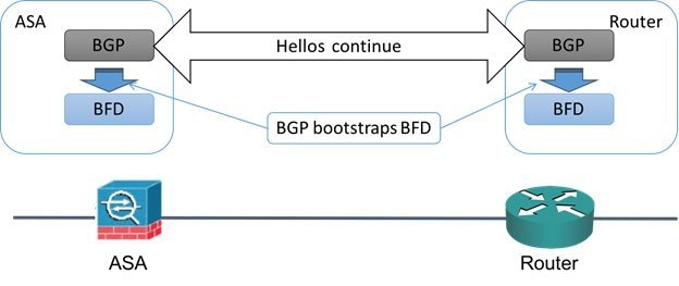
After BGP identifies its BGP neighbor, it bootstraps the BFD process with the IP address of the neighbor. BFD does not discover its peers dynamically. It relies on the configured routing protocols to tell it which IP addresses to use and which peer relationships to form.
The BFD on the router and the BFD on the ASA form a BFD control packet and start sending the packets to each other at a one-second interval until the BFD session is established. The initial control packets from either system are very similar, for example, the Vers, Diag, H, D, P, and F bits are all set to zero, and the State is set to Down. The My Discriminator field is set to a value that is unique on the transmitting device. The Your Discriminator field is set to zero because the BFD session has not yet been established. The TX and RX timers are set to the values found in the configuration of the device.
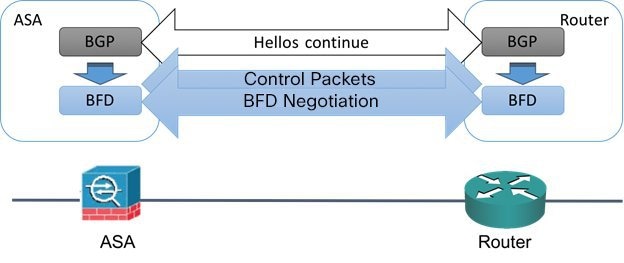
After the remote BFD device receives a BFD control packet during the session initiation phase, it copies the value of the My Discriminator field into its own Your Discriminator field and the transition from Down state to Init state and then eventually to Up state occurs. Once both systems see their own Discriminators in each other's control packets, the session is officially established.
The following illustration shows the established BFD connection.
Figure 56-2 BFD Session Established
BFD Timer Negotiation
BFD devices must negotiate the BFD timers to control and synchronize the send rate of BFD control packets.
A device needs to ensure the following before it can negotiate a BFD timer:
- That its peer device saw the packet containing the proposed timers of the local device
- That it never sends BFD control packets faster than the peer is configured to receive them
- That the peer never sends BFD control packets faster than the local system is configured to receive them
The setting of the Your Discriminator field and the H bit are sufficient to let the local device that the remote device has seen its packets during the initial timer exchange. After receiving a BFD control packet, each system takes the Required Min RX Interval and compares it to its own Desired Min TX Interval, and then takes the greater (slower) of the two values and uses it as the transmission rate for its BFD packets. The slower of the two systems determines the transmission rate.
When these timers have been negotiated, they can be renegotiated at any time during the session without causing a session reset. The device that changes its timers sets the P bit on all subsequent BFD control packets until it receives a BFD control packet with the F bit set from the remote system. This exchange of bits guards against packets that might otherwise be lost in transit.
Note![]() The setting of the F bit by the remote system does not mean that it accepts the newly proposed timers. It indicates that the remote system has seen the packets in which the timers were changed.
The setting of the F bit by the remote system does not mean that it accepts the newly proposed timers. It indicates that the remote system has seen the packets in which the timers were changed.
BFD Failure Detection
When the BFD session and timers have been negotiated, the BFD peers send BFD control packets to each other at the negotiated interval. These control packets act as a heartbeat that is very similar to IGP Hello protocol except that the rate is more accelerated.
As long as each BFD peer receives a BFD control packet within the configured detection interval (Required Minimum RX Interval), the BFD session stays up and any routing protocol associated with BFD maintains its adjacencies. If a BFD peer does not receive a control packet within this interval, it informs any clients participating in that BFD session about the failure. The routing protocol determines the appropriate response to that information. The typical response is to terminate the routing protocol peering session and reconverge and thus bypass a failed peer.
Each time a BFD peer successfully receives a BFD control packet in a BFD session, the detection timer for that session is reset to zero. Thus the failure detection is dependent on received packets and NOT when the receiver last transmitted a packet.
BFD Deployment Scenarios
The following describes how BFD operates in these specific scenarios.
Failover
In a failover scenario, BFD sessions are established and maintained between the active unit and the neighbor unit. Standby units do not maintain any BFD sessions with the neighbors. When a failover happens, the new active unit must initiate session establishment with the neighbor because session information is not synched between active and standby units.
For a graceful restart/NSF scenario, the client (BGP IPv4/IPv6) is responsible for notifying its neighbor about the event. When the neighbor receives the information, it keeps the RIB table until failover is complete. During failover, the BFD and the BGP sessions go down on the device. When the failover is complete, a new BFD session between the neighbors is established when the BGP session comes up.
Spanned EtherChannel and L2 Cluster
In a Spanned EtherChannel cluster scenario, the BFD session is established and maintained between the primary unit and its neighbor. Subordinate units do not maintain any BFD sessions with the neighbors.If a BFD packet is routed to the subordinate unit because of load balancing on the switch, the subordinate unit must forward this packet to the primary unit through the cluster link. When a cluster switchover happens, the new primary unit must initiate session establishment with the neighbor because session information is not synched between primary and subordinate units.
Individual Interface Mode and L3 Cluster
In an individual interface mode cluster scenario, individual units maintain their BFD sessions with their neighbors.
Create BFD Template
This section describes the steps required to create a BFD template policy object. The BFD template specifies a set of BFD interval values. BFD interval values as configured in the BFD template are not specific to a single interface. You can also configure authentication for single-hop and multi-hop sessions. You can enable Echo on single-hop only.
Select Manage > Policy Objects, then select BFD Template from the Object Type selector. Right-click inside the work area, then select New Object or right-click a row and select Edit Object.
|
|
|
|---|---|
The object name, which can be up to 128 characters. Object names are not case-sensitive. For more information, see Creating Policy Objects. |
|
Specify if there is a single IP hop or multiple IP hops between a BFD source and destination associated with an interface. |
|
(Optional) Select to enable echo. When enabled, echo packets are sent by the forwarding engine and forwarded back along the same path in order to perform detection. Note This is applicable only for single hop configuration mode. |
|
Specify if you want to define the interval type in microseconds or milliseconds.The default interval type is None. |
|
This section is enabled, if the Interval type is microseconds. Valid values are between 50000 and 999000 microseconds. Minimum Transmit Value - Enter the minimum transmit interval capability in microseconds. Minimum Receive Value - Enter the minimum receive interval capability microseconds. |
|
This section is enabled, if the Interval type is milliseconds. Valid values are between 50 and 999 milliseconds. Minimum Transmit Value - Enter the minimum transmit interval capability in milliseconds. Minimum Receive Value - Enter the minimum receive interval capability milliseconds. |
|
Enter the number of consecutive BFD control packets that must be missed before BFD declares that a peer is unavailable.The default value is 3. Valid values are between 3 to 50. |
|
Select to configure authentication for the BFD template and specify if you want to use an encrypted password or an unencrypted password,for the authentication. |
|
Enter a BFD password and confirm it.
|
|
Enter an authentication key ID. This is a shared key ID, that matches the key string. |
|
The category assigned to the object. Categories help you organize and identify rules and objects. See Using Category Objects. |
|
Whether to allow the object definition to be changed at the device level. For more information, see Allowing a Policy Object to Be Overridden and Understanding Policy Object Overrides for Individual Devices. If you allow device overrides, you can click the Edit button to create, edit, and view the overrides. The Overrides field indicates the number of devices that have overrides for this object. |
|
Add/ Edit BFD Map Dialog Box
The Add/ Edit BFD Map dialog box lets you create a BFD map containing destinations that you can associate with a multi-hop template. You must have a multi-hop BFD template already configured. For more information see, Create BFD Template
You can access the Add/ Edit BFD Map dialog box from the Maps tab on the BFD page. Click the Add Row button to add a new BFD map; select an existing BFD map and click the Edit Row button to edit that map.
|
|
|
|---|---|
Select a multi-hop BFD template or add a multi-hop BFD template. For more information see, Create BFD Template |
|
Select the appropriate address format for the source and destination - IPv4 or IPv6. |
|
Enter the IPv4 address for the destination and source in the appropriate fields in the x.x.x.x/prefix format. |
|
Enter the IPv6 address for the destination and source in the appropriate fields in the x:x:x:x:x:x:x:x/prefix format. |
|
This reduces the number of BFD control packets, that are sent between BFD neighbors. This slows down the asynchronous session, reduces the processing overhead and results in faster failure detection. The default value for slow timers is 1000 and valid values are between 1000 - 30000. |
Add/ Edit BFD Interface Dialog Box
The Add/ Edit BFD Interfaces dialog box lets you bind a BFD template to an interface, configure the baseline BFD session parameters per interface, and enable echo mode per interface.
You can access the Add/ Edit BFD Interface dialog box from the Interface tab on the BFD page. Click the Add Row button to add a new BFD interface; select an existing BFD interface and click the Edit Row button to edit that map.
|
|
|
|---|---|
Enter an interface name, select an interface or add an interface role. |
|
Select BFD template to select an existing single-hop BFD template or add a single-hop BFD template. Alternately, select BFD interval. For more information see, Create BFD Template |
|
Enter the minimum transmit interval capability in milliseconds.Valid values are between 50 and 999 milliseconds |
|
Enter the minimum receive interval capability milliseconds. Valid values are between 50 and 999 milliseconds |
|
Enter the number of consecutive BFD control packets that must be missed before BFD declares that a peer is unavailable.The default value is 3. Valid values are between 3 to 50. |
|
(Optional) Select to enable echo. When enabled, echo packets are sent by the forwarding engine and forwarded back along the same path in order to perform detection. |
|
Configuring OSPF
The OSPF page provides ten tabbed panels for configuring OSPF (Open Shortest Path First) routing on a firewall device. The following topics provide detailed information about enabling and configuring OSPF:
Note![]() Depending on the device version that you are configuring, some tabs might not be available.
Depending on the device version that you are configuring, some tabs might not be available.
Note![]() Beginning with ASA version 9.2(1), certain OSPF settings have changed. If you configure a shared policy that uses settings specific to ASA 9.2(1)+, you will receive a validation error if that policy is assigned to a device whose version is earlier than 9.2(1). Likewise, if you configure a shared policy that uses settings that no longer apply to ASA 9.2(1)+, you will receive a validation error if that policy is assigned to an 9.2(1)+ device.
Beginning with ASA version 9.2(1), certain OSPF settings have changed. If you configure a shared policy that uses settings specific to ASA 9.2(1)+, you will receive a validation error if that policy is assigned to a device whose version is earlier than 9.2(1). Likewise, if you configure a shared policy that uses settings that no longer apply to ASA 9.2(1)+, you will receive a validation error if that policy is assigned to an 9.2(1)+ device.
- About OSPF
- General Tab
- Area Tab
- Range Tab
- Neighbors Tab
- Redistribution Tab
- Virtual Link Tab
- Filtering Tab
- Filter Rule Tab
- Summary Address Tab
- Interface Tab
- (Device view) Select Platform > Routing > OSPF from the Device Policy selector.
- (Policy view) Select PIX/ASA/FWSM Platform > Routing > OSPF from the Policy Type selector. Select an existing policy from the Shared Policy selector, or create a new one.
About OSPF
Open Shortest Path First (OSPF) is an interior gateway routing protocol that uses link states rather than distance vectors for path selection. OSPF propagates link-state advertisements (LSAs) rather than routing table updates. Because only LSAs are exchanged, rather than entire routing tables, OSPF networks converge more quickly than RIP networks.
OSPF supports MD5 and clear-text neighbor authentication. Authentication should be used with all routing protocols whenever possible, because route redistribution between OSPF and other protocols (like RIP) can potentially be used by attackers to subvert routing information.
If NAT is used when OSPF is operating on public and private areas, and if address filtering is required, you need to run two OSPF processes—one process for the public areas and one for the private areas.
A router that has interfaces in multiple areas is called an Area Border Router (ABR). A router that acts as a gateway to redistribute traffic between routers using OSPF and routers using other routing protocols is called an Autonomous System Boundary Router (ASBR).
An ABR uses LSAs to send information about available routes to other OSPF routers. Using ABR type 3 LSA filtering, you can have separate private and public areas with the security appliance acting as an ABR. Type 3 LSAs (inter-area routes) can be filtered from one area to other. This lets you use NAT and OSPF together without advertising private networks.
Note![]() Only type 3 LSAs can be filtered. If you configure the security appliance as an ASBR in a private network, it will send type 5 LSAs describing private networks, which will be broadcast to the entire autonomous system (AS) including public areas.
Only type 3 LSAs can be filtered. If you configure the security appliance as an ASBR in a private network, it will send type 5 LSAs describing private networks, which will be broadcast to the entire autonomous system (AS) including public areas.
If NAT is employed but OSPF is only running in public areas, routes to public networks can be redistributed inside the private network, either as default or type 5 AS External LSAs. However, you need to configure static routes for the private networks protected by the security appliance. Also, you should not mix public and private networks on the same security appliance interface.
General Tab
Use the General panel on the OSPF page to enable up to two OSPF process instances. Each OSPF process has its own associated areas and networks.
Note![]() You cannot enable OSPF if you have RIP enabled.
You cannot enable OSPF if you have RIP enabled.
You can access the General panel from the OSPF Page; see Configuring OSPF for more information.
- Area Tab
- Range Tab
- Neighbors Tab
- Redistribution Tab
- Virtual Link Tab
- Filtering Tab
- Summary Address Tab
- Interface Tab
|
|
|
|---|---|
| The General tab provides two identical sections; each is used to enable one OSPF process. The following options are available in each section. |
|
Check this box to enable an OSPF process. You cannot enable an OSPF process if you have RIP enabled on the security appliance. Deselect this option to remove the OSPF process. |
|
Enter a unique numeric identifier for the OSPF process. This process ID is used internally and does not need to match the OSPF process ID on any other OSPF devices. Valid values are from 1 to 65535. |
|
Opens the OSPF Advanced Dialog Box, in which you can configure additional process-related parameters, such as Router ID, Adjacency Changes, Administrative Route Distances, Timers, and Default Information Originate settings. |
|
OSPF Advanced Dialog Box
Use the OSPF Advanced dialog box to configure settings such as the Router ID, Adjacency Changes, Administrative Route Distances, Timers, and Default Information Originate settings for an OSPF process.
Note![]() Beginning with ASA version 9.2(1), certain OSPF settings have changed. If you configure a shared policy that uses settings specific to ASA 9.2(1)+, you will receive a validation error if that policy is assigned to a device whose version is earlier than 9.2(1). Likewise, if you configure a shared policy that uses settings that no longer apply to ASA 9.2(1)+, you will receive a validation error if that policy is assigned to an 9.2(1)+ device.
Beginning with ASA version 9.2(1), certain OSPF settings have changed. If you configure a shared policy that uses settings specific to ASA 9.2(1)+, you will receive a validation error if that policy is assigned to a device whose version is earlier than 9.2(1). Likewise, if you configure a shared policy that uses settings that no longer apply to ASA 9.2(1)+, you will receive a validation error if that policy is assigned to an 9.2(1)+ device.
You can access the OSPF Advanced dialog box from the General Tab.
|
|
|
|---|---|
Displays the ID of the OSPF process you are configuring. You cannot change this value in this dialog box. |
|
|
|
|
To use a fixed router ID, select IP Address and then enter a router ID in IP address format in the Router ID field. To have the router ID automatically generated (the highest-level IP address on the security appliance is used as the router ID), select Automatic. |
|
Select this option to suppress transmission of syslog messages when the security appliance receives Type 6 (MOSPF) LSA packets. |
|
Select this option to calculate summary route costs per RFC 1583. Deselect this option to calculate summary route costs per RFC 2328. To minimize the chance of routing loops, all OSPF devices in an OSPF routing domain should have RFC compatibility set identically. This option is selected by default. |
|
These options specify the syslog messages sent when adjacency changes occur.
|
|
Settings for the administrative route distances, according to the route type.
|
|
Settings used to configure LSA arrival, LSA pacing, and throttling for ASA 9.2(1)+ devices:
– – Note For LSA throttling, the first occurrence value must be equal to or less than the minimum value and the minimum value must be equal to or less than the maximum value.
– – Note For SPF throttling, the first occurrence value must be equal to or less than the minimum value and the minimum value must be equal to or less than the maximum value. Settings used to configure LSA pacing and SPF calculation timers for device versions earlier than 9.2(1):
|
|
Settings used by an ASBR to generate a default external route into an OSPF routing domain.
– – – – |
|
| Note Non Stop Forwarding (NSF) is supported on ASA 9.3(1)+ devices in Spanned Cluster mode or Failover mode only. |
|
Enables configuration of Cisco nonstop forwarding (NSF) operations. |
|
Enables Cisco nonstop forwarding (NSF) helper mode. When an ASA has NSF enabled, it is said to be NSF-capable and will operate in graceful restart mode--the OSPF router process performs nonstop forwarding recovery due to a Route Processor (RP) switchover. By default, the neighboring ASAs of the NSF-capable ASA will be NSF-aware and will operate in NSF helper mode. When the NSF-capable ASA is performing graceful restart, the helper ASAs assist in the nonstop forwarding recovery process. If you do not want the ASA to help the restarting neighbor with nonstop forwarding recovery, clear the Enable Cisco Non Stop Forwarding Helper mode option. |
|
Cancel NSF restart when non-NSF-aware neighboring networking devices are detected (Enforce Global) |
If neighbors that are not NSF-aware are detected on a network interface during an NSF graceful restart, restart is aborted on that interface only and graceful restart will continue on other interfaces. To cancel restart for the entire OSPF process when neighbors that are not NSF-aware are detected during restart, select the Cancel NSF restart when non-NSF-aware neighboring networking devices are detected (Enforce Global) option. Note The NSF graceful restart will also be canceled for the entire process when a neighbor adjacency reset is detected on any interface or when an OSPF interface goes down. |
Enables configuration of Internet Engineering Task Force (IETF) NSF operations. |
|
Enables IETF nonstop forwarding (NSF) helper mode. When an ASA has NSF enabled, it is said to be NSF-capable and will operate in graceful restart mode--the OSPF router process performs nonstop forwarding recovery due to a Route Processor (RP) switchover. By default, the neighboring ASAs of the NSF-capable ASA will be NSF-aware and will operate in NSF helper mode. When the NSF-capable ASA is performing graceful restart, the helper ASAs assist in the nonstop forwarding recovery process. If you do not want the ASA to help the restarting neighbor with nonstop forwarding recovery, clear the Enable IETF Non Stop Forwarding Helper mode option. |
|
Enables strict link-state advertisement (LSA) checking for IETF NSF helper mode. |
|
(Optional) Specifies the length of the graceful restart interval, in seconds. The range is from 1 to 1800. The default is 120. Note For a restart interval below 30 seconds, graceful restart will be terminated. |
|
Area Tab
Use the Area tab on the OSPF page to configure OSPF areas and networks.
You can access the Area tab from the OSPF page. For more information about the OSPF page, see Configuring OSPF.
- Add/Edit Area/Area Networks Dialog Box
- Configuring OSPF
- General Tab
- Range Tab
- Neighbors Tab
- Redistribution Tab
- Virtual Link Tab
- Filtering Tab
- Summary Address Tab
- Interface Tab
|
|
|
|---|---|
The type of authentication set for the area (None, Password, or MD5). |
|
Add/Edit Area/Area Networks Dialog Box
Use the Add/Edit Area/Area Networks dialog box to define area parameters, the networks contained by the area, and the OSPF process associated with the area.
You can access the Add/Edit Area/Area Networks dialog box from the Area Tab.
Range Tab
Use the Range tab to summarize routes between areas.
You can access the Range tab from the OSPF page. For more information about the OSPF page, see Configuring OSPF.
Add/Edit Area Range Network Dialog Box
Use the Add/Edit Area Range Network dialog box to add a new entry to the Route Summarization table or to change an existing entry.
You can access the Add/Edit Area Range Network dialog box from the Range Tab.
Neighbors Tab
Use the Neighbors tab to define static neighbors. You need to define a static neighbor for each point-to-point, non-broadcast interface. You also need to define a static route for each static neighbor in the Neighbors table.
You can access the Neighbors tab from the OSPF page. For more information about the OSPF page, see Configuring OSPF.
|
|
|
|---|---|
Add/Edit Static Neighbor Dialog Box
Use the Add/Edit Static Neighbor dialog box to define a static neighbor or change information for an existing static neighbor. You must define a static neighbor for each point-to-point, non-broadcast interface.
You can access the Add/Edit Static Neighbor dialog box from the Neighbors Tab.
Redistribution Tab
Use the Redistribution tab to define the rules for redistributing routes from one routing domain to another.
You can access the Redistribution tab from the OSPF page. For more information about the OSPF page, see Configuring OSPF.
Redistribution Dialog Box
Use the Redistribution dialog box to add a redistribution rule or to edit an existing redistribution rule in the Redistribution table.
You can access the Redistribution dialog box from the Redistribution Tab.
|
|
|
|---|---|
Select the OSPF process associated with the route redistribution entry. |
|
Select the source protocol from which the routes are being redistributed. You can choose one of the following options:
|
|
The autonomous system (AS) number for the BGP or EIGRP routing process. |
|
If you have chosen OSPF as the Route Type, choose the conditions used for redistributing routes from one routing protocol to another. The routes must match the selected condition to be redistributed. You can choose one or more of the following match conditions:
|
|
The metric value for the routes being redistributed. Valid values range from 1 to 16777214. When redistributing from one OSPF process to another OSPF process on the same device, the metric will be carried through from one process to the other if no metric value is specified. When redistributing other processes to an OSPF process, the default metric is 20 when no metric value is specified. |
|
Select “1” if the metric is a Type 1 external route, “2” if the metric is a Type 2 external route. |
|
The tag value is a 32-bit decimal value attached to each external route. This is not used by OSPF itself. It may be used to communicate information between ASBRs. Valid values range from 0 to 4294967295. |
|
When selected, redistribution of subnetted routes is enabled. Deselect this check box to cause only routes that are not subnetted to be redistributed. |
|
Enter or Select a route map object to apply to the redistribution entry. |
Virtual Link Tab
Use the Virtual Link tab to create virtual links. If you add an area to an OSPF network, and it is not possible to connect the area directly to the backbone area, you need to create a virtual link. A virtual link connects two OSPF devices that have a common area, called the transit area. One of the OSPF devices must be connected to the backbone area.
You can access the Virtual Link tab from the OSPF page. For more information about the OSPF page, see Configuring OSPF.
|
|
|
|---|---|
Displays the type of authentication used by the virtual link: |
Add/Edit OSPF Virtual Link Configuration Dialog Box
Use the Add/Edit OSPF Virtual Link Configuration dialog box to define virtual links or change the properties of existing virtual links.
You can access the Add/Edit OSPF Virtual Link Configuration dialog box from the Virtual Link Tab.
|
|
|
|---|---|
Select the area shared by the neighbor OSPF devices. The selected area cannot be an NSSA or a stub area. |
|
The interval, in seconds, between hello packets sent on an interface. The smaller the hello interval, the faster topological changes are detected but the more traffic is sent on the interface. This value must be the same for all routers and access servers on a specific interface. Valid values range from 1 to 65535 seconds for ASA devices earlier than 9.2(1) and from 1 to 8192 seconds for ASA 9.2(1)+. The default value is 10 seconds. |
|
The time, in seconds, between LSA retransmissions for adjacencies belonging to the interface. When a router sends an LSA to its neighbor, it keeps the LSA until it receives the acknowledgement message. If the router receives no acknowledgement, it will resend the LSA. Be conservative when setting this value, or needless retransmission can result. The value should be larger for serial lines and virtual links. Valid values range from 1 to 65535 seconds for ASA devices earlier than 9.2(1) and from 1 to 8192 seconds for ASA 9.2(1)+. The default value is 5 seconds. |
|
The estimated time, in seconds, required to send an LSA packet on the interface. LSAs in the update packet have their ages increased by the amount specified by this field before transmission. If the delay is not added before transmission over a link, the time in which the LSA propagates over the link is not considered. The value assigned should take into account the transmission and propagation delays for the interface. This setting has more significance on very low-speed links. Valid values range from 1 to 65535 seconds for ASA devices earlier than 9.2(1) and from 1 to 8192 seconds for ASA 9.2(1)+. The default value is 1 second. |
|
The interval, in seconds, in which no hello packets are received, causing neighbors to declare a router down. Valid values range from 1 to 65535 seconds for ASA devices earlier than 9.2(1) and from 1 to 8192 seconds for ASA 9.2(1)+. The default value of this field is four times the interval set by the Hello Interval field. |
|
Contains the OSPF authentication options.
|
|
Contains the settings for entering the password when password authentication is enabled. |
|
Contains the settings for entering the MD5 keys and parameters when MD5 authentication is enabled. All devices on the interface using OSPF authentication must use the same MD5 key and ID. – – |
Add/Edit OSPF Virtual Link MD5 Configuration Dialog Box
Use the Add/Edit OSPF Virtual Link MD5 Configuration dialog box to define MD5 keys for authentication of virtual links.
You can access the Add/Edit OSPF Virtual Link MD5 Configuration dialog box from the Add/Edit OSPF Virtual Link Configuration Dialog Box.
|
|
|
|---|---|
A numerical key identifier. Valid values range from 1 to 255. |
|
Filtering Tab
Use the Filtering tab to configure the ABR Type 3 LSA filters for each OSPF process. ABR Type 3 LSA filters allow only specified prefixes to be sent from one area to another area and restricts all other prefixes. This type of area filtering can be applied out of a specific OSPF area, into a specific OSPF area, or into and out of the same OSPF areas at the same time.
OSPF ABR Type 3 LSA filtering improves your control of route distribution between OSPF areas.
Only type-3 LSAs that originate from an ABR are filtered.
You can access the Filtering tab from the OSPF page. For more information about the OSPF page, see Configuring OSPF.
Add/Edit Filtering Dialog Box
Use the Add/Edit Filtering dialog box to add new filters to the Filter table or to modify an existing filter.
You can access the Add/Edit Filtering dialog box from the Filtering Tab.
|
|
|
|---|---|
Enter or Select the appropriate prefix list object. |
|
Enter the IP address and mask of the network being filtered. |
|
Select the traffic direction to filter. Choose “Inbound” to filter LSAs coming into an OSPF area or “Outbound” to filter LSAs going out of an OSPF area. |
|
Enter a sequence number for the filter. Valid values range from 1 to 4294967294. When multiple filters apply to an LSA, the filter with the lowest sequence number is used. |
|
Select “Permit” to allow the LSA traffic or “Deny” to block the LSA traffic. |
|
Specify the minimum prefix length to be matched. The value of this setting must be greater than the length of the network mask entered in the Filtered Network field and less than or equal to the value, if present, entered in the Upper Range field. |
|
Enter the maximum prefix length to be matched. The value of this setting must be greater than or equal to the value, if present, entered in the Lower Range field, or, if the Lower Range field is left blank, greater than the length of the network mask length entered in the Filtered Network field. |
Filter Rule Tab
Use the Filter Rule tab to configure rules to filter networks received or transmitted in Open Shortest Path First (OSPF) updates.
Note![]() Filter rules are supported on ASA 9.2(1)+ only.
Filter rules are supported on ASA 9.2(1)+ only.
You can access the Filter Rule tab from the OSPF page. For more information about the OSPF page, see Configuring OSPF.
Add/Edit Filter Rule Dialog Box
Use the Add/Edit Filter Rule dialog box to add new filter rules to the Filter Rules table or to modify an existing filter rule.
Note![]() Filter rules are supported on ASA 9.2(1)+ only.
Filter rules are supported on ASA 9.2(1)+ only.
You can access the Add/Edit Filter Rule dialog box from the Filter Rule Tab.
Summary Address Tab
Use the Summary Address tab to configure summary addresses for each OSPF routing process.
Routes learned from other routing protocols can be summarized. The metric used to advertise the summary is the smallest metric of all the more specific routes. Summary routes help reduce the size of the routing table.
Using summary routes for OSPF causes an OSPF ASBR to advertise one external route as an aggregate for all redistributed routes that are covered by the address. Only routes from other routing protocols that are being redistributed into OSPF can be summarized.
You can access the Summary Address tab from the OSPF page. For more information about the OSPF page, see Configuring OSPF.
Add/Edit Summary Address Dialog Box
Use the Add/Edit Summary Address dialog box to add new entries or to modify existing entries in the Summary Address table.
You can access the Add/Edit Summary Address dialog box from the Summary Address Tab.
Interface Tab
Use the Interface tab to configure interface-specific OSPF authentication routing properties.
You can access the Interface tab from the OSPF page. For more information about the OSPF page, see Configuring OSPF.
Add/Edit Interface Dialog Box
Use the Add/Edit Interface dialog box to add OSPF authentication routing properties for an interface or to change an existing entry.
Note![]() Beginning with ASA version 9.2(1), the upper limit for acceptable entries for Hello Interval, Transmit Delay, Retransmit Interval, and Dead Interval has been reduced from 65535 seconds to 8192 seconds. If you configure a shared policy that uses a value over 8192, you will receive a validation error if that policy is assigned to an 9.2(1)+ device.
Beginning with ASA version 9.2(1), the upper limit for acceptable entries for Hello Interval, Transmit Delay, Retransmit Interval, and Dead Interval has been reduced from 65535 seconds to 8192 seconds. If you configure a shared policy that uses a value over 8192, you will receive a validation error if that policy is assigned to an 9.2(1)+ device.
You can access the Add/Edit Interface dialog box from the Interface Tab.
Configuring OSPFv3
The OSPFv3 page provides two tabbed panels for configuring OSPF (Open Shortest Path First) version 3 routing on a firewall device.
- (Device view) Select Platform > Routing > OSPFv3 from the Device Policy selector.
- (Policy view) Select PIX/ASA/FWSM Platform > Routing > OSPFv3 from the Policy Type selector. Select an existing policy from the Shared Policy selector, or create a new one.
This is the basic procedure for configuring an OSPFv3 process and assigning it to an interface on the OSPFv3 page:
1.![]() On the Process Tab:
On the Process Tab:
–![]() Specify which of the two processes you are configuring by choosing Process 1 or Process 2 from the OSPFv3 Process drop-down list.
Specify which of the two processes you are configuring by choosing Process 1 or Process 2 from the OSPFv3 Process drop-down list.
–![]() Check Enable OSPFv3 Process.
Check Enable OSPFv3 Process.
–![]() Assign a Process ID ; any positive integer between 1 and 65535.
Assign a Process ID ; any positive integer between 1 and 65535.
–![]() Use the following features as needed to define the process:
Use the following features as needed to define the process:
–![]() Advanced button, opening the OSPFv3 Advanced Properties Dialog Box.
Advanced button, opening the OSPFv3 Advanced Properties Dialog Box.
–![]() Area Tab (OSPFv3), for managing area, range, and virtual-link definitions, by means of the Add/Edit Area Dialog Box (OSPFv3), Add/Edit Range Dialog Box (OSPFv3), and Add/Edit Virtual Link Dialog Box (OSPFv3).
Area Tab (OSPFv3), for managing area, range, and virtual-link definitions, by means of the Add/Edit Area Dialog Box (OSPFv3), Add/Edit Range Dialog Box (OSPFv3), and Add/Edit Virtual Link Dialog Box (OSPFv3).
–![]() Redistribution panel, for managing route redistribution definitions by means of the Add/Edit Redistribution Dialog Box (OSPFv3).
Redistribution panel, for managing route redistribution definitions by means of the Add/Edit Redistribution Dialog Box (OSPFv3).
–![]() Summary Prefix panel, for managing summary-prefix definitions by means of the Add/Edit Summary Prefix Dialog Box (OSPFv3).
Summary Prefix panel, for managing summary-prefix definitions by means of the Add/Edit Summary Prefix Dialog Box (OSPFv3).
2.![]() On the OSPFv3 Interface Tab:
On the OSPFv3 Interface Tab:
a.![]() Use the Interface and Neighbor panels to assign the process to a specific interface, using the Add/Edit Interface Dialog Box (OSPFv3) and the Add/Edit Neighbor Dialog Box (OSPFv3).
Use the Interface and Neighbor panels to assign the process to a specific interface, using the Add/Edit Interface Dialog Box (OSPFv3) and the Add/Edit Neighbor Dialog Box (OSPFv3).
About OSPFv3
Open Shortest Path First (OSPF) is an interior gateway routing protocol that uses link states rather than distance vectors for path selection. Version 3 is basically OSPFv2 enhanced for IPv6. It is similar to OSPFv2 (see About OSPF), but it is not backward compatible. To use OSPF to route both IPv4 and IPv6v packets, it will be necessary to run both OSPFv2 and OSPFv3 concurrently. They co-exist with each other, but do not interact.
Note![]() OSPFv3 is supported on ASA 9.0+ devices operating in single-context, routed mode only. That is, multiple contexts and transparent mode are not supported.
OSPFv3 is supported on ASA 9.0+ devices operating in single-context, routed mode only. That is, multiple contexts and transparent mode are not supported.
Think of a link as being an interface on a networking device. A link-state protocol makes its routing decisions based on the states of the links that connect source and destination devices. The state of a link is a description of that interface and its relationship to its neighboring networking devices. This interface information includes the IPv6 prefix/length of the interface, the type of network it is connected to, the devices connected to that network, and so on. This information is propagated in various type of link-state advertisements (LSAs). Because only LSAs are exchanged, rather than entire routing tables, OSPF networks converge more quickly than RIP networks.
The ASA can run two processes of the OSPFv3 protocol simultaneously on different sets of interfaces. You might want to run two processes if you have interfaces that use the same IP addresses (NAT allows these interfaces to co-exist, but OSPFv3 does not allow overlapping addresses). Or you might want to run one process on the inside interface and another on the outside, redistributing a subset of routes between the two processes. Similarly, you might need to segregate private addresses from public addresses.
You can redistribute routes into an OSPFv3 routing process from another OSPFv3 routing process, a RIP routing process, or from static and connected routes configured on OSPFv3-enabled interfaces.
If NAT is employed but OSPFv3 is only running in public areas, routes to public networks can be redistributed inside the private network, either as default or type 5 AS External LSAs. However, you need to configure static routes for the private networks protected by the security appliance. Also, you should not mix public and private networks on the same security appliance interface.
Differences Between OSPFv2 and OSPFv3
The additional features provided by OSPFv3 over OSPFv2 include the following:
- Use of the IPv6 link-local address for neighbor discovery and other features.
- LSAs expressed as prefix and prefix length.
- Addition of two LSA types.
- Handling of unknown LSA types.
- Protocol processing per link.
- Removal of addressing semantics.
- Addition of flooding scope.
- Support for multiple instances per link.
- Authentication support using the IPSec ESP standard for OSPFv3 routing protocol traffic, as specified by RFC-4552.
The following are ASA OSPFv3 configuration restrictions:
- To enable OSPFv3 on a specific interface, IPv6 should be enabled on the interface and it must be named.
- Only one OSPFv3 process, with one area and one instance, can be assigned to an interface.
- The Interface neighbor entries take effect only when the OSPFv3 is enabled, and network type should be point-to-point on the specified interface.
- Interface neighbor address must be a link-local address.
- Range value in area Range table should be unique across the area.
- If the area is set to NSSA or stub, the same area cannot be set for virtual-link.
- OSPFv3 redistribution not applicable on the same OSPFv3 process.
- If used in an ASA cluster, OSPFv3 encryption should be disabled.
- The Layer 3 cluster pool is not shared between OSPFv3 and the interface.
Process Tab
Use the Process tab on the OSPFv3 page to enable and configure up to two OSPFv3 routing processes. Each OSPF process has its own associated areas and networks. For each, at minimum, create an area for OSPFv3, enable an interface for OSPFv3, then redistribute the route into the targeted OSPFv3 routing processes. Note that only single-context mode is supported.
The Process tab is on the OSPFv3 page.
- (Device view) Select Platform > Routing > OSPFv3 from the Device Policy selector.
- (Policy view) Select PIX/ASA/FWSM Platform > Routing > OSPFv3 from the Policy Type selector. Select an existing policy from the Shared Policy selector, or create a new one.
|
|
|
|---|---|
Identify which OSPFv3 process you are configuring: choose Process 1 or Process 2. You can enable one or both. |
|
Check this box to enable the chosen OSPFv3 process. Deselect this option to disable the OSPFv3 process; the process configuration information is retained should you wish to re-enable it later. |
|
Enter a unique numeric identifier for this process. The ID can be any positive integer between 1 and 65535. This process ID is used internally and does not need to match the OSPFv3 process ID on any other OSPFv3 devices. |
|
Opens the OSPFv3 Advanced Properties Dialog Box, in which you can configure additional process-related parameters, such Router ID, Adjacency Changes, Administrative Route Distances, Timers, Default Information Originate, and Passive Interface settings. |
|
Use the tabs and tables in this panel to manage area, range and virtual-link definitions. See Area Tab (OSPFv3) for more about these definitions. |
|
Use this panel to manage redistribution definitions. See Add/Edit Redistribution Dialog Box (OSPFv3) for more about these definitions. |
|
Use this panel to manage summary prefix definitions. See Add/Edit Summary Prefix Dialog Box (OSPFv3) for more about these definitions. |
OSPFv3 Advanced Properties Dialog Box
Use the OSPF Advanced dialog box to configure settings such as the Router ID, Adjacency Changes, Administrative Route Distances, Timers, and Default Information Originate settings for an OSPF process.
You can access the OSPF Advanced dialog box from the Process Tab.
|
|
|
|---|---|
This read-only field displays the ID of the OSPF process you are configuring. |
|
On a single device, choose Automatic or IP Address. (An address field appears when you choose IP Address.) If you choose Automatic, the highest-level IP address on the security appliance is used as the router ID. To use a fixed router ID, choose IP Address and enter an IPv4 address in the Router ID field. On a device cluster, choose Automatic or Cluster Pool. (An IPv4 Pool object ID field appears when you choose Cluster Pool.) If you choose Cluster Pool, enter or Select the name of the IPv4 Pool object that is to supply the Router ID address. For more information, see Add or Edit IPv4 Pool Dialog Box. |
|
Select this option to suppress transmission of syslog messages when the security appliance receives Type 6 (MOSPF) LSA packets. |
|
These options specify the syslog messages sent when adjacency changes occur:
|
|
Settings for the administrative route distances, according to the route type.
|
|
LSA and SPF throttling provide a dynamic mechanism to slow LSA updates in OSPFv3 during times of network instability, and allow faster OSPFv3 convergence by providing LSA rate limiting. The settings used to configure LSA pacing and SPF calculation timers are:
– –
– – Note For LSA throttling, if the minimum or maximum time is less than the first occurrence value, then OSPFv3 automatically corrects to the first occurrence value. Similarly, if the maximum delay specified is less than the minimum delay, then OSPFv3 automatically corrects to the minimum delay value. |
|
Settings used by an ASBR to generate a default external route into an OSPFv3 routing domain:
– – – – |
|
Passive routing helps control the advertisement of OSPFv3 routing information, and disables sending and receiving OSPFv3 routing updates on an interface. Enter or Select one or more interfaces, or interface objects, to enable passive OSPFv3 routing on those interfaces. IPv4 and IPv6 addresses are supported. |
|
| Note Non Stop Forwarding (NSF) is supported on ASA 9.3(1)+ only. |
|
Enables graceful restart helper mode. When an ASA has NSF enabled, it is said to be NSF-capable and will operate in graceful restart mode. By default, the neighboring ASAs of the NSF-capable ASA will be NSF-aware and will operate in NSF helper mode. When the NSF-capable ASA is performing graceful restart, the helper ASAs assist in the nonstop forwarding recovery process. If you do not want the ASA to help the restarting neighbor with nonstop forwarding recovery, clear the Enable graceful-restart helper option. |
|
Enables strict link-state advertisement (LSA) checking. Note When enabled, it indicates that the helper router will terminate the process of restarting the router if it detects that there is a change to a LSA that would be flooded to the restarting router, or if there is a changed LSA on the retransmission list of the restarting router when the graceful restart process is initiated. |
|
Enable graceful-restart (Use when Spanned Cluster or Failover configured) |
|
(Optional) Specifies the length of the graceful restart interval, in seconds. The range is from 1 to 1800. The default is 120. Note For a restart interval below 30 seconds, graceful restart will be terminated. |
|
Area Tab (OSPFv3)
Use the Area panel on the Process Tab of the OSPFv3 page to configure OSPFv3 areas, ranges and virtual links. The Area panel consists of three definition tables—Area, Range, and Virtual Link:
- Refer to Add/Edit Area Dialog Box (OSPFv3) for information about adding and editing Area table entries.
- Refer to Add/Edit Range Dialog Box (OSPFv3) for information about adding and editing Range table entries.
- Refer to Add/Edit Virtual Link Dialog Box (OSPFv3) for information about adding and editing Virtual Link table entries.
Refer to Using Tables for basic information about working with Security Manager tables.
You can access the Area tab from the Process Tab of the OSPFv3 page. For more information about the OSPFv3 page, see Configuring OSPFv3.
Add/Edit Area Dialog Box (OSPFv3)
Use the Add/Edit Area dialog box to define parameters for the area.
You can access the Add/Edit Area dialog box from the Area Tab (OSPFv3).
Add/Edit Range Dialog Box (OSPFv3)
Use the Add/Edit Area Range Network dialog box to add a new range to the area selected in the Area table, or to change an existing entry.
You can access the Add/Edit Range dialog box from the Range panel under the Area Tab (OSPFv3).
Add/Edit Virtual Link Dialog Box (OSPFv3)
Use the Add/Edit Virtual Link dialog box to define virtual links for the area selected in the Area table, or change the properties of existing virtual links.
You can access the Add/Edit Virtual Link dialog box from the Virtual Link panel under the Area Tab (OSPFv3).
Add/Edit Redistribution Dialog Box (OSPFv3)
Use the Add/Edit Redistribution dialog box to add a redistribution rule to this process, or to edit an existing redistribution rule.
You can access the Redistribution dialog box from the Redistribution panel under the Process Tab.
|
|
|
|---|---|
Choose the source protocol for route redistribution:
|
|
The metric value for the routes being redistributed. Valid values range from 1 to 16777214; the default is 20. When redistributing from one OSPF process to another OSPF process on the same device, the metric will be carried through from one process to the other if no metric value is specified. |
|
The metric type is the external link type associated with the default route that is advertised into the OSPFv3 routing domain. Choose None, 1, or 2, where None indicates there is no default route, 1 indicates the metric is a Type 1 external route, and 2 is a Type 2 external route. |
|
The tag is a 32-bit decimal value attached to each external route. This is not used by OSPF itself. It may be used to communicate information between other border devices. Valid values range from 0 to 4294967295. |
|
Enter or Select the name of the route map object to apply to the redistribution entry. |
|
The ID of the process to which redistribution is directed. (The Process ID is defined on the Process Tab.) This option is enabled only when OSPF is chosen as the Source Protocol. |
|
Check this box to include connected routes in the redistribution. |
|
| The conditions used for redistributing routes from one routing protocol to another. The routes must match the selected condition to be redistributed. You can choose one or more of the following match conditions. These options are enabled only when OSPF is chosen as the Source Protocol. |
|
Routes that are external to the autonomous system, but are imported into OSPF as Type 1 external routes. |
|
Routes that are external to the autonomous system, but are imported into OSPF as Type 2 external routes. |
|
Routes that are external to the autonomous system, but are imported into OSPF as Type 2 NSSA routes. |
|
Routes that are external to the autonomous system, but are imported into OSPF as Type 2 NSSA routes. |
|
Add/Edit Summary Prefix Dialog Box (OSPFv3)
Use the Add/Edit Summary Prefix dialog box to add new route-summarization entries to the selected process, or to modify existing entries.
You can access the Add/Edit Summary Prefix dialog box from the Summary Prefix panel under the Process Tab.
OSPFv3 Interface Tab
Use the Interface panel to configure interface-and neighbor-specific OSPFv3 routing properties. The Interface panel consists of two definition tables, Interface and Neighbor:
- Refer to Add/Edit Interface Dialog Box (OSPFv3) for information about adding and editing Interface table entries.
- Refer to Add/Edit Neighbor Dialog Box (OSPFv3) for information about adding and editing Neighbor table entries.
Refer to Using Tables for basic information about working with Security Manager tables.
Click the Interface tab on the OSPFv3 page to display this panel. For more information about the OSPFv3 page, see Configuring OSPFv3.
Add/Edit Interface Dialog Box (OSPFv3)
Use the Add/Edit Interface dialog box to define OSPFv3 routing properties for an individual interface, or to change an existing entry.
You can access the Add/Edit Interface dialog box from the Interface panel under the OSPFv3 Interface Tab.
|
|
|
|---|---|
The name of the interface to which this routing configuration applies. |
|
Check this box to enable OSPFv3 on the specified interface, and activate the following fields:
This feature lets you have multiple OSPFv3 processes on a single link. Received packets with other instance IDs are then ignored by this process. |
|
|
|
|
Check this box to filter outgoing LSAs. All outgoing LSAs are flooded to the interface by default. |
|
Check this box to disable the OSPFv3 MTU mismatch detection when database description (DBD) packets are received. |
|
Check this box to suppress unnecessary flooding of LSAs in stable topologies. |
|
Check this box to define this as a link to a point-to-point network; that is, a network between two routing devices. All neighbors on a point-to-point network establish adjacency and there is no designated router. This option is unavailable when the Broadcast option is selected. |
|
Check this box to define this as a link to a network with multiple routing devices. Such networks establish a designated router (DR), as well as a backup designated router (BDR), that controls LSA flooding on the network. This option is unavailable when the Point-to-point Network option is selected. |
|
The cost of sending a packet through the interface. Link cost is an arbitrary number used in shortest path first calculations. If you do not assign a value, the configured reference bandwidth divided by the interface port speed is used. (The default reference bandwidth is 40 Gb/sec.) |
|
Assign an OSPFv3 priority to this interface. Valid values for this setting range from 0 to 255. Entering 0 for this setting makes the device ineligible to become the designated router or backup designated router. This setting does not apply to interfaces that are configured as point-to-point, non-broadcast interfaces. When two routing devices connect to a network, both attempt to become the designated router. The device with the higher priority becomes the designated router. If there is a tie, the router with the higher router ID becomes the designated router. |
|
If no hello packets are received from a neighbor within this interval, that device is designated as inactive. Valid values range from 1 to 65535. The default value for this setting is four times the hello interval. |
|
If a neighboring device is inactive, it may be necessary to continue sending hello packets to that neighbor. The hello packets are sent at this reduced interval, which should be larger than the hello interval. |
|
The time, in seconds, between LSA retransmissions for adjacent neighbors. When a router sends an LSA to a neighbor, it keeps the LSA until it receives an acknowledgment. If an acknowledgment is not received within this interval, it will resend the LSA. Be conservative when setting this value, or needless retransmission can result. The value should be larger for serial lines and virtual links. Valid values range from 1 to 65535 seconds. |
|
The estimated time, in seconds, required to send an LSA packet on the interface. LSAs in the update packet have their ages increased by the amount specified by this field before transmission. If the delay is not added before transmission over a link, the time in which the LSA propagates over the link is not considered. The value assigned should take into account the transmission and propagation delays for the interface. This setting has more significance on very low-speed links. Valid values range from 1 to 65535 seconds. |
|
|
|
|
The type of authentication enabled on this interface. Choose one of the following:
|
|
Enter an IPSec identification tag used to distinguish this particular OSPFv3 interface; used in conjunction with the specified authentication and encryption rules. Valid values range from 256 to 4294967295. |
|
Enter an authentication key. The length of the key entered depends on the type of authentication chosen as the Authentication Algorithm, and whether the key is to be encrypted (when you check the Encrypt Authentication Key box): |
|
Check this box to require encryption of the specified Authentication Key for transmission. |
|
Check this box to require encryption of OSPFv3 packets. The following options are enabled. |
|
Choose the type of encryption to use:
The Key Type list is enabled only when you choose this encryption option. Choose one of these options: |
|
Enter an encryption key. The length of the key entered depends on the type of encryption chosen as the Encryption Algorithm, and whether the key is to be encrypted (when you check the Encrypt Key box):
|
|
Check this box to require encryption of the specified Encryption Key for transmission. |
|
Add/Edit Neighbor Dialog Box (OSPFv3)
You must define a static neighbor for each point-to-point, non-broadcast interface. This feature lets you broadcast OSPFv3 advertisements across an existing VPN connection without having to encapsulate the advertisements in a GRE tunnel. Note the following restrictions:
- You cannot define the same static neighbor for two different OSPFv3 processes.
- You must define a static route for each static neighbor.
Use the Add/Edit Neighbor dialog box to define a static neighbor for the interface selected in the Interface table, or to change information for an existing static neighbor.
You can access the Add/Edit Neighbor dialog box from the Neighbor panel under the OSPFv3 Interface Tab.
Configuring RIP
Routing Information Protocol (RIP) is a dynamic routing protocol, or more precisely, an interior gateway protocol that is based on distance vectors. RIP uses hop count as the metric for path selection. When RIP is enabled on an interface, the interface exchanges RIP broadcast packets with neighboring devices to dynamically learn about and advertise routes. These RIP packets contain information about the destination networks that the gateways can reach, and the number of gateways that a packet must travel through to reach those destinations.
Cisco Security Manager supports both RIP version 1 and RIP version 2. Version 1 does not send the subnet mask with the routing update; RIP version 2 sends the subnet mask with the routing update, and supports variable-length subnet masks. Additionally, RIP version 2 supports neighbor authentication when routing updates are exchanged. This authentication ensures that the security appliance receives reliable routing information from a trusted source.
Note![]() You cannot enable RIP if you have OSPF processes running.
You cannot enable RIP if you have OSPF processes running.
RIP has the following limitations:
- Cisco Security Manager cannot pass RIP updates between interfaces.
- RIP Version 1 does not support variable-length subnet masks.
- RIP has a maximum hop count of 15. A route with a hop count greater than 15 is considered unreachable.
- RIP convergence is relatively slow compared to other routing protocols.
The following information applies to RIP Version 2 only:
- If using neighbor authentication, the authentication key and key ID must be the same on all neighbor devices that provide RIP version 2 updates to the interface.
- With RIP version 2, the security appliance transmits and receives default route updates using the multicast address 224.0.0.9. In passive mode, it receives route updates at that address.
- When RIP version 2 is configured on an interface, the multicast address 224.0.0.9 is registered on that interface. When a RIP version 2 configuration is removed from an interface, that multicast address is unregistered.
Using Security Manager to Configure RIP on Security Appliances
Use the RIP page to enable the Routing Information Protocol on an interface. The settings and features available when configuring RIP depend on the type of device and OS version that you are configuring:
- To configure RIP on a PIX Firewall or ASA running an OS version earlier than 7.2, or on any FWSM, see RIP Page for PIX/ASA 6.3–7.1 and FWSM.
- To configure RIP on a PIX Firewall or ASA running OS version 7.2 or later, see RIP Page for PIX/ASA 7.2 and Later.
- Configuring Static Routes
- Configuring OSPF
- Configuring No Proxy ARP
- Configuring Routing Information Protocol – a chapter from the “Cisco IOS IP Configuration Guide, Release 12.2,” providing additional detailed information about RIP
RIP Page for PIX/ASA 6.3–7.1 and FWSM
Note![]() From version 4.17, though Cisco Security Manager continues to support PIX and FWSM features/functionality, it does not support any bug fixes or enhancements.
From version 4.17, though Cisco Security Manager continues to support PIX and FWSM features/functionality, it does not support any bug fixes or enhancements.
Use this RIP page to enable the Routing Information Protocol (RIP) on an interface in any FWSM, or in a PIX/ASA running a pre-7.2 version operating system.
The RIP table on this page lists all interfaces on which RIP is currently defined. Use the Add RIP Configuration and Edit RIP Configuration dialog boxes to create and maintain these entries. See RIP Page for PIX/ASA 6.3–7.1 and FWSM for more information.
- (Device view) Select Platform > Routing > RIP from the Device Policy selector.
- (Policy view) Select PIX/ASA/FWSM Platform > Routing > RIP from the Policy Type selector. Select an existing policy from the Shared Policy selector, or create a new one.
When creating a shared RIP policy, you must choose a Version in the Create a Policy dialog box, as follows:
When assigning a shared RIP policy, be sure to assign the appropriate RIP policy for the device. For example, you cannot assign a PIX/ASA 7.2+ RIP policy to an FWSM.
- Configuring Static Routes
- Configuring OSPF
- Configuring No Proxy ARP
- RIP Page for PIX/ASA 7.2 and Later
- Standard rules table topics:
Add/Edit RIP Configuration (PIX/ASA 6.3–7.1 and FWSM) Dialog Boxes
Note![]() From version 4.17, though Cisco Security Manager continues to support PIX and FWSM features/functionality, it does not support any bug fixes or enhancements.
From version 4.17, though Cisco Security Manager continues to support PIX and FWSM features/functionality, it does not support any bug fixes or enhancements.
Use the Add RIP Configuration and Edit RIP Configuration dialog boxes to add a RIP configuration to the security appliance, or to make changes to an existing RIP configuration. By adding a RIP configuration, you enable RIP on the specified interface. Except for their titles, the two dialog boxes are identical.
You can access the Add and Edit RIP Configuration dialog boxes from the RIP Page for PIX/ASA 6.3–7.1 and FWSM.
RIP Page for PIX/ASA 7.2 and Later
Note![]() From version 4.17, though Cisco Security Manager continues to support PIX and FWSM features/functionality, it does not support any bug fixes or enhancements.
From version 4.17, though Cisco Security Manager continues to support PIX and FWSM features/functionality, it does not support any bug fixes or enhancements.
Use this RIP page to enable and configure the Routing Information Protocol (RIP) on PIX and ASA devices running operating system 7.2 or later. The RIP page consists of these tabbed panels:
- (Device view) Select Platform > Routing > RIP from the Device Policy selector.
- (Policy view) Select PIX/ASA/FWSM Platform > Routing > RIP from the Policy Type selector. Select an existing policy from the Shared Policy selector, or create a new one.
When creating a shared RIP policy, you must choose a Version in the Create a Policy dialog box, as follows:
When assigning a shared RIP policy, be sure to assign the appropriate RIP policy for the device. For example, you cannot assign a PIX/ASA 7.2+ RIP policy to an FWSM.
RIP - Setup Tab
Use the Setup panel to define RIP on the security appliance, and to configure global RIP protocol parameters. You can only enable a single RIP process on the security appliance.
You can access the Setup tab from the RIP Page for PIX/ASA 7.2 and Later.
- RIP - Redistribution Tab
- RIP - Filtering Tab
- RIP - Interface Tab
- Chapter 56, “Configuring Routing Policies on Firewall Devices”
|
|
|
|---|---|
Define one or more networks for RIP routing. Enter IP address(es), or enter or Select the desired Network/Hosts objects (see Understanding Networks/Hosts Objects); IP addresses must not contain any subnet information. There is no limit to the number of networks you can add to the security appliance configuration. The RIP routing updates will be sent and received only through interfaces on the specified networks. Also, if the network of an interface is not specified, the interface will not be advertised in any RIP updates. |
|
Use this option to specify passive interfaces on the security appliance, and by extension the active interfaces. The device listens for RIP routing broadcasts on passive interfaces, using that information to populate its routing tables, but does not broadcast routing updates on passive interfaces. Interfaces that are not designated as passive, receive and send updates. Choose one of these options: 1. 2. 3. |
|
Use this field to specify the interfaces excluded from the passive list, or those explicitly designated as passive, depending on your choice from the Passive Interface list above:
Note You cannot specify two different RIP configurations for the same interface. |
|
Choose the RIP versions for sending and receiving RIP updates: |
|
When selected, a default route is generated for distribution, based on the Route Map you specify. |
|
Specify the route map to use for generating default routes. Note This field contains only the Route Map name. The Route Map is created and contained within a FlexConfig; see Chapter 7, “Managing FlexConfigs” for more information. |
|
When Send and Receive Version 2 is the chosen RIP Version, this option is available. When checked, automatic route summarization is enabled. Disable automatic summarization if you must perform routing between disconnected subnets. When automatic summarization is disabled, subnets are advertised. Note RIP Version 1 always uses automatic summarization—you cannot disable it. |
RIP - Redistribution Tab
Use the Redistribution panel to manage redistribution routes. These are the routes that are being redistributed from other routing processes into the RIP routing process. See Add/Edit Redistribution Dialog Box for more information.
You can access the Redistribution tab from the RIP Page for PIX/ASA 7.2 and Later.
Add/Edit Redistribution Dialog Box
Use the Add Redistribution and Edit Redistribution dialog boxes to add and edit redistribution routes on the RIP - Redistribution Tab. These are the routes that are being redistributed from other routing processes into the RIP routing process. Except for their titles, these two dialog boxes are identical.
You can access the Add and Edit Redistribution dialog boxes from the Redistribution tab on the RIP Page for PIX/ASA 7.2 and Later.
|
|
|
|---|---|
Choose the routing protocol to redistribute into the RIP routing process:
If you choose OSPF, you must also enter the OSPF Process ID and, optionally, Match criteria. |
|
If you are redistributing OSPF routes into the RIP routing process, you can select specific types of OSPF routes to redistribute. Ctrl-click to select multiple types:
Match criteria are optional. The default is match Internal, External 1, and External 2. |
|
The RIP metric type to apply to the redistributed routes. The two choices are: |
|
The metric value to be assigned; enter a value from 0 to 16. |
|
The name of a route map that must be satisfied before the route can be redistributed into the RIP routing process. Note This field contains only the route Map name. The contents of the route map are created and contained within a FlexConfig. See Chapter 7, “Managing FlexConfigs” for more information. |
RIP - Filtering Tab
Use the Filtering panel to manage filters for the RIP policy. Filters are used to limit network information in incoming and outgoing RIP advertisements. See Add/Edit Filter Dialog Box for more information.
You can access the Filtering tab from the RIP Page for PIX/ASA 7.2 and Later.
Add/Edit Filter Dialog Box
Use the Add Filter and Edit Filter dialog boxes to add and edit RIP filters on the RIP - Filtering Tab. Filters are used to limit network information in incoming and outgoing RIP advertisements. Except for their titles, these two dialog boxes are identical.
You can access the Add and Edit Filter dialog boxes from the Filtering tab on the RIP Page for PIX/ASA 7.2 and Later.
RIP - Interface Tab
Use the Interface panel to manage the interfaces configured to send and receive RIP broadcasts. See Add/Edit Interface Dialog Box for more information.
You can access the Interface tab from the RIP Page for PIX/ASA 7.2 and Later.
Add/Edit Interface Dialog Box
Use the Add Interface and Edit Interface dialog boxes to add and edit RIP interface configurations on the RIP - Interface Tab. Except for their titles, these two dialog boxes are identical.
You can access the Add and Edit Interface dialog boxes from the Interface tab on the RIP Page for PIX/ASA 7.2 and Later.
|
|
|
|---|---|
These options let you override, for this interface, the global Send versions specified on the RIP - Setup Tab. Select the appropriate boxes to specify sending updates using RIP Version 1, Version 2, or both. |
|
These options let you override the global Receive versions. Select the appropriate boxes to specify accepting updates using RIP Version 1 only, Version 2 only, or both. |
|
Choose the authentication used on this interface for RIP broadcasts: If you choose MD5 or Clear Text, you must also provide the following authentication parameters: |
Configuring Static Routes
A static route is a specific path to a particular destination network that is manually defined on the current device. Static routes are used in a variety of situations, and can be a quick and effective way to route data from one network to another when there is no dynamic route to the destination, or when use of a dynamic routing protocol is not feasible.
All routes have a value or “metric” that represents its priority of use. (This metric is also referred to as “administrative distance.”) When two or more routes to the same destination are available, devices use administrative distance to decide which route to use.
For static routes, the default metric value is one, which gives them precedence over routes from dynamic routing protocols. If you increase the metric to a value greater than that of a dynamic route, the static route operates as a back-up in the event that dynamic routing fails. For example, Open Shortest Path First (OSPF)-derived routes have a default administrative distance of 100. To configure a back-up static route that is overridden by an OSPF route, specify a metric value for the static route that is greater than 100. This is referred to as a “floating” static route.
There is a special kind of static route known as a default route, or a “zero-zero” route because all zeroes are used for both the destination address and subnet mask. The default static route serves as a catch-all gateway: if there are no matches for a particular destination in the device’s routing table, the default route is used. The default route generally includes a next-hop IP address or local exit interface.
Use the Static Route page to maintain manually defined static routes. The Static Route table on this page lists all currently defined static routes, showing for each, the name of the interface or interface role for which the route is defined, the destination network(s), the next hop gateway, the route metric, whether the route is tunneled, and whether there is service-level agreement tracking for the route. For a detailed explanation of these fields, see Add/Edit Static Route Dialog Box or Add/Edit IPv6 Static Route Dialog Box.
Static null0 Route Configuration
Typically ACLs are used for traffic filtering and they enable you to filter packets based on the information contained in their headers. In packet filtering, the ASA firewall examines packet headers to make a filtering decision, thus adding some overhead to the processing of the packets and affecting performance.
Static null 0 routing is a complementary solution to filtering. A static null0 route is used to forward unwanted or undesirable traffic into a black hole. The null interface null0, is used to create the black hole. Static routes are created for destinations that are not desirable, and the static route configuration points to the null interface. Any traffic that has a destination address that has a best match of the black hole static route is automatically dropped. Unlike with ACLs, static null0 routes do not cause any performance degradation.
The static null0 route configuration is used to prevent routing loops. BGP leverages the static null0 configuration for Remotely Triggered Black Hole routing.
- (Device view) Select Platform > Routing > Static Route or Platform > Routing > IPv6 Static Route from the Device Policy selector.
- (Policy view) Select PIX/ASA/FWSM Platform > Routing > Static Route or PIX/ASA/FWSM Platform > Routing > IPv6 Static Route from the Policy Type selector. Select an existing policy from the Shared Policy selector, or create a new one.
- Chapter 56, “Configuring Routing Policies on Firewall Devices”
- Add/Edit Static Route Dialog Box
- Add/Edit IPv6 Static Route Dialog Box
- Monitoring Service Level Agreements (SLAs) To Maintain Connectivity
- Standard rules table topics:
–![]() Table Columns and Column Heading Features
Table Columns and Column Heading Features
Add/Edit Static Route Dialog Box
The Add/Edit Static Route dialog box lets you add or edit a static route.
You can access the Add/Edit Static Route dialog box from the Static Routes page. Click the Add Row button to add a new static route; select an existing static route and click the Edit Row button to edit that route.
|
|
|
|---|---|
Enter or Select the interface to which this static route applies. Sending traffic to a Null0 interface results in dropping the packets destined to the specified network. This feature is useful in configuring Remotely Triggered Black Hole (RTBH) for BGP. For more information, see Configuring Static Routes. Note If Null0 is selected as the interface, the Gateway and Tunneled options are disabled. |
|
Enter or Select the destination network(s). You can provide one or more IP address/netmask entries, one or more Networks/Hosts objects, or a combination of both; separate the entries with commas. |
|
Enter or Select the gateway router which is the next hop for this route. You can provide an IP address, or a Networks/Hosts object. Note If an IP address from one of the security appliance’s interfaces is used as the Gateway IP address, the security appliance will resolve the designated IP address in the packet instead of resolving the Gateway IP address. |
|
The Metric is a measurement of the “expense” of a route, based on the number of hops (hop count) to the network on which a specific host resides. Hop count is the number of networks that a network packet must traverse, including the destination network, before it reaches its final destination. Because the hop count includes the destination network, all directly connected networks have a metric of 1. Enter the number of hops to the destination network. Valid values range from 1 to 255; the default value is 1. The maximum number of equal-cost (equal-metric) routes that can be defined per interface is three. You cannot add a route with the same metric on different interfaces that are on the same network. |
|
Select this option to make this a tunnel route; can be used only for a default route. You can configure only one default tunneled gateway per device. The Tunneled option is not supported in transparent mode. Available only on PIX/ASA 7.0+ devices. |
|
To monitor route availability, enter or Select name of an SLA (service level agreement) object that defines the monitoring policy. Available only on PIX/ASA 7.2+ devices. For more information on route tracking, see Monitoring Service Level Agreements (SLAs) To Maintain Connectivity. |
Add/Edit IPv6 Static Route Dialog Box
The Add/Edit IPv6 Static Route dialog box lets you add or edit an IPv6 static route. IPv6 static routes are only supported on the following devices:
- ASA 7.0 and later (Routed mode)
- ASA 8.2 and later (Transparent mode)
- FWSM 3.1 and later (Routed mode)
You can access the Add/Edit IPv6 Static Route dialog box from the IPv6 Static Route page. Click the Add Row button to add a new static route; select an existing static route and click the Edit Row button to edit that route.
Configuring Policy Objects for ASA Routing Policies
There are several policy objects that you use with ASA routing policies. This reference explains the configuration of these policy objects.
This section contains the following topics:
- Understanding Route Map Objects
- Add or Edit Policy List Object Dialog Box
- Add or Edit Prefix List Object Dialog Box
- Add or Edit Prefix List IPv6 Object Dialog Box
- Add or Edit As Path Object Dialog Boxes
- Add or Edit Community List Object Dialog Box
- Create BFD Template
Understanding Route Map Objects
You can use route maps to define the conditions for redistributing routes from one routing protocol into another, or to enable policy routing.
Route maps have many features in common with widely known ACLs. These are some of the traits common to both:
- They are an ordered sequence of individual statements, each has a permit or deny result. Evaluation of ACL or route maps consists of a list scan, in a predetermined order, and an evaluation of the criteria of each statement that matches. A list scan is aborted once the first statement match is found and an action associated with the statement match is performed.
- They are generic mechanisms—Criteria matches and match interpretation are dictated by the way that they are applied. The same route map applied to different tasks might be interpreted differently.
These are some of the differences between route maps and ACLs:
Note![]() Route maps do not support ACLs that include a user, user group, security group tag, or fully qualified domain name objects.
Route maps do not support ACLs that include a user, user group, security group tag, or fully qualified domain name objects.
- The main result from the evaluation of an ACL is a yes or no answer—An ACL either permits or denies input data. Applied to redistribution, an ACL determines if a particular route can (route matches ACLs permit statement) or can not (matches deny statement) be redistributed. Typical route maps not only permit (some) redistributed routes but also modify information associated with the route, when it is redistributed into another protocol.
- Route maps are more flexible than ACLs and can verify routes based on criteria which ACLs can not verify. For example, a route map can verify if the type of route is internal.
- Each ACL ends with an implicit deny statement, by design convention; there is no similar convention for route maps. If the end of a route map is reached during matching attempts, the result depends on the specific application of the route map. Fortunately, route maps that are applied to redistribution behave the same way as ACLs: if the route does not match any clause in a route map then the route redistribution is denied, as if the route map contained deny statement at the end.
Route maps are preferred if you intend to either modify route information during redistribution or if you need more powerful matching capability than an ACL can provide. If you simply need to selectively permit some routes based on their prefix or mask, we recommend that you use a route map to map to an ACL (or equivalent prefix list).
Note![]() You must use a standard ACL as the match criterion for your route map. Using an extended ACL will not work, and your routes will never be redistributed. We recommend that you number clauses in intervals of 10 to reserve numbering space in case you need to insert clauses in the future.
You must use a standard ACL as the match criterion for your route map. Using an extended ACL will not work, and your routes will never be redistributed. We recommend that you number clauses in intervals of 10 to reserve numbering space in case you need to insert clauses in the future.
Route maps can have permit and deny clauses. If the match criteria are met for this route map, and the permit keyword is specified, the route is redistributed as controlled by the set actions. If the match criteria are not met, and the permit keyword is specified, the next route map with the same map tag is tested. If a route passes none of the match criteria for the set of route maps sharing the same name, it is not redistributed by that set. If the match criteria are met for the route map and the deny keyword is specified, the route is not redistributed.
- If you use an ACL in a route map using a permit clause, routes that are permitted by the ACL are redistributed.
- If you use an ACL in a route map deny clause, routes that are permitted by the ACL are not redistributed.
- If you use an ACL in a route map permit or deny clause, and the ACL denies a route, then the route map clause match is not found and the next route-map clause is evaluated.
Each entry in a route map statement contains a combination of match and set clauses. The match clause defines the criteria for whether appropriate packets meet the particular policy (that is, the conditions to be met). The set clause explains how the packets should be routed once they have met the match criteria.
For each route that is being redistributed, the router first evaluates the match criteria of a clause in the route map. If the match criteria succeed, then the route is redistributed or rejected as dictated by the permit or deny clause, and some of its attributes might be modified as defined by the set clause. If the match criteria fail, then this clause is not applicable to the route, and the software proceeds to evaluate the route against the next clause in the route map. Scanning of the route map continues until a clause is found whose match clause matches the route or until the end of the route map is reached.
A match or set value in each clause can be missed or repeated several times, if one of these conditions exists:
- If several Match Clause values are present in a clause, all must succeed for a given route in order for that route to match the clause (in other words, the logical AND algorithm is applied for multiple match commands).
- If a Match Clause value refers to several objects in one command, any of the objects should match (the logical OR algorithm is applied).
- If a Match Clause value is not present, all routes match the clause.
- If a Set Value is not present in a route map permit clause, then the route is redistributed without modification of its current attributes.
Note![]() Do not configure a Set Value in a route map deny clause because the deny clause prohibits route redistribution—there is no information to modify.
Do not configure a Set Value in a route map deny clause because the deny clause prohibits route redistribution—there is no information to modify.
A route map clause without a Match or Set value performs an action. An empty permit clause allows a redistribution of the remaining routes without modification. An empty deny clause does not allow a redistribution of other routes (this is the default action if a route map is completely scanned, but no explicit match is found).
In addition to the match and set values described above, BGP provides additional match and set capabilities to route maps.
The following route-map match clauses are supported with BGP:
The following route-map set clauses are supported with BGP:
- set AS path
- set community
- set automatic tag
- set local preference
- set weight
- set origin
- set next hop
- set IP prefix list
Creating and Using Route Map Objects
When configuring a policy that requires that you identify a route map, you can select or create route map objects by clicking the Select button next to the Route Map field. To create a new route map from the Route Map Object Selector dialog box, click the Create button beneath the route map list. You can also create route map objects from the Policy Object Manager by selecting Route Map from the Object Type Selector and then clicking the New Object button. For information on the specific fields available when creating a route map object, see Add or Edit Route Map Object Dialog Boxes.
Note about the use of Route Map Objects in BGP Policies
Some of the match and set criteria used in route maps are not supported in all BGP subcommands. For example:
The following route map match criteria:
- Match Clause tab > Match first hop interface of route, Match Next Hop (IPv4 and IPv6), Match Route Source (IPv4 and IPv6), Match Metric Route Value, and Match Tag
- BGP Match Clause tab > Match AS path access lists
and the following route map set criteria:
- Set Clause tab > Metric Values (all fields) and Metric Type
- BGP Set Clause tab > Set AS path, Prepend AS path, and Prepend last AS to the AS path
are not supported in the following places:
–![]() Aggregate Address tab > Attribute Map, Advertise Map, and Suppress Map
Aggregate Address tab > Attribute Map, Advertise Map, and Suppress Map
–![]() Neighbor tab > Filtering tab
Neighbor tab > Filtering tab
–![]() Route Injection tab > Inject Map and Exist Map
Route Injection tab > Inject Map and Exist Map
Security Manager allows you to use route maps in your BGP configuration even if the route map contains unsupported match or set criteria and you will not receive a warning or error during validation. In such cases, deployment will fail and you will receive an error from the device in the following format: …%"My-Route-map" used as BGP inbound route-map, nexthop match not supported….
Please refer to the ASA documentation for guidelines on the match/set criteria supported in route maps used in BGP configuration.
Add or Edit Route Map Object Dialog Boxes
Use the Add/Edit Route Map Object dialog box to create, copy and edit route map policy objects. You can use route maps to define the conditions for redistributing routes from one routing protocol into another, or to enable policy routing.
Select Manage > Policy Objects, then select Route Map from the Object Type Selector. Right-click inside the work area and select New Object or right-click a row and select Edit Object.
- Understanding Route Map Objects
- Add or Edit Route Map Entry Dialog Box
- Policy Object Manager
- Selecting Objects for Policies
- Creating Policy Objects
- Editing Objects
- Using Category Objects
- Managing Object Overrides
- Allowing a Policy Object to Be Overridden
|
|
|
|---|---|
Enter a meaningful name for the route map object. The route map object name cannot be more than 58 characters. 
|
|
The Route Map entries that are defined in the object.
|
|
The category assigned to the object. Categories help you organize and identify rules and objects. See Using Category Objects. |
|
Whether to allow the object definition to be changed at the device level. For more information, see Allowing a Policy Object to Be Overridden and Understanding Policy Object Overrides for Individual Devices. If you allow device overrides, you can click the Edit button to create, edit, and view the overrides. The Overrides field indicates the number of devices that have overrides for this object. |
Add or Edit Route Map Entry Dialog Box
Use the Add/Edit Route Map Entry dialog box to create a new route map entry for a Route Map object or to edit an existing one.
From the Add or Edit Route Map Object Dialog Boxes, click the Add button beneath the Route Map table or select an entry in the table and click the Edit button.
- Understanding Route Map Objects
- Add or Edit Route Map Object Dialog Boxes
- Policy Object Manager
- Selecting Objects for Policies
- Creating Policy Objects
- Editing Objects
- Using Category Objects
- Managing Object Overrides
- Allowing a Policy Object to Be Overridden
|
|
|
|---|---|
A number, between 0 and 65535, that indicates the position a new route map entry will have in the list of route maps entries already configured for this route map object. |
|
Whether to redistribute a route or not. To allow redistribution for route matches, click Permit. To reject route matches from redistribution, select Deny. If you use an ACL in a route map Permit clause, routes that are permitted by the ACL are redistributed. If you use an ACL in a route map Deny clause, routes that are permitted by the ACL are not redistributed. In addition, if you use an ACL in a route map Permit or Deny clause, and the ACL denies a route, then the route map clause match is not found and the next route map clause is evaluated. |
|
| Select the Match Clause tab to choose routes to which this clause should be applied, and set the following parameters: |
|
Enable or disable matching routes that have their next hop out one of the interfaces specified. Enter or select the interfaces to match. Separate multiple entries with a comma. If you specify more than one interface, then the route can match either interface. Use the ellipsis to open the Interfaces Selector from which you can select one or more interfaces. You can also create new interface roles from the Interfaces Selector. For more information, see Understanding Interface Role Objects. |
|
|
|
|
Enable or disable matching of any routes that have a route address or match packet that is passed by one of the access lists specified. For IPv4 addresses, choose whether to use an access list or Prefix list for matching from the drop-down list and then enter or select the ACL objects or Prefix list objects you want to use for matching. Use the ellipsis to open the Access Control List Object Selector or Prefix List Object Selector from which you can select one or more objects. You can also create new objects from the object selector. For more information, see Add or Edit Access List Dialog Boxes or Add or Edit Prefix List Object Dialog Box. |
|
Enable or disable matching of the next hop address of a route. For IPv4 addresses, choose whether to use an access list or Prefix list for matching from the drop-down list and then enter or select the ACL objects or Prefix list objects you want to use for matching. Use the ellipsis to open the Access Control List Object Selector or Prefix List Object Selector from which you can select one or more objects. You can also create new objects from the object selector. For more information, see Add or Edit Access List Dialog Boxes or Add or Edit Prefix List Object Dialog Box. |
|
Enable or disable matching of the advertising source address of the route. For IPv4 addresses, choose whether to use an access list or Prefix list for matching from the drop-down list and then enter or select the ACL objects or Prefix list objects you want to use for matching. Use the ellipsis to open the Access Control List Object Selector or Prefix List Object Selector from which you can select one or more objects. You can also create new objects from the object selector. For more information, see Add or Edit Access List Dialog Boxes or Add or Edit Prefix List Object Dialog Box. |
|
|
|
|
Enable or disable matching of any routes that have a route address or match packet that is passed by one of the access lists specified. For IPv6 addresses, choose whether to use an access list or IPv6 Prefix list for matching from the drop-down list and then enter or select the ACL objects or IPv6 Prefix list objects you want to use for matching. Use the ellipsis to open the Access Control List Object Selector or IPv6 Prefix List Object Selector from which you can select one or more objects. You can also create new objects from the object selector. For more information, see Add or Edit Access List Dialog Boxes or Add or Edit Prefix List IPv6 Object Dialog Box. |
|
Enable or disable matching of the next hop address of a route. For IPv6 addresses, choose whether to use an access list or Prefix list for matching from the drop-down list and then enter or select the ACL objects or IPv6 Prefix list objects you want to use for matching. Use the ellipsis to open the Access Control List Object Selector or IPv6 Prefix List Object Selector from which you can select one or more objects. You can also create new objects from the object selector. For more information, see Add or Edit Access List Dialog Boxes or Add or Edit Prefix List IPv6 Object Dialog Box. |
|
Enable or disable matching of the advertising source address of the route. For IPv6 addresses, choose whether to use an access list or IPv6 Prefix list for matching from the drop-down list and then enter or select the ACL objects or IPv6 Prefix list objects you want to use for matching. Use the ellipsis to open the Access Control List Object Selector or IPv6 Prefix List Object Selector from which you can select one or more objects. You can also create new objects from the object selector. For more information, see Add or Edit Access List Dialog Boxes or Add or Edit Prefix List IPv6 Object Dialog Box. |
|
Enable or disable matching the metric of a route. Type the metric values to use for matching in the Match Metric Route Value field. You can enter multiple values separated by commas. This setting allows you to match any routes that have a specified metric. The metric values can range from 0 to 4294967295. |
|
Enable or disable matching the security group tag of a route. Type the tag values to use for matching in the Match Tag field. You can enter multiple values separated by commas. This setting allows you to match any routes that have a specified security group tag. The tag values can range from 0 to 4294967295. |
|
Enable or disable matching of the route type. Valid route types are External1, External2, Internal, Local, NSSA-External1, and NSSA-External2. When enabled, you can choose more than one route type from the list. |
|
| Select the Set Clause tab to modify the following information, which will be redistributed to the target protocol: Note You can specify just the Bandwidth value, all of the values, or none of the values. |
|
Metric value or Bandwidth in Kbits per second; an integer value from 0 to 4294967295. |
|
EIGRP route delay, in tens of microseconds. Valid values range from 1 to 4294967295. |
|
Likelihood of successful packet transmission for EIGRP expressed as a number from 0 to 255. The value 255 means 100 percent reliability; 0 means no reliability. |
|
Effective EIGRP bandwidth of a route expressed as a number from 1 to 255. The value 255 means 100 percent loading. |
|
Minimum MTU size of a route for EIGRP, in bytes. Valid values range from 1 to 4294967295. |
|
Select to specify the type of metric for the destination routing protocol, and choose the metric type from the drop-down list: internal, type-1, or type-2. |
|
|
|
|
Select to enable matching the BGP autonomous system path access list with the specified path access list. If you specify more than one path access list, then the route can match either path access list. Use the ellipsis to open the AS Path Object Selector from which you can select one or more AS path objects. You can also create new AS path objects from the AS Path Object Selector. For more information, see Add or Edit As Path Object Dialog Boxes. |
|
Select to enable matching the BGP community with the specified community. If you specify more than one community, then the route can match either community. Any route that does not match at least one Match community will not be advertised for outbound route maps. Use the ellipsis to open the Community List Object Selector from which you can select one or more Community List objects. You can also create new Community List objects from the Community List Object Selector. For more information, see Add or Edit Community List Object Dialog Box. To enable matching the BGP community exactly with the specified community, check the Match the specified community exactly check box. |
|
Select to configure a route map to evaluate and process a BGP policy. When multiple policy lists perform matching within a route map entry, all policy lists match on the incoming attribute only. Use the ellipsis to open the Policy List Object Selector from which you can select one or more Policy List objects. You can also create new Policy List objects from the Policy List Object Selector. For more information, see Add or Edit Policy List Object Dialog Box. |
|
| Select the BGP Set Clause tab to modify the following information, which will be redistributed to the BGP protocol: |
|
Select to modify an autonomous system path for BGP routes.
|
|
Select to set the BGP communities attributes.
Select Add to the existing communities to add the community to the already existing communities. |
|
Select to specify a preference value for the autonomous system path. Enter a value between 0 and 4294967295. |
|
Select to specify the BGP weight for the routing table. Enter a value between 0 and 65535. |
|
Select to specify the BGP origin code. Valid values are Local IGP and Incomplete. |
|
|
|
|
Select to specify the output address of packets that fulfill the match clause of a route map: |
|
|
|
|
Select to specify the output address of packets that fulfill the match clause of a route map:
|
|
|
|
|
Select to set an IPv4 prefix list. Use the ellipsis to open the Prefix List Object Selector from which you can select one or more Prefix List objects. You can also create new Prefix List objects from the Prefix List Object Selector. For more information, see Add or Edit Prefix List Object Dialog Box. |
|
Select to set an IPv6 prefix list. Use the ellipsis to open the Prefix List Object IPv6 Selector from which you can select one or more IPv6 Prefix List objects. You can also create new IPv6 Prefix List objects from the Prefix List Object Selector. For more information, see Add or Edit Prefix List IPv6 Object Dialog Box. |
|
| Policy Based Routing (PBR) Tab Click the Policy Based Routing tab to define policy for traffic flows, and lessening reliance on routes derived from routing protocols. PBR gives you more control over routing by extending and complementing the existing mechanisms provided by routing protocols. PBR allows you to set the IP precedence. It also allows you to specify a path for certain traffic, such as priority traffic over a high-cost link. |
|
Check the Set default next-hop IPv4 address check box to indicate where to output packets that pass a match clause of a route map for policy routing. In the IPv4 Address enter the destination address. |
|
Check the Set default next-hop IPv6 address check box to indicate where to output packets that pass a match clause of a route map for policy routing. In the IPv6 Address enter the destination address. |
|
Check the Recursively find and set next-hop IP address check box and specify an IP address in the IPv4 Address field. In this case, the next-hop IP address need not be on a directly connected subnet. |
|
Check the Set interfaces check box and select a destination interface from the Interfaces Selector dialog box. |
|
Check the Set null0 interface as the default interface check box, if there is a need to completely black hole or drop some traffic. |
|
Check the Set do-not-fragment bit to either 1or 0 and then select the appropriate radio button. |
|
Check the Set differential service code point (DSCP) value in QoS bits for IPv4 packets check box and either enter a value between 0 and 63 or select a value from the Select Value drop-down list. |
|
Set Differential Service Code point (DSCP) value in QOS bits for IPv6 packets |
Check the Set differential service code point (DSCP) value in QoS bits for IPv6 packets check box and either enter a value between 0 and 63 or select a value from the Select Value drop-down list. |
Add or Edit Policy List Object Dialog Box
Use the Add/Edit Policy List Object dialog box to create, copy, and edit policy list policy objects. You can create policy list objects to use when you are configuring route maps (see Understanding Route Map Objects).
When a policy list is referenced within a route map, all of the match statements within the policy list are evaluated and processed. Two or more policy lists can be configured with a route map. A policy list can also coexist with any other preexisting match and set statements that are configured within the same route map but outside of the policy list. When multiple policy lists perform matching within a route map entry, all policy lists match on the incoming attribute only.
Select Manage > Policy Objects, then select Policy List from the Object Type Selector. Right-click inside the work area and select New Object or right-click a row and select Edit Object.
- Understanding Route Map Objects
- Policy Object Manager
- Selecting Objects for Policies
- Creating Policy Objects
- Editing Objects
- Using Category Objects
- Managing Object Overrides
- Allowing a Policy Object to Be Overridden
|
|
|
|---|---|
The name of the object. Object names are not case-sensitive. For more information, see Creating Policy Objects.
|
|
|
|
|
Whether to permit access for matching conditions or not. Note The Action for a policy list object cannot be changed after the initial creation of the policy list object. |
|
Select to distribute routes that have their next hop out of one of the interfaces specified. Enter or select the interfaces to match. Separate multiple entries with a comma. If you specify more than one interface, then the route can match either interface. Use the ellipsis to open the Interfaces Selector from which you can select one or more interfaces. You can also create new interface roles from the Interfaces Selector. For more information, see Understanding Interface Role Objects. |
|
Select to redistribute any routes that have a destination address that is permitted by a standard access list or prefix list. Choose whether to use an Access List or Prefix List for matching from the drop-down list and then enter or select the ACL objects or Prefix list objects you want to use for matching. Use the ellipsis to open the Access Control List Object Selector or Prefix List Object Selector from which you can select one or more objects. You can also create new objects from the object selector. For more information, see Add or Edit Access List Dialog Boxes or Add or Edit Prefix List Object Dialog Box. |
|
Select to redistribute any routes that have a next hop router address passed by one of the access lists or prefix lists specified. Choose whether to use an Access List or Prefix List for matching from the drop-down list and then enter or select the ACL objects or Prefix list objects you want to use for matching. Use the ellipsis to open the Access Control List Object Selector or Prefix List Object Selector from which you can select one or more objects. You can also create new objects from the object selector. For more information, see Add or Edit Access List Dialog Boxes or Add or Edit Prefix List Object Dialog Box. |
|
Select to redistribute routes that have been advertised by routers and access servers at the address specified by the access lists or prefix list. Choose whether to use an Access List or Prefix List for matching from the drop-down list and then enter or select the ACL objects or Prefix list objects you want to use for matching. Use the ellipsis to open the Access Control List Object Selector or Prefix List Object Selector from which you can select one or more objects. You can also create new objects from the object selector. For more information, see Add or Edit Access List Dialog Boxes or Add or Edit Prefix List Object Dialog Box. |
|
|
|
|
Select to match a BGP autonomous system path. If you specify more than one AS path, then the route can match either AS path. Use the ellipsis to open the AS Path Object Selector from which you can select one or more AS path objects. You can also create new AS path objects from the AS Path Object Selector. For more information, see Add or Edit As Path Object Dialog Boxes. |
|
Select to enable matching the BGP community with the specified community. If you specify more than one community, then the route can match either community. Use the ellipsis to open the Community List Object Selector from which you can select one or more Community List objects. You can also create new Community List objects from the Community List Object Selector. For more information, see Add or Edit Community List Object Dialog Box. To enable matching the BGP community exactly with the specified community, check the exact-match check box. |
|
Enable or disable matching the metric of a route. Type the metric values to use for matching in the Match Metric field. You can enter multiple values separated by commas. This setting allows you to match any routes that have a specified metric. The metric values can range from 0 to 4294967295. |
|
Enable or disable matching the security group tag of a route. Type the tag values to use for matching in the Match Tag field. You can enter multiple values separated by commas. This setting allows you to match any routes that have a specified security group tag. The tag values can range from 0 to 4294967295. |
|
The category assigned to the object. Categories help you organize and identify rules and objects. See Using Category Objects. |
|
Whether to allow the object definition to be changed at the device level. For more information, see Allowing a Policy Object to Be Overridden and Understanding Policy Object Overrides for Individual Devices. If you allow device overrides, you can click the Edit button to create, edit, and view the overrides. The Overrides field indicates the number of devices that have overrides for this object. |
|
Add or Edit Prefix List Object Dialog Box
Use the Add/Edit Prefix List Object dialog box to create, copy and edit prefix list policy objects. You can create prefix list objects to use when you are configuring route maps (see Understanding Route Map Objects), policy maps (see Add or Edit Policy List Object Dialog Box), OSPF Filtering (see Add/Edit Filtering Dialog Box), or BGP Neighbor Filtering (see Add/Edit Neighbor Dialog Box).
Area Border Router (ABR) type 3 link-state advertisement (LSA) filtering extends the capability of an ABR that is running OSPF to filter type 3 LSAs between different OSPF areas. Once a prefix list is configured, only the specified prefixes are sent from one OSPF area to another OSPF area. All other prefixes are restricted to their OSPF area. You can apply this type of area filtering to traffic going into or coming out of an OSPF area, or to both the incoming and outgoing traffic for that area.
When multiple entries of a prefix list match a given prefix, the entry with the lowest sequence number is used. For efficiency, you may want to put the most common matches or denials near the top of the list by manually assigning them a lower sequence number.
Select Manage > Policy Objects, then select Prefix List from the Object Type Selector. Right-click inside the work area and select New Object or right-click a row and select Edit Object.
- Add or Edit Prefix List Entry Dialog Box
- Understanding Route Map Objects
- Add or Edit Policy List Object Dialog Box
- Policy Object Manager
- Selecting Objects for Policies
- Creating Policy Objects
- Editing Objects
- Using Category Objects
- Managing Object Overrides
- Allowing a Policy Object to Be Overridden
|
|
|
|---|---|
The object name, which can be up to 128 characters. Object names are not case-sensitive. For more information, see Creating Policy Objects.
|
|
The prefix list entries that are defined in the object.
|
|
The category assigned to the object. Categories help you organize and identify rules and objects. See Using Category Objects. |
|
Whether to allow the object definition to be changed at the device level. For more information, see Allowing a Policy Object to Be Overridden and Understanding Policy Object Overrides for Individual Devices. If you allow device overrides, you can click the Edit button to create, edit, and view the overrides. The Overrides field indicates the number of devices that have overrides for this object. |
Add or Edit Prefix List Entry Dialog Box
Use the Add/Edit Prefix List Entry dialog box to create a new prefix list entry or edit an existing one.
From the Add or Edit Prefix List Object Dialog Box, click the Add button beneath the Prefix List table or select an entry in the table and click the Edit button.
Add or Edit Prefix List IPv6 Object Dialog Box
Use the Add/Edit Prefix List IPv6 Object dialog box to create, copy and edit IPv6 prefix list policy objects. You can create IPv6 prefix list objects to use when you are configuring route maps (see Understanding Route Map Objects), policy maps (see Add or Edit Policy List Object Dialog Box), OSPF Filtering (see Add/Edit Filtering Dialog Box), or BGP Neighbor Filtering (see Add/Edit Neighbor Dialog Box).
Area Border Router (ABR) type 3 link-state advertisement (LSA) filtering extends the capability of an ABR that is running OSPF to filter type 3 LSAs between different OSPF areas. Once a prefix list is configured, only the specified prefixes are sent from one OSPF area to another OSPF area. All other prefixes are restricted to their OSPF area. You can apply this type of area filtering to traffic going into or coming out of an OSPF area, or to both the incoming and outgoing traffic for that area.
When multiple entries of a prefix list match a given prefix, the entry with the lowest sequence number is used. For efficiency, you may want to put the most common matches or denials near the top of the list by manually assigning them a lower sequence number.
Select Manage > Policy Objects, then select Prefix ListIPv6 from the Object Type Selector. Right-click inside the work area and select New Object or right-click a row and select Edit Object.
- Add or Edit IPv6 Prefix List Entry Dialog Box
- Understanding Route Map Objects
- Add or Edit Policy List Object Dialog Box
- Policy Object Manager
- Selecting Objects for Policies
- Creating Policy Objects
- Editing Objects
- Using Category Objects
- Managing Object Overrides
- Allowing a Policy Object to Be Overridden
|
|
|
|---|---|
The IPv6 Prefix List object name, which can be up to 128 characters. Object names are not case-sensitive. For more information, see Creating Policy Objects.
|
|
The IPv6 prefix list entries that are defined in the object.
|
|
The category assigned to the object. Categories help you organize and identify rules and objects. See Using Category Objects. |
|
Whether to allow the object definition to be changed at the device level. For more information, see Allowing a Policy Object to Be Overridden and Understanding Policy Object Overrides for Individual Devices. If you allow device overrides, you can click the Edit button to create, edit, and view the overrides. The Overrides field indicates the number of devices that have overrides for this object. |
Add or Edit IPv6 Prefix List Entry Dialog Box
Use the Add/Edit IPv6 Prefix List Entry dialog box to create a new IPv6 prefix list entry or edit an existing one.
From the Add or Edit Prefix List IPv6 Object Dialog Box, click the Add button beneath the Prefix List table or select an entry in the table and click the Edit button.
Add or Edit As Path Object Dialog Boxes
Use the Add/Edit As Path Object dialog box to create, copy and edit autonomous system (AS) path policy objects. You can create AS path objects to use when you are configuring route maps (see Understanding Route Map Objects), policy maps (see Add or Edit Policy List Object Dialog Box), or BGP Neighbor Filtering (see Add/Edit Neighbor Dialog Box).
An AS path filter allows you to filter the routing update message by using access lists and look at the individual prefixes within an update message. If a prefix within the update message matches the filter criteria then that individual prefix is filtered out or accepted depending on what action the filter entry has been configured to carry out.
Note![]() AS path object names must be a unique integer from 1-500. If an AS path object is discovered from a device or configuration file that uses the same name as an existing AS path object, the AS path object on Security Manager will be overwritten regardless of the Allow Device Override for Discovered Policy Objects setting on the Security Manager Administration - Discovery page.
AS path object names must be a unique integer from 1-500. If an AS path object is discovered from a device or configuration file that uses the same name as an existing AS path object, the AS path object on Security Manager will be overwritten regardless of the Allow Device Override for Discovered Policy Objects setting on the Security Manager Administration - Discovery page.
Select Manage > Policy Objects, then select As Path from the Object Type Selector. Right-click inside the work area and select New Object or right-click a row and select Edit Object.
- Add or Edit As Path Entry Dialog Box
- Understanding Route Map Objects
- Add or Edit Policy List Object Dialog Box
- Policy Object Manager
- Selecting Objects for Policies
- Creating Policy Objects
- Editing Objects
- Using Category Objects
- Managing Object Overrides
- Allowing a Policy Object to Be Overridden
|
|
|
|---|---|
Enter a name for the AS Path Filter. Specify a unique value between 1 and 500. |
|
The AS path entries that are defined in the object.
|
|
The category assigned to the object. Categories help you organize and identify rules and objects. See Using Category Objects. |
|
Whether to allow the object definition to be changed at the device level. For more information, see Allowing a Policy Object to Be Overridden and Understanding Policy Object Overrides for Individual Devices. If you allow device overrides, you can click the Edit button to create, edit, and view the overrides. The Overrides field indicates the number of devices that have overrides for this object. |
Add or Edit As Path Entry Dialog Box
Use the Add/Edit As Path Entry dialog box to create a new autonomous system (AS) path entry or edit an existing one.
From the Add or Edit As Path Object Dialog Boxes, click the Add Row button beneath the As Path table or select an entry and click the Edit Row button.
|
|
|
|---|---|
Select the Permit or Deny radio button to indicate the redistribution access. |
|
Specify the regular expression that defines the AS path filter. For information on the metacharacters you can use to build regular expressions, see Metacharacters Used to Build Regular Expressions. |
Add or Edit Community List Object Dialog Box
Use the Add/Edit Community List Object dialog box to create, copy and edit community list policy objects. You can create community list objects to use when you are configuring route maps (see Understanding Route Map Objects) or policy maps (see Add or Edit Policy List Object Dialog Box).
A community is a group of destinations that share some common attribute. You can use community lists to create groups of communities to use in a match clause of a route map. Just like an access list, a series of community lists can be created. Statements are checked until a match is found. As soon as one statement is satisfied, the test is concluded.
Select Manage > Policy Objects, then select Community List from the Object Type Selector. Right-click inside the work area and select New Object or right-click a row and select Edit Object.
- Add or Edit Community List Entry Dialog Box
- Understanding Route Map Objects
- Add or Edit Policy List Object Dialog Box
- Policy Object Manager
- Selecting Objects for Policies
- Creating Policy Objects
- Editing Objects
- Using Category Objects
- Managing Object Overrides
- Allowing a Policy Object to Be Overridden
|
|
|
|---|---|
The object name, which can be up to 128 characters. Object names are not case-sensitive. For more information, see Creating Policy Objects. |
|
The community list entries that are defined in the object.
|
|
The category assigned to the object. Categories help you organize and identify rules and objects. See Using Category Objects. |
|
Whether to allow the object definition to be changed at the device level. For more information, see Allowing a Policy Object to Be Overridden and Understanding Policy Object Overrides for Individual Devices. If you allow device overrides, you can click the Edit button to create, edit, and view the overrides. The Overrides field indicates the number of devices that have overrides for this object. |
Add or Edit Community List Entry Dialog Box
Use the Add/Edit Community List Entry dialog box to create a new community list entry or edit an existing one.
From the Add or Edit Community List Object Dialog Box, click the Add button beneath the Community List table or select an entry in the table and click the Edit button.
|
|
|
|---|---|
Select the Standard or Expanded radio button to indicate the community rule type. Note You cannot have entries using Standard and entries using Expanded community rule types in the same Community List object. |
|
Select the Permit or Deny radio button to indicate the redistribution access. |
|
Specify a community number. Valid values can be from 1 to 4294967295 or from 0:1 to 65534:65535. |
|
Select to specify the Internet well-known community. Routes with this community are advertised to all peers (internal and external). |
|
Select to specify the no-advertise well-known community. Routes with this community are not advertised to any peer (internal or external). |
|
Select to specify the no-export well-known community. Routes with this community are advertised to only peers in the same autonomous system or to only other sub-autonomous systems within a confederation. These routes are not advertised to external peers. |
|
For an expanded community list, specify the regular expression. For information on the metacharacters you can use to build regular expressions, see Metacharacters Used to Build Regular Expressions. |
 Feedback