Overview

This document explains how to install Cisco Security Management Suite (Security Manager) in a high availability (HA) or disaster recovery (DR) environment. The Security Manager HA/DR solution is based on Veritas Storage Foundation and High Availability solutions. The Security Manager HA/DR solutions described in this guide support the following applications:

  • Security Manager 4.29

The HA solution supports both local redundancy (HA) and geographic redundancy (DR) configurations.


Note


Cross-launching the Cisco Prime Security Manager (PRSM) application is supported in both HA and DR configurations; however, seamless, direct access to PRSM from Security Manager using the “single sign-on” (SSO) feature is only supported in HA mode.

Note


From version 4.21 onwards, Cisco Security Manager terminates whole support, including support for any bug fixes or enhancements, for all Aggregation Service Routers, Integrated Service Routers, Embedded Service Routers, and any device operating on Cisco IOS software, including the following devices:

  • Cisco Catalyst 6500 and 7600 Series Firewall Services Modules ( EOL8184 )

  • Cisco Catalyst 6500 Series Intrusion Detection System Services Module 2 ( EOL8843 )

  • Cisco Intrusion Prevention System: IPS 4200, 4300, and 4500 Series Sensors ( EOL9916 )

  • Cisco SR 500 Series Secure Routers ( EOL7687 , EOL7657 )

  • PIX Firewalls ( EOL )


This chapter covers the following sections:

Local Redundancy (HA) Process Overview

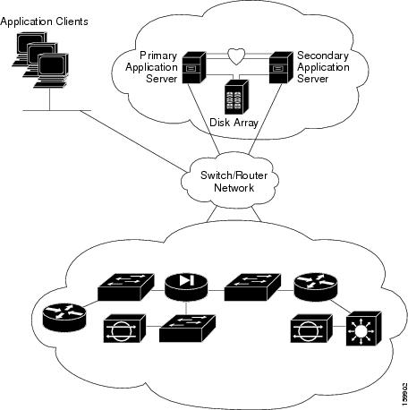
The local redundancy configuration provides an automatic failover solution in the event of software or hardware failures without the need to reconfigure IP addresses or DNS entries on your switched/routed network.

The figure illustrates the local redundancy HA configuration.


Note


The servers in the figure optionally contain mirrored internal boot disks. We recommend that they be the same make, model, and storage capacity. We recommend a fault-tolerant switched/routed network for communicating with the HA servers.
Figure 1. Local Redundancy HA Configuration

Local Redundancy (HA) Configuration Steps

The following table lists the steps required to configure a locally redundant installation of Cisco Security Manager.

Procedure

  Command or Action Purpose

Step 1

Make physical connections.

Making Ethernet Connections

Step 2

Install Microsoft Windows Server and all necessary drivers.

Installing Microsoft Windows Server

Step 3

Make storage connections.

Connecting the Servers to External Storage

Step 4

Install and configure the Veritas products and components.

Installing Veritas Products

Step 5

Mirror the boot disk.

Mirroring the Boot Disk (Optional)

Step 6

Setup required volumes on the shared array.

Veritas Volume Manager Configuration Tasks

Step 7

Install Cisco Security Manager on the shared volume on the primary server.

Installing Security Manager

Step 8

Install Cisco Security Manager on the spare (dummy) volume on the secondary server.

Installing Security Manager

Step 9

Update permissions on secondary server.

Updating Permissions on the Working Volume

Step 10

Create and configure clusters.

Veritas Cluster Server Tasks

Geographic Redundancy (DR) Process Overview

The geographic redundancy configuration provides disaster recovery by replicating application data between two sites. Failover between sites can be initiated manually or performed automatically.

The figure illustrates a geographic redundancy (DR) configuration.


Note


The servers in the figure optionally contain mirrored internal boot disks. We recommend that they be the same make, model, and storage capacity. We recommend a fault-tolerant switched/routed network for communicating with the servers.
Figure 2. Geographic Redundancy (DR) Configuration

Geographic Redundancy (DR) Configuration Steps

The following table lists the steps required to configure a geographically redundant installation of Cisco Security Manager.

Procedure

  Command or Action Purpose

Step 1

Make physical connections.

Making Ethernet Connections

Step 2

Install Microsoft Windows Server and all necessary drivers.

Installing Microsoft Windows Server

Step 3

Make storage connections.

Connecting the Servers to External Storage

Step 4

Install and configure the Veritas products and components.

Installing Veritas Products

Step 5

Mirror the boot disk.

Mirroring the Boot Disk (Optional)

Step 6

Setup required volumes on the shared array.

Veritas Volume Manager Configuration Tasks

Step 7

Install Cisco Security Manager on the shared volume on the primary server.

Installing Security Manager

Step 8

Install Cisco Security Manager on the spare (dummy) volume on the secondary server.

Installing Security Manager

Step 9

Configure replication.

Veritas Volume Replicator Tasks

Step 10

Update permissions on secondary server.

Updating Permissions on the Working Volume

Step 11

Create and configure clusters.

Veritas Cluster Server Tasks

Veritas Products

The Security Manager HA/DR solutions described in this document are based on Veritas products. This section gives a brief summary of each specific Veritas application.

  • Veritas Storage Foundation for Windows (VSFW)

    VSFW provides volume management technology, quick recovery, and fault tolerant capabilities to Windows enterprise computing environments. VSFW provides the foundation for VCS and VVR.

  • Veritas Cluster Server (VCS)

    VCS is a clustering solution for reducing application downtime. The Global Cluster Option (GCO) for VCS supports managing multiple clusters (such as used in a DR configuration).

  • Veritas Volume Replicator (VVR)

    VVR provides a foundation for continuous data replication over IP networks, enabling rapid and reliable recovery of critical applications at remote recovery sites.

  • Veritas Enterprise Administrator (VEA GUI) console

    The VEA GUI console window provides a graphical way to view and manipulate all the storage objects in your system.

  • Cluster Manager (Java Console)

    Cluster Manager (Java Console) offers complete administration capabilities for your cluster. Use the different views in the Java Console to monitor clusters and VCS objects, including service groups, systems, resources, and resource types:

    • Cluster Monitor

      Cluster Monitor displays general information about actual or simulated clusters. Use Cluster Monitor to log on to and off of a cluster, view summary information on various VCS objects, customize the display, use VCS Simulator, and exit Cluster Manager.

    • Cluster Explorer

      Cluster Explorer is the main window for cluster administration. From this window, you can view the status of VCS objects and perform various operations.