Cloud Service Assurance for Virtualized Multiservice Data Center Design Guide
Bias-Free Language
The documentation set for this product strives to use bias-free language. For the purposes of this documentation set, bias-free is defined as language that does not imply discrimination based on age, disability, gender, racial identity, ethnic identity, sexual orientation, socioeconomic status, and intersectionality. Exceptions may be present in the documentation due to language that is hardcoded in the user interfaces of the product software, language used based on RFP documentation, or language that is used by a referenced third-party product. Learn more about how Cisco is using Inclusive Language.
- Updated:
- April 27, 2013
Chapter: VMDC System Overview
VMDC System Overview
Cloud Service Assurance for VMDC (CLSA VMDC) is the service assurance system used to monitor Cisco VMDC-based cloud deployments. This chapter provides a brief overview of the VMDC system and its components.
The VMDC system is the Cisco reference architecture for Infrastructure as a Service (IaaS) cloud deployments. This Cisco IaaS cloud architecture is designed around a set of modular Data Center (DC) components consisting of building blocks of resources called pods. A pod, or Point of Delivery, comprises the Cisco Unified Computing System (UCS), SAN and NAS storage arrays, Access (switching) layers, Aggregation (switching and routing) layers connecting into the Data Center Service Node (DSN)-based Services layer, and multiple 10 GE fabric using highly scalable Cisco network switches and routers.
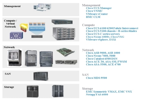
The VMDC system is built around the UCS, Nexus 1000V, Nexus 5000 and Nexus 7000 switches, Multilayer Director Switch (MDS), Aggregation Services Router (ASR) 9000, ASR 1000, Adaptive Security Appliance (ASA) or Adaptive Security Appliance Services Module (ASASM), Catalyst 6500 DSN, Application Control Engine (ACE), Nexus 1000V, Virtual Security Gateway (VSG), VMware vSphere, EMC VMAX/VNX, and NetApp FAS storage arrays. Cloud service orchestration is currently provided by the BMC Cloud Lifecycle Management (CLM) suite, and in the future, by Cisco Intelligent Automation for Cloud (CIAC).
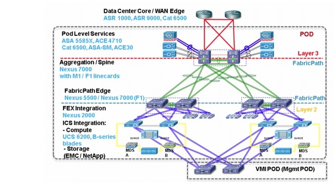
Figure 2-1 provides a synopsis of the functional infrastructure components comprising the VMDC system.
Figure 2-1 VMDC Infrastructure Components
This chapter presents the following topics:
VMDC Modular Components
The VMDC system architecture provides a scalable solution that can address the needs of Enterprise and Service Provider cloud data centers. This architecture enables customers to select the design that best suits their immediate needs while providing a solution that can scale to meet future needs without retooling or redesigning the DC. This scalability is achieved using a hierarchical design with two different modular building blocks, pod and Integrated Compute and Storage (ICS) stack.
Point of Delivery (Pod)
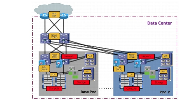
The modular DC design starts with a basic infrastructure module called a pod, which is a logical repeatable construct with predictable infrastructure characteristics and deterministic functions. A pod identifies a modular unit of DC components and enables customers to add network, compute, and storage resources incrementally. This modular architecture provides a predictable set of resource characteristics (network, compute, and storage resource pools and power and space consumption) per unit that are added repeatedly as needed.
In this design, the Aggregation layer switch pair, Services layer nodes, and one or more integrated compute stacks are contained within a pod. The pod connects to the Core layer devices in the DC. To scale a DC, additional pods can be deployed and connected to the Core layer devices.
Figure 2-2 illustrates how pods can be used to scale compute, network, and storage in predictable increments within the DC.
Figure 2-2 VMDC Pods for Scaling the Data Center
Integrated Compute and Storage (ICS) Stack
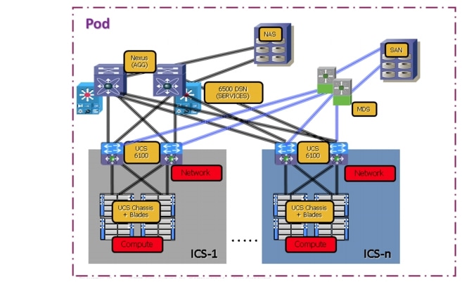
The second modular building block used is a generic ICS based on existing models, such as the VCE Vblock or NetApp FlexPod infrastructure packages. The VMDC architecture is not limited to a specific ICS definition, but can be extended to include other compute and storage stacks. An ICS can include network, compute, and storage resources in a repeatable unit. In this document, the Access layer switch pair, storage, and compute resources are contained within an ICS. To scale a pod, providers can add additional integrated compute stacks and can continue to scale in this manner until the resources reach the pod design limit.
Figure 2-3 illustrates how integrated compute stacks can be used to scale the pod.
Figure 2-3 VMDC ICS for Scaling the Data Center
VMDC System Architecture
The VMDC system utilizes a hierarchical network design for High Availability (HA) and scalability. The hierarchical or layered DC design uses redundant switches at each layer of the network topology for device-level failover that creates a highly available transport between end nodes using the network. DC networks often require additional services beyond basic packet forwarding, such as Server Load Balancing (SLB), firewall, and intrusion prevention. These services might be introduced as modules populating a slot of one of the switching nodes in the network or as stand-alone appliance devices. Each service approach also supports the deployment of redundant hardware to preserve High Availability (HA) standards set by the network topology. This layered approach is the basic foundation of the VMDC design to provide scalability, performance, flexibility, resiliency, and service assurance. VLANs and Virtual Routing and Forwarding (VRF) instances are used to provide tenant isolation within the DC architecture, and routing protocols within the VRF instances are utilized to interconnect the different networking and service devices.
The VMDC 2.2, 2.3, and 3.0 releases are the latest released versions of this architecture. This section provides a brief synopsis of the VMDC 2.2, 2.3, and 3.0 systems.
For detailed information on the VMDC 2.2 system architecture, refer to the following documents:
•![]() VMDC 2.2 Implementation Guide
VMDC 2.2 Implementation Guide
For detailed information on the VMDC 2.3 system architecture, refer to the following documents:
•![]() VMDC 2.3 Implementation Guide
VMDC 2.3 Implementation Guide
For detailed information on the VMDC 3.0 system architecture, refer to the following documents:
•![]() VMDC 3.0 Implementation Guide
VMDC 3.0 Implementation Guide

Note ![]() Information on previous VMDC system releases can be found at VMDC System Releases.
Information on previous VMDC system releases can be found at VMDC System Releases.
Note ![]() While the CLSA VMDC Design and Implementation Guide (DIG) references the VMDC 2.2, 2.3, and 3.0 systems, previous versions of the VMDC system are also supported. The CLSA VMDC system also supports other DC designs, as well as the VCE Vblock and NetApp FlexPod stacks.
While the CLSA VMDC Design and Implementation Guide (DIG) references the VMDC 2.2, 2.3, and 3.0 systems, previous versions of the VMDC system are also supported. The CLSA VMDC system also supports other DC designs, as well as the VCE Vblock and NetApp FlexPod stacks.
The VMDC 2.2, 2.3, and 3.0 systems utilize a hierarchical multi-tenant DC architecture based on either VRF-Lite or FabricPath to provide secure separation between tenants. Besides scalability, platform, and tenancy model differences, the VMDC 2.2/2.3 and 3.0 systems also differ in the Layer 2 (L2) technologies utilized within the pod to provide redundancy and multi-pathing capabilities.
VMDC 2.2
The VMDC 2.2 architecture utilizes a Virtual Port-Channel (vPC) on the Nexus 7000 and Nexus 5000 switches to provide link and chassis redundancy capabilities. Downstream switches (like the UCS 6100/6200 Fabric Interconnect and the Catalyst 6500 DSN) dual connect to a pair of Nexus 7000 aggregation switches, and the individual cross links across the chassis are bundled into a vPC link. The vPC across the chassis protects against any individual link or chassis failures and also provides L2 multi-pathing across the link members to provide higher aggregated bandwidths. In this design, the Nexus 7000 is utilized as the aggregation switch, while the Nexus 5000 and UCS 6100/6200 act as access switches. Only M1 (or M2) line cards are needed on the Nexus 7000 switches in this design.
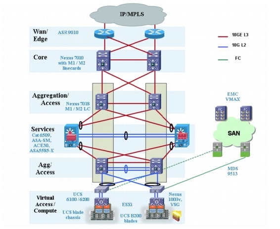
This multi-layered VMDC 2.2 architecture is comprised of Core, Aggregation, Services, and Access layers. This architecture allows for DC modules to be added as demand and load increases. It also provides the flexibility to create different logical topologies utilizing device virtualization, the insertion of service devices, and traditional Layer 3 (L3) and L2 network configurations. Figure 2-4 provides a logical representation of the VMDC 2.2 architecture, with the Services layer comprised of the Catalyst 6500 DSN, ACE30, and ASASM (or ASA 5585-X).
The VMDC 2.2 architecture forms the basis for the Cisco SP Cloud Smart Solutions Premier Offer for Cloud Ready Infrastructure kit.
Figure 2-4 provides a logical representation of the VMDC 2.2 architecture, with the Services layer comprised of the Catalyst 6500 DSN, ACE30, and ASASM (or ASA 5585-X).
Figure 2-4 VMDC 2.2 System Architecture
VMDC 2.3
The VMDC 2.3 architecture is based on VMDC 2.2 and also utilizes a Virtual Port-Channel (vPC) on the Nexus 7000 and Nexus 5000 switches to provide link and chassis redundancy capabilities. Downstream switches (Nexus 5500 or UCS 6100/6200 Fabric Interconnect) dual connect to a pair of Nexus 7000 aggregation switches, and the individual cross links across the chassis are bundled into a vPC link. The vPC across the chassis protects against any individual link or chassis failures and also provides L2 multi-pathing across the link members to provide higher aggregated bandwidths. In this design, the Nexus 7000 is utilized as the aggregation switch, while the Nexus 5000 and UCS 6100/6200 act as access switches. While the VMDC 2.3 system has been validated with F2 line cards on the Nexus 7004, any Nexus 7000 platform and any of M1, M2, F2 or F2e line cards can be used in this design.
This multi-layered VMDC 2.3 architecture is comprised of Aggregation (Nexus 7004) and Access (Nexus 5548 and UCS 6248) layers, along with services appliances (ACE 4710 and ASA 5500 appliances). VMDC 2.3 is an optimized version of VMDC 2.2 to meet a reduced cost and footprint, yet higher tenancy scale VMDC requirements from customers. In order to reduce the cost of the overall solution, and to increase tenant scalability (by reducing BGP and HSRP consumption on the Nexus 7000 Agg) the following changes have been made, from the VMDC 2.2 to VMDC 2.3 architectures:
•![]() Utilize ASR 1000 as WAN/PE layer, instead of ASR 9000
Utilize ASR 1000 as WAN/PE layer, instead of ASR 9000
•![]() Eliminate Nexus 7000 DC Core layer
Eliminate Nexus 7000 DC Core layer
•![]() Utilize Nexus 7004 as the Aggregation device Use cheaper F2 line cards on the N7004 (instead of M2 or M1) Eliminate Catalyst 6500 DSN and utilize ASA 5500 and ACE 4710 service appliances connecting directly to Nexus 7004 Agg
Utilize Nexus 7004 as the Aggregation device Use cheaper F2 line cards on the N7004 (instead of M2 or M1) Eliminate Catalyst 6500 DSN and utilize ASA 5500 and ACE 4710 service appliances connecting directly to Nexus 7004 Agg
•![]() Optimized tenancy models
Optimized tenancy models
•![]() New Copper network container
New Copper network container
•![]() ACE used in one-arm SLB mode (instead of two-arm mode)
ACE used in one-arm SLB mode (instead of two-arm mode)
The VMDC 2.3 architecture forms the basis for the Cisco SP Cloud Smart Solutions Standard Offer for Cloud Ready Infrastructure kit.
Figure 2-5 provides a logical representation of the VMDC 2.3 architecture, with the Services layer comprised of the ACE 4710, ASA 5585-X, and ASA 5555.
Figure 2-5 VMDC 2.3 System Architecture

VMDC 3.0
The VMDC 3.0 design introduces FabricPath into the VMDC system architecture. Instead of using a vPC, the VMDC 2.0 architecture utilizes FabricPath on the Nexus 7000 and Nexus 5000 switches to provide link and chassis redundancy. FabricPath uses Intermediate System to Intermediate System (IS-IS) as the underlying control plane for MAC learning, and also provides much higher link capacity utilization through 16x equal cost multi-pathing (ECMP). FabricPath provides a larger, flatter L2 domain, with the capability for "Any VLAN Anywhere" across the DC. FabricPath can be used to extend the server VLANs within the pod, or across pods in the DC. In this design, the Nexus 5000 (and/or Nexus 7000) switches are used as FabricPath Leaf (Access) nodes, while Nexus 7000 switches are used as FabricPath Spine (Aggregation) nodes in the FabricPath domain. F1 (or F2) line cards are used on the Nexus 7000 switches for FabricPath downstream L2 connectivity, while M1 (or M2) line cards are utilized on the Nexus 7000 for upstream L3 connectivity.
Cisco FabricPath provides the following benefits to the VMDC 3.0 solution:
•![]() Replaces Spanning Tree with a mature link state protocol (IS-IS)
Replaces Spanning Tree with a mature link state protocol (IS-IS)
•![]() Single control protocol used for unicast/multicast forwarding, and VLAN pruning
Single control protocol used for unicast/multicast forwarding, and VLAN pruning
•![]() Expansion of the L2 domain—Any VLAN Anywhere (within pod and across pods)
Expansion of the L2 domain—Any VLAN Anywhere (within pod and across pods)
•![]() Improved link capacity usage through 16-way ECMP
Improved link capacity usage through 16-way ECMP
•![]() Improved convergence time
Improved convergence time
•![]() Easy expansion—add additional access or spine nodes in plug-n-play manner
Easy expansion—add additional access or spine nodes in plug-n-play manner
Figure 2-6 provides a logical representation of the VMDC 3.0 typical DC architecture with FabricPath utilized within the pod, and the Services layer comprised of the ACE 4710 and ASA 5585 appliances (or Catalyst 6500 DSN, ACE30, and ASASM).
Figure 2-6 VMDC 3.0 System Architecture
 Feedback