Cisco Cloud Architecture for the Microsoft Cloud Platform: Backup as a Service Implementation Guide
Bias-Free Language
The documentation set for this product strives to use bias-free language. For the purposes of this documentation set, bias-free is defined as language that does not imply discrimination based on age, disability, gender, racial identity, ethnic identity, sexual orientation, socioeconomic status, and intersectionality. Exceptions may be present in the documentation due to language that is hardcoded in the user interfaces of the product software, language used based on RFP documentation, or language that is used by a referenced third-party product. Learn more about how Cisco is using Inclusive Language.
- Updated:
- May 13, 2015
Chapter: Implementation and Configuration
- Validation Environment
- Use Case 1 (In-Cloud BaaS): Implementation Details
Implementation and Configuration
This chapter covers the implementation and design details configured during the testing phase of this project. The testing process involved a number of functional, operational, and negative test cases applied to each use case. This chapter does not include explicit details, like those found in a configuration guide for deployment; instead guidance is given for deployment considerations and best practices, along with links to documentation for installation, configuration, and troubleshooting.
Validation Environment
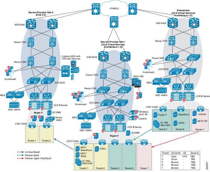
Figure 4-1 shows the scope of the lab environment used to cover all of the project’s use cases and deployment scenarios. This lab environment is a subset of the CCA-MCP full architecture.
The validation environment consisted of three sites. Two of these sites were built to represent Cloud Service Providers, Service Provider 1 (SP1) and 2 (SP2). The third site was built to represent the Enterprise-class tenants. Each of these sites was connected over an IP cloud. The following sections give details of the sites' architectures and their interconnectivity. The arrows in Figure 4-1 indicate the direction of traffic for the three use cases, as follows:
- In-Cloud BaaS— is represented by the blue arrow from SP1 to SP2. The protection for Tenants 1 and 2 uses local backup retention in the SP1 Media Agents with remote backup data sent to the Media Agents in SP2.
- Remote BaaS— is represented by the red arrow from Enterprise to SP1. The protection for Tenants 6 and 7 used local backup retention in the Enterprise Media Agents with remote backup data sent to the Media Agents in SP1.
- Remote BaaS without Local Retention— is represented by the green arrow from Enterprise to SP1. Without local retention the protection policy for Tenant 5 transmits all backup data the Media Agents in SP1.
CCA-MCP architecture provides a shared services network segment which is accessible by all tenant VMs. CCA-MCP Infrastructure Foundation Guide Shared Services Access configuration section provides the configuration details to setup shared services access. BaaS Commvault central infrastructure components are placed in this shared services network, so it becomes accessible for tenants.
Solution Components
Table 4-1 shows the components used during the validation testing. Refer to component information for the CCA-MCP Architecture 1.0.2 infrastructure.
SP1 Site Overview
The SP1 site was built to serve as the primary service provider data center in this solution architecture. It was integral in all of the use cases and replication scenarios.
IaaS Architecture
The data center infrastructure for the SP1 site is based on CCA-MCP Architecture 1.0 The CCA-MCP is a fully tested reference design that can be leveraged by enterprises and service providers to deploy an infrastructure that is efficient, secure, resilient, agile, simple, and scalable.
Cisco UCS
The SP1 site used both UCS B-Series and C-Series compute hardware. The B-Series were used to deploy the Microsoft Hyper-V environment, including the infrastructure and production Hyper-V hosts. The C-Series were used to deploy the Commvault CommServer, MediaAgents, and Reporting Server.
B-Series
The UCS B200 M3 servers were managed by the Cisco UCS Manager (UCSM) running release 2.2(1b). Two Service Profile templates were created on the UCSM, one for the infrastructure (management) hosts and one for the production tenant traffic) hosts. Both templates required certain BIOS settings to be explicitly configured as required for Hyper-V installed on an Intel-based server. The Execute Disabled Bit and the Virtualization technology (VT) settings were enabled in a BIOS policy that was referenced in the Service Profile templates. In addition to the BIOS settings, the Adapter Policy was set to “Windows”, and Fabric Failover was enabled.
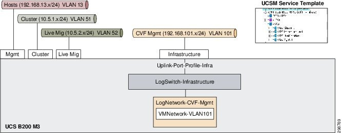
For the infrastructure Hyper-V host, three of the four configured vNICs were used by the host to enable connectivity to the host management, cluster, and live migration VLANs. None of the virtual machines on the Hyper-V host required connectivity to these VLANs. On the UCSM, these VLANs were configured to be the native VLANs (untagged) on these vNICS and IP addresses were configured on all of these interfaces via the Windows OS on the Hyper-V host. The infrastructure management VLAN101 was used by multiple virtual machines and was therefore connected to a logical switch through the Infrastructure vNIC on the B200 M3. This allowed infrastructure management servers, such as Microsoft System Center Virtual Machine Manager (SCVMM) and Active Directory, to connect into the management VLAN.
Figure 4-2 shows the Service Provider 1 with the Hyper-V host infrastructure.
Figure 4-2 SP Site 1 Using Native Hyper-V Networking for Infrastructure Hyper-V Hosts
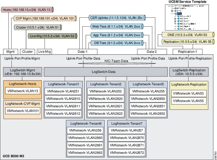
For the production Hyper-V hosts, native Hyper-V networking was originally configured and then later migrated to Cisco Nexus 1000V for Hyper-V. For the native Hyper-V networking configuration, six vNICS were configured in the UCSM Service Profile template.
The management vNIC on the production hosts carried two VLANs which were used by virtual machines on the hosts. A logical switch was configured to allow connectivity for the virtual machines to VLAN13 and VLAN101. The Hyper- V hosts required an interface in the host management VLAN13, so a virtual Ethernet interface was created in the Hyper-V logical switch via the Hyper-V Manager on each of the Hyper-V hosts.
Two of the six configured vNICs were used by the host to enable connectivity to the cluster and live migration VLANs. None of the virtual machines on the Hyper-V hosts required connectivity to these VLANs. On the UCSM, these VLANs were configured to be the native VLANs (untagged) on these vNICS and IP addresses were configured on these interfaces via the Windows OS on the Hyper-V hosts.
For the tenant traffic on the production Hyper-V hosts, a logical switch was created with two uplinks teamed together at the Microsoft OS level and configured for fabric failover at the Fabric Interconnect level. All twenty tenant VLANs were configured to be carried on these vNICs on the UCSM with tagging enabled. For each tenant, a logical network was configured and associated with only the VLANs that are used by the tenant.
The sixth vNIC on the Hyper-V host was used for Commvault replication and DMZ traffic. A Hyper-V logical switch was configured to allow virtual machines the needed access to the replication or DMZ VLAN. Only the DMZ Web Proxy server had an interface in the DMZ, with all access to and from it, restricted by the ASA firewall. Alternatively, the VLANs were included in the tenant uplinks.
Figure 4-3 shows Service Provider 1 using the Hyper-V host for production.
Figure 4-3 SP Site 1 Using Native Hyper-V Networking for Production Hyper-V Hosts
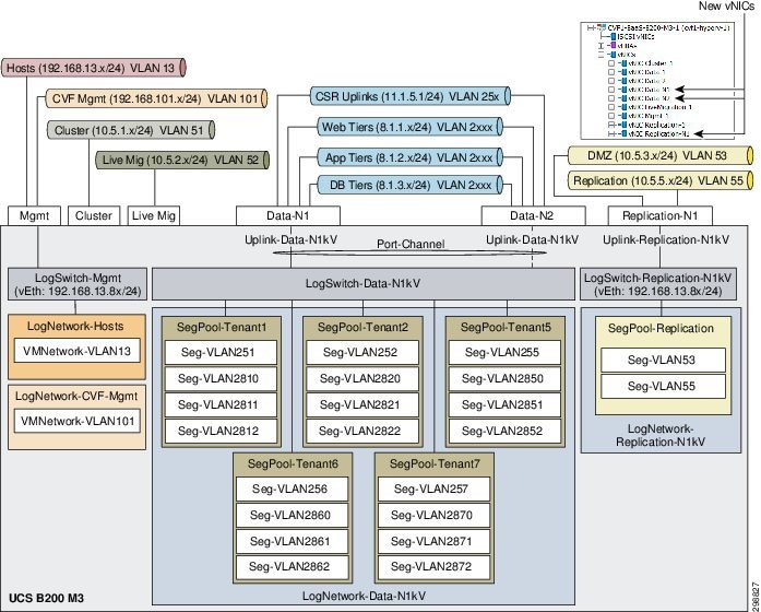
CCA-MCP architecture utilizes native Hyper-V networking configuration for the production (tenant) traffic rather than Nexus 1000v, however, this lab configuration was implemented with Cisco Nexus 1000V. The new logical networks, switches, and VLANs from the Nexus 1000V were associated with the new vNICs and, once operational, the interfaces on the virtual machines were changed in the SCVMM. The management VLANs remained on the native Hyper-V networking. The configuration details of the Nexus 1000V will be discuss in the Cisco Nexus 1000V section below.
Figure 4-4 shows the Nexus 1000V logical network hierarchy.
Figure 4-4 Nexus 1000V Logical Network Hierarchy
Two vHBA interfaces were configured in the Service Profile template for the production Hyper-V hosts to allow FibreChannel access to remote storage. Three LUNs were made available to the Hyper-V hosts, 1GB for the cluster quorum drive, 200GB for the first shared cluster volume, and a 2TB for the second shared cluster volume. There were multiple paths between the vHBAs and the target LUNs, so MPIO with the appropriate drivers for the storage must be configured in Windows 2012 R2. If MPIO is not enabled, a target LUN will appear multiple times in Disk Management in the Windows OS.
C-Series
The UCS C240 M3 servers were tested running version 2.0(3d), and later upgraded to 2.0(3i). The C240 M3 is managed by the UCSM or managed locally in standalone mode. Only the latter method supports multiple RAID configurations, which was required on the Commvault MediaAgent servers. Therefore, all of the C240 M3 were configured for standalone mode.
Figure 4-5 shows the physical drives that were used on the C240 M3 for the MediaAgent. There were five physical drives available, three 380 GB SSD and two 285 GB HDD.
Figure 4-5 Cisco UCS C240 M3 Physical Drives
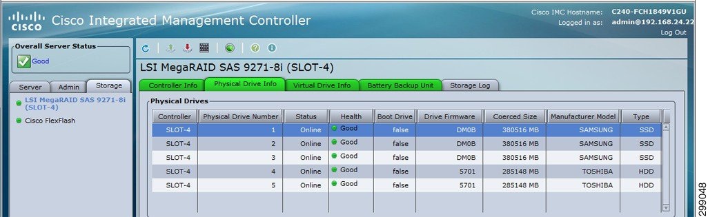
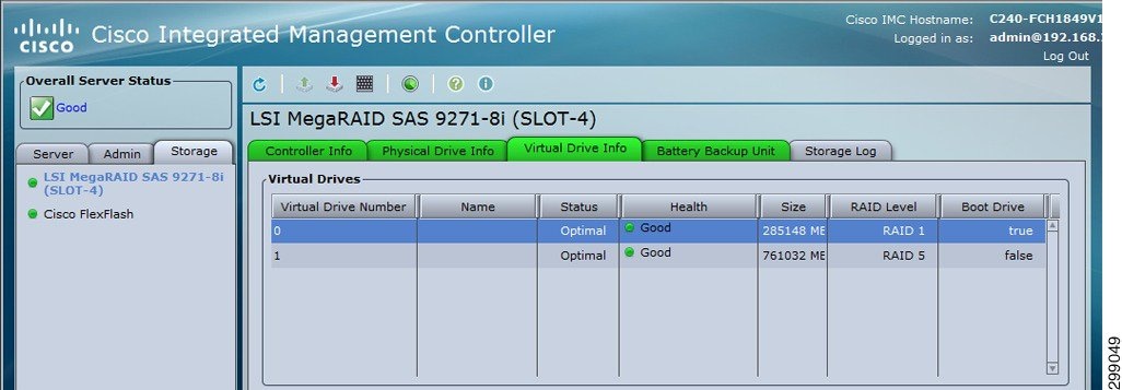
The HDDs were configured for RAID1 and used for the Windows 2012 R2 operating system and MediaAgent software. The SSDs were configured for RAID5 and used for backup data. Figure 4-6 shows the M3 RAID configurations.
Figure 4-6 Cisco UCS C240 M3 RAID Configurations
As for the network connections, the Commvault components were connected to the infrastructure management via the LOM (LAN on Motherboard) and connected to the replication network via the UCS VIC1225. A virtual Ethernet (vNIC) interface was configured and connected to the Nexus 5548 access layer switch. For the SP1 site, the vNIC interface and the Nexus switchport were configured as access switchports in VLAN55. Alternatively, the vNIC and Nexus switchport could be configured as trunk interfaces with a native VLAN configured for VLAN55. The latter approach was used in the SP2 site.

Note![]() During validation testing, an issue was discovered that impacted the C240 servers from receiving broadcast packets. The issue was isolated to the VIC 1225 network driver in release 2.0(3d) (CSCur44975) and was resolved in the VIC driver in release 2.0(3i).
During validation testing, an issue was discovered that impacted the C240 servers from receiving broadcast packets. The issue was isolated to the VIC 1225 network driver in release 2.0(3d) (CSCur44975) and was resolved in the VIC driver in release 2.0(3i).
Microsoft Hyper-V
The Hyper-V cluster in the SP1 site was deployed on three B200 M3 blades to host the tenant and Commvault virtual machines. An additional blade was deployed to run Hyper-V in a non-clustered environment to host the infrastructure virtual machines. The following components were used:
- Windows Server 2012 R2—Datacenter version used for Hyper-V hosts, both Datacenter and Standard versions used for virtual machines.
- Active Directory Server 2012—Used for authentication and DNS for the cluster.
- SQL Server 2012 R2—Used for the relational database.
- System Center Virtual Machine Manager 2012 R2—Used to manage the infrastructure and virtual machines of the Hyper-V cluster.
- Failover Cluster Manager—Used to proof, create, and monitor the Hyper-V cluster.
- Hyper-V Server 2012 R2—Native hypervisor that enables virtualization of the x86-64 architecture. Installed as a role inside of Windows 2012 R2.
Note![]() Configuration and management of the Hyper-V environment can be challenging and the recommendation is to manage from the top down using SCVMM first, Failover Cluster Manager second, and Hyper-V Manager last.
Configuration and management of the Hyper-V environment can be challenging and the recommendation is to manage from the top down using SCVMM first, Failover Cluster Manager second, and Hyper-V Manager last.
Creating the Hyper-V Cluster
Before the Hyper-V cluster was created, the following prerequisites were satisfied.
- A Windows Active Directory and DNS need to be available to the hosts.
- The Cisco UCS blades need to have Windows 2012 R2 Datacenter installed with Cisco VIC network and storage drivers installed. Without the VIC drivers, the OS will not be able to recognize the network and storage interfaces.
- If multiple data paths exist between the server and remote storage, the Multipath I/O feature is installed from Windows Server Manager and the MPIO driver for the storage vender is manually installed, if not included in Windows already.
Refer to Cisco UCS B-Series Blade Servers Windows Installation Guide for installing Windows on the Cisco UCS B-Series servers.
Once all the software and drivers were installed, basic configuration of the Windows OS was performed, including time adjustments, Windows updates, adding to local domain, firewalls, and so on. Multiple NICs were configured on the host; for example, the configuration interfaces in management were configured as were the replication VLANs (this is a minimal requirement).
From the Windows Server Manager interface, the Hyper-V and Failover Clustering features were installed on all servers that were hosts in the cluster. With the new features installed, Windows Update was used to load the available updates.
Storage configuration is dependent on the deployment environment, but there should be shared storage available to all hosts via SCSI, FibreChannel, etc. A quorum (or witness) disk can be used for the quorum configuration, which is a small LUN formatted for NTFS or ReFS. Large NTFS LUNs can be configured as Cluster Shared Volumes (CSVs) to store virtual machines configuration files and virtual hard drives. During the verification testing of this solution, several LUNs were created on a remote storage system and made available to the Hyper-V hosts. This included a small volume (1 GB) that was used by the cluster as a quorum drive, and two large LUNs (200GB, 2TB) that were used to store virtual machine files and virtual hard drives.
Refer to Failover Clustering Hardware Requirements and Storage Options for hardware requirement and storage options for failover cluster.
On one of the servers, the Failover Cluster Manager was opened and the Create Cluster Wizard was used to verify the servers. The wizard ran through multiple suites of tests to make sure that all networking, storage, and other requirements were met before the cluster was actually created. If any issues were discovered by the wizard, the issues were fixed, and the wizard was rerun. There were a large number of online resources available to help resolve any of the many issues that may arise during the validation.
Note![]() There was one issue that was observed for which the fix was difficult to find. A shared disk used for the cluster (originally formatted for NTFS) can show up as a RAW format on some hosts. There was a persistent reservation on the disk and if formatting is attempted, it may display an error “the requested resource is in use”. Refer to Microsoft Technet for details on command Clear-ClusterDiskReservation -Disk <#> to resolve this issue.
There was one issue that was observed for which the fix was difficult to find. A shared disk used for the cluster (originally formatted for NTFS) can show up as a RAW format on some hosts. There was a persistent reservation on the disk and if formatting is attempted, it may display an error “the requested resource is in use”. Refer to Microsoft Technet for details on command Clear-ClusterDiskReservation -Disk <#> to resolve this issue.
When the validation passed, the cluster was created. A cluster name and virtual IP address were configured and registered in the local Active Directory and DNS server. By default, all available storage was added to the cluster with the smallest shared volume used as the quorum disk.
Configuration changes and monitoring of the failover cluster was done from the Failover Cluster Manager on any of the hosts in the cluster.
Figure 4-7 shows the Failover Cluster Manager window.
Figure 4-7 Failover Cluster Manager

System Center Virtual Machine Manager
SCVMM is the central management interface for the Hyper-V virtualized data center. It can be used to configure and manage the Hyper-V hosts, networking resources, and storage resources to deploy virtual machines and services in a private cloud. SCVMM consists of the following components:
- VMM Management Server—Server that runs the VMM service, which processes commands to control the VMM database, library server, and hosts.
- VMM Database—Microsoft SQL database used to store configuration information (for example, virtual machines and service templates).
- VMM Console—The user interface into the VMM server.
- VMM Library—The library server hosts shared folders that are used as a repository for virtual hard disks, ISOs, templates, profiles, etc.).
- VMM Command Shell—Windows PowerShell with VMM cmdlets.
- VMM Self-Service Portal—Optional website to allow restricted access to cloud resources.
SCVMM can be deployed on a physical server or as a virtual machine. A SCVMM virtual machine deployed in a Hyper-V cluster would provide high availability and it could be deployed inside a cluster that it will manage. Once deployed, new Hyper-V hosts and clusters can easily be added to the SCVMM with all host, storage, network, and VM information for the host and/or cluster available via the SCVMM.
Native Hyper-V Networking
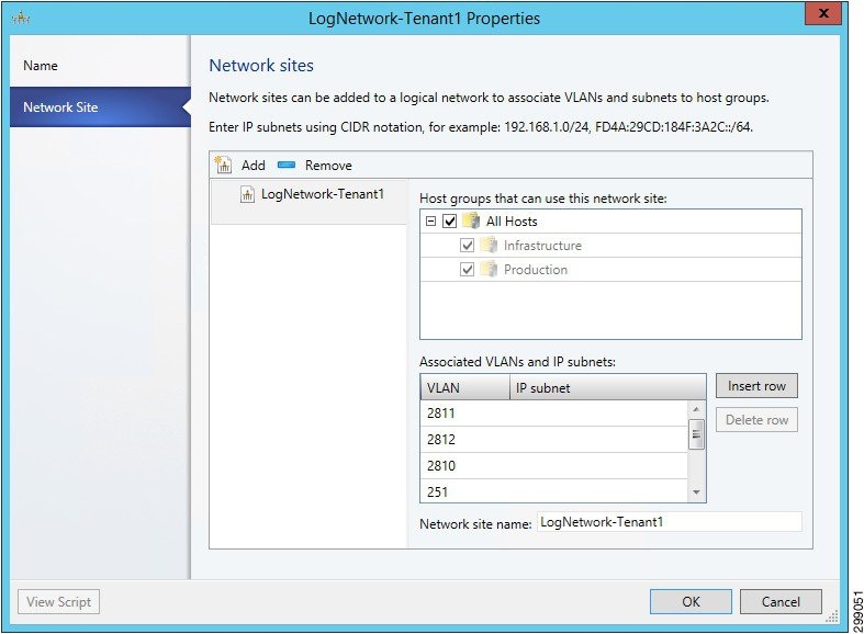
In SCVMM, logical networks were created to associate multiple VLANs into groups. For example, in the verification testing of the solution, a logical network was created for the management VLANs, each group of tenant VLANs, and the Commvault replication VLAN. Figure 4-8 shows the logical network for Tenant 1, which associates the CSR 1000V uplink (VLAN 251) with the three tiers for web, application, and database (VLAN 2810-2812).
Figure 4-8 SCVMM Logical Network Sample
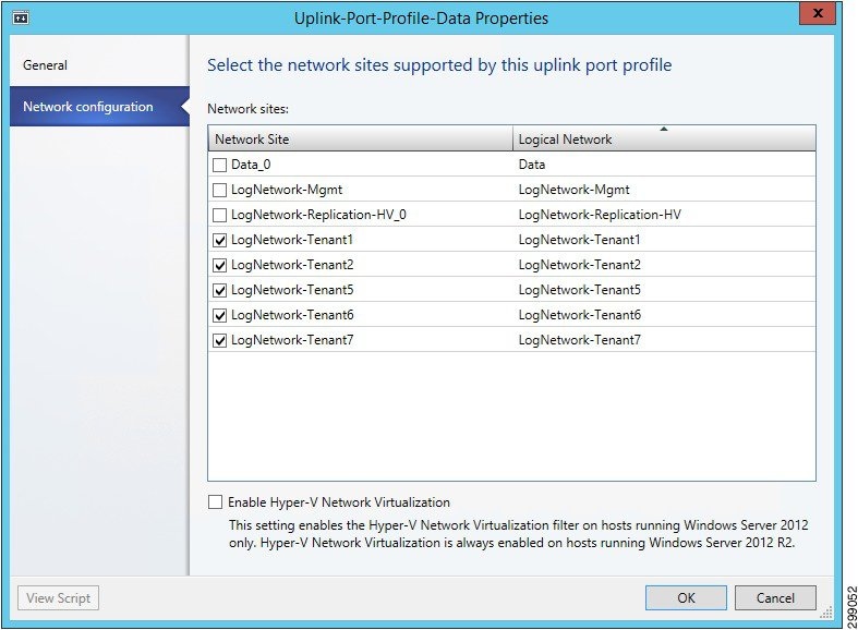
Once the logical networks were configured, uplink port profiles were created and associated with the logical networks. The uplink port profile was configured to allow select VLANs to be received and forwarded across an uplink. For example, in the verification testing of the solution, uplink port profiles were created for the management uplink, the data uplink for tenant traffic, and the replication uplink for the Commvault traffic. Figure 4-9 shows the port profile to the tenant data traffic, which includes all tenant logical networks.
Figure 4-9 SCVMM Uplink Port Profile Sample
Next, logical switches were created on the Hyper-V hosts to provide an access layer for the virtual machines. The logical switch must be associated with the correct uplink port profile, which in turn associates the correct logical networks. For example, in the verification testing of the solution, three logical switches were created, one for management, one for all tenant data traffic, and one for Commvault replication traffic. In Figure 4-10, the logical switch for the tenant data traffic was associated with the uplink port profile for tenant traffic.
Figure 4-10 SCVMM Associating Logical Switch with Uplink Sample
Next, the virtual machine networks were created with references to the logical network and VLAN. The VM Network was associated with the virtual machines to provide the desired access to the data center network (Figure 4-11).
Figure 4-11 SCVMM Virtual Machine Network Sample
Now that the virtual networking is configured, the logical switches can be associated with the Hyper-V hosts. Figure 4-12 shows an example of the SCVMM host virtual switch.
Figure 4-12 SCVMM Host Virtual Switch Sample
To provide network access to a VM, the VM properties were configured from the SCVMM. Under Hardware Configuration, a new network adapter created or an existing one was selected and the appropriate VM network was specified. The VLAN ID and Virtual switch also need to be selected from the dropdown menus. Figure 4-13 shows the SP1 Tenant1 CSR 1000V properties.
Figure 4-13 SCVMM Virtual Machine Network Properties
Refer to Cisco Unified Computing System with Microsoft Hyper-V Recommended Practices and Microsoft Technet Library - System Center Virtual Machine Manager 2012 for details on deploying Microsoft Hyper-V on the Cisco Unified Computing System.
Resource Reservation for Commvault VSA
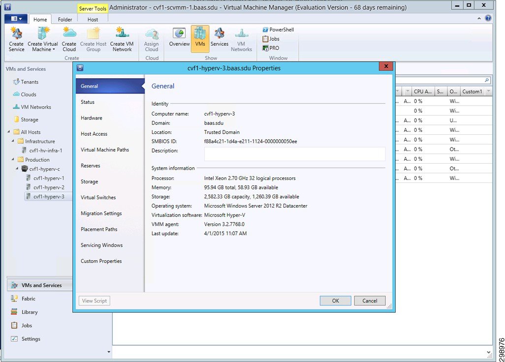
For a Hyper-V deployment the Virtual Server Agent is installed directly on the host blade. This does not need to be installed on all blades in a cluster, but at a minimum there should be two for redundancy. The VSA monitors traffic from all VMs hosted in the cluster and performs backup and restore operations in conjunction with the Media Agent and CommServ Manager servers. Since the agent is loaded directly on the host, it can compete for resources with the VMs hosted on that blade. There are default resource reservations for a Hyper-V host, but they are minimal and not sufficient to ensure adequate operation.
The B200 M3 blades have 2 CPUs, a total of 16 cores and 32 threads. These resources are displayed as 32 logical processors under the Hyper-V Host>Properties>General tab.
Figure 4-14 Hyper-V Host System Information
Under the Reserves window you need to check the box to ‘Override host reserve settings’. In this solution, the following resources were reserved for hosts cvf1-hyperv-2 and cvf1-hyperv-3 in Cloud Service Provider SP1 (Figure 4-15).
Figure 4-15 Hyper-V VSA Resource Reservations
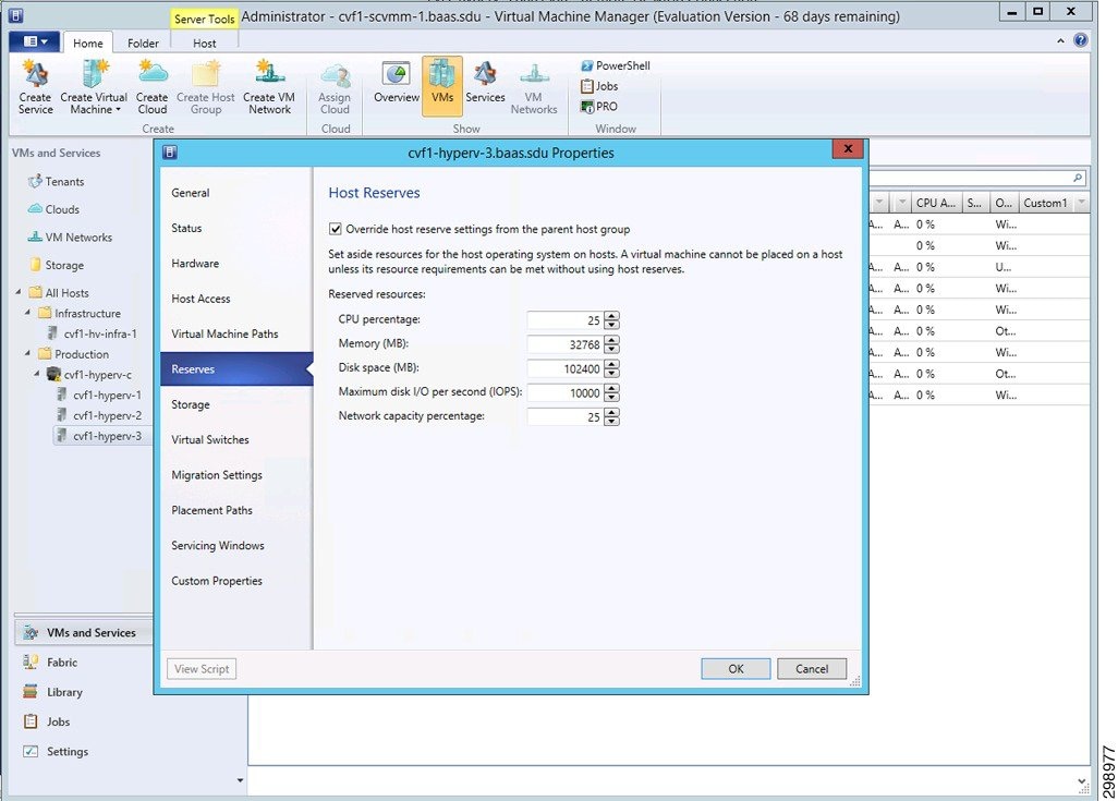
Refer to Commvault documentation for more information regarding VSA requirements.
Cisco ASA 5585 Firewall
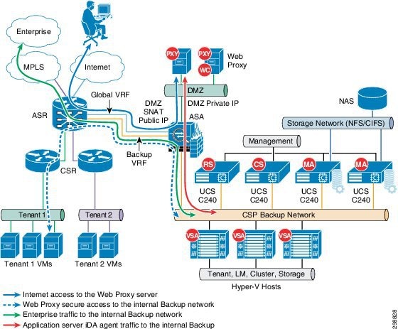
In this system solution, the ASA 5585 is used as a perimeter firewall to provide access to the Commvault Web Proxy Server located in a DMZ and restricted access to the internal backup network in Cloud Services Provider SP1. The ASA is configured in a routed, multi-context mode with active/backup failover configured.
The DMZ Commvault web proxy server is used to allow customers Self Service Backup and Recovery Services without direct access to the inside backup network. The ASA is configured to allow access from outside sources to the web proxy server through a restricted set of ports. From the DMZ only Web Proxy originated traffic is allowed to access the internal Commvault components on the inside network. The DMZ subnet is configured with private IP addressing, so static NAT is configured to provide access to outside sources.
Communication is required between the Commvault components from different CSP locations connecting to the inside backup network behind the ASA firewall. Traffic originating from these locations over MPLS, or other methods, are allowed bi-directional communication through the ASA to the internal Commvault components.
The replication and Commvault management traffic routes to the inside backup network in CSP1 through the ASA from a backup VRF created on the ASR 9000. The ASR is configured using Import/Export route descriptors (RD) to learn these routes, along with static routes to and from the ASA. Tenant VRF specific routes are also shared for instances of when a specific server (SQL, etc.) is selected for backup and needs to communicate directly to the Commvault components on the inside network. An alternate solution could have the server communicate with the DMZ Proxy server instead of directly to the internal backup network.
Figure 4-16 shows these traffic streams.
- Internet User is not allowed access to the Commvault components, so it uses the DMZ Web Proxy to manage Backup and Restore operations.
- The DMZ Web Proxy server acting on behalf of the Internet users is allowed to communicate with the internal Commvault components, providing a layer of separation and security.
- Enterprise traffic both management and data replication needs bi-directional communication with the internal Commvault components. This traffic routes over a L3VPN/MPLS cloud, through the Backup VRF on the WAN router to reach the ASA Firewall, which has a local interface to the internal backup network.
- For administrators in Tenant 1 or for application servers running the iDA agent, these communicate with the internal backup network through the Backup VRF, which includes the backup network and private tenant routes.
If including the private tenant routes is not desirable in the Backup VRF, communication can be achieved through the same path, but through the DMZ Web Proxy. This flow is not depicted in the illustration.
Figure 4-16 Traffic Flows Through ASA Firewall
Cisco Cloud Services Router (CSR) 1000V
Beginning with Cisco IOS XE Release 3.12S, the Cisco CSR 1000V supports installation on the Microsoft Hyper-V hypervisor using Windows Server 2012 R2. The Cisco CSR 1000V installation on Microsoft Hyper-V requires the manual creation of a VM in Hyper-V and then installing the CSR software using a vDVD mapped to the CSR ISO image file. The amount of resources required for the CSR depends on the licensed feature set and throughput requirements. For the validation testing, five virtual interfaces were configured, one for management, one for the uplink in the access layer, and three for the tenant workloads (web tier, app tier, and database tier).
A separate CSR 1000V instance was deployed for each of the four tenants in the SP1 site that use Hyper-V or VMware ESXi hypervisors. The CSR 1000V did not support the OpenStack environment. The CSR 1000V was configured as the gateway for each of the VLANs used in the tenant workloads. This included the web, application, and database VLANs for each tenant. Since Layer 3 connectivity was used between the tenant CSRs at each site, unique IP subnets were configured to enable proper routing between sites. The CSRs used BGP routing to learn IP subnets connected to the remote site’s CSR.
Remote BaaS enterprise tenants (Tenants 5 and 7) used an IPsec tunnel between the CSR 1000V in the SP1 site and another tenant-specific CSR 1000V at the Enterprise site. The tunnel provided secure communications between the workload VLANs at each site. For the In Cloud BaaS tenants (Tenants 1-2), an IPsec tunnel was not configured since the network path between the sites was considered secure.
When the Cisco CSR 1000V is installed on a Microsoft Hyper-V cluster, the interface numbers can change after a Hyper-V host failover event to a new host server or live migration. In both cases, the condition is not seen until after a reboot. The following steps can be taken to mitigate this issue:
1.![]() Prior to executing a live migration enter the clear platform software vnic-if nvtable command.
Prior to executing a live migration enter the clear platform software vnic-if nvtable command.
2.![]() The command can also be successful if executed after the failover, but only before the config is saved or the VM restarted.
The command can also be successful if executed after the failover, but only before the config is saved or the VM restarted.
3.![]() Configuring static MAC addresses for the network interfaces.
Configuring static MAC addresses for the network interfaces.
In the event that the interfaces have been renumbered and the IP addressing is removed, the following steps can be used to recover.
1.![]() Execute clear platform software vnic-if nvtable command.
Execute clear platform software vnic-if nvtable command.
2.![]() Copy saved config to startup config.
Copy saved config to startup config.
Refer to the following links for details of the Cisco CSR 1000V Series Cloud Services Router:
Cisco Nexus 1000V
Cisco Nexus 1000V Series switches provide a comprehensive and extensible architectural platform for virtual machine and cloud networking. These switches are designed to accelerate server virtualization and multitenant cloud deployments in a secure and operationally transparent manner.
In this solution, the Nexus 1000V is deployed as a distributed virtual switch running version 5.2(1)SM3(1.1) and integrates with Microsoft SCVMM 2012 R2 to allow deployment of virtual machines and to manage virtual networking.
This section is a high-level overview of the steps executed to install and integrate the Nexus 1000V into the test topology. The overview is based on the steps used in this validation project and are not meant to be a complete set of steps for installation.
Refer to Cisco Nexus 1000V Install and Upgrade Guide for installation details.
To reduce complexity in CCA-MCP architecture, Nexus 1000V was replaced with the native Hyper-V virtual switch later in the design. However, this BaaS Commvault lab testing stayed with the N1kv component.
Installation Files and Template
When installing the SCVMM components, the referenced filename for the MSI file is incorrect for this release. For this step, execute the Nexus1000V-NetworkServiceProvider-5.2.1.SM3.1.1.0.msi file from the <zip package>\VMM directory on the SCVMM server.
The VEM software is a MSI file that needs to be copied (do not execute) into the following location on the SCVMM server: C:\ProgramData\Switch Extension Drivers. By default, the directory C:\ProgramData is hidden.
VSM Installation
In the Configured Hardware window you can either leave the Availability to Normal or set it to High. In this deployment active and standby VSMs were configured using Nexus 1000V high availability on a standalone Hyper-V host. Preferably two hosts should be used when configured in this manner to prevent a single point of failure.
If the VSMs are deployed in a Hyper-V cluster the availability mode should be set to High, which allows Hyper-V to spawn a replacement VM on another host if the original one should fail. It is important that both VSM VMs do not reside on the same Hyper-V host, so that service can be restored much faster than through the Hyper-V HA feature. To ensure this separation use an anti-affinity class. Some important items are:
- The VSM template installs three network adapters. In the Select Networks window choose the management network that is shared between the hosts and VSM for all three interfaces.
- In the Add Properties window, select Always turn on the virtual machine, then configure Delay start up 30 seconds, Turn off virtual machine, and Exclude virtual machine from optimization actions.
- After the VSM boots and the initial configuration applied you should unmap the VSM.iso image from the Virtual DVD drive.
After completing these steps, you are prompted to log into the VSM. Access the VSM via SSH using the IP address configured in the VSM installation section. The following objects need to be created on the VSM:
- Logical Network
- Network Segment Pool
- IP Pool Template
- Network Segment
- Virtual Ethernet Port Profile
- Ethernet Port Profile
- Network Uplink
Logical Network —A single logical network could be configured, but in this solution two were created; one for the Commvault replication traffic and the other for tenant data traffic. This is imported into the SCVMM under Fabric>Logical Networks.
Network Segment Pool – Is a container for all of the Network Segments that are created for each VLAN. The Network Segments link to this pool and it links them to the appropriate Logical Network.
IP Pool Template —Create an IP address pool for each VLAN. These are the IP addresses that could be dynamically assigned to your VMs, if you are using the SCVMM for automation. Though we did not dynamically assign these IP addresses, values must be configured; otherwise the Nexus 1000V will not integrate properly with the SCVMM. If you are using overlapping IP address space for private tenant networks, the same IP Pool Template can be imported into multiple Network Segments.
Network Segment —A Network Segment needs to be created for each VLAN and made a member of the appropriate Network Segment Pool. The ipsubnet command must be configured first and match the network configured in the imported IP Pool Template.
Virtual Ethernet Port Profile —To apply policies to the VMs, create a port-profile for them. This port-profile is not used for access, but as a collection of policies. Apply service policies for QoS or to bind a service, such as a VSG. Examples are displayed below, but were not used in verification testing.
Ethernet Port Profile —An Ethernet port profile is created to apply any needed policies to the Network Uplink. This profile needs to be imported into the NSM Network Uplink configuration shown in the next step. If none is created a default policy is automatically imported into the Network Uplink. Below is an example of an uplink port profile with egress QoS marking applied. In verification testing, the default port profile was used.
Network Uplink —This is used as the uplink from the host when the virtual switch is created. Each uplink is configured to allow certain segment pools. The allow network segment pool command tells SVCMM that these segments are allowed out this uplink. This is needed for the host to see the segments. If an Ethernet Port Profile is created, then it needs to be imported here; otherwise it uses the default profile.
After the Nexus 1000V configuration is complete a communication channel needs to be configured to integrate the switch into the SCVMM. Follow the steps in the Connecting SCVMM to VSM section of the Cisco Nexus 1000V Install and Upgrade Guide.
The following section discusses steps necessary to apply the Nexus 1000V configuration to the Hyper-V hosts and VMs.
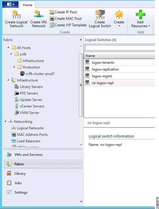
- Create Logical Switch (Figure 4-17)
- Create VM Networks
- Add Virtual Switch to Hosts
- Assign VM Networks to VM network interfaces
On the SCVMM, under Fabric>Networking>Logical Switches create a Logical Switch.
Figure 4-17 Logical Switch Creation
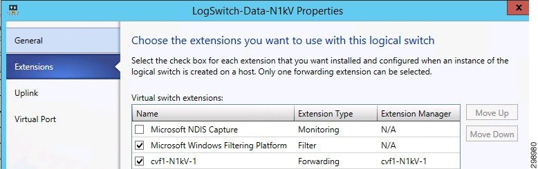
In the Extensions window leave the Microsoft Windows Filtering Platform checked and select the Nexus 1000V Forwarding extension (Figure 4-18).
Figure 4-18 Logical Switch Extensions
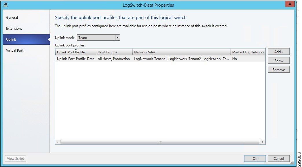
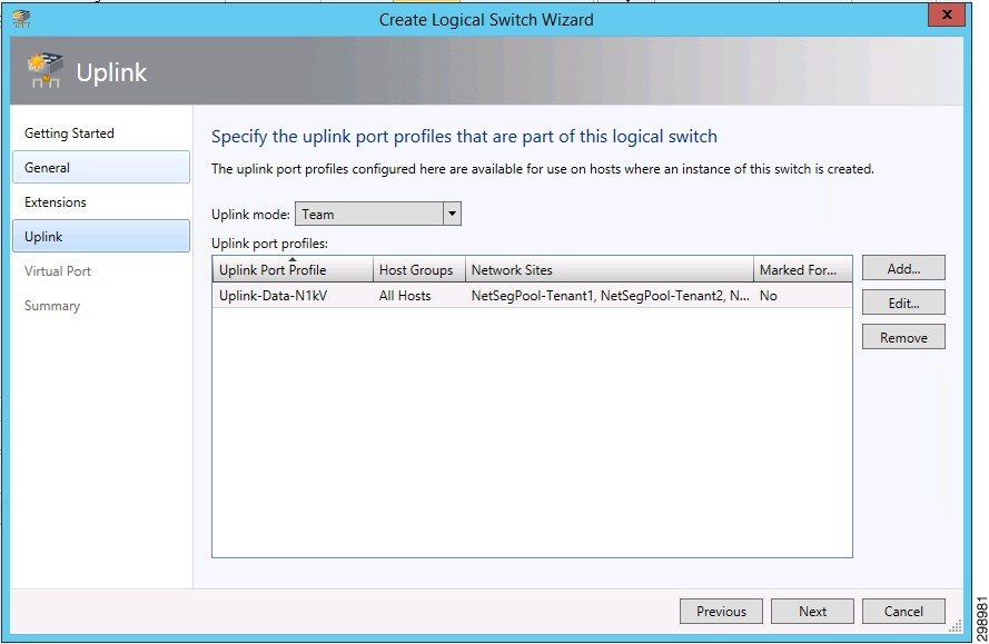
In the Uplink window, under the Uplink port profiles section, add the NSM network uplink that was configured on the Nexus 1000V. All of the network segment pools that were allowed will show up under the Network Sites column.
The vNIC interfaces from the UCS host will be linked to the Logical Switch when a new Virtual Switch is configured at the Hyper-V host level.
Note![]() The Uplink mode must be set to Team even if only one interface is configured.
The Uplink mode must be set to Team even if only one interface is configured.
Figure 4-19 Logical Switch Extensions
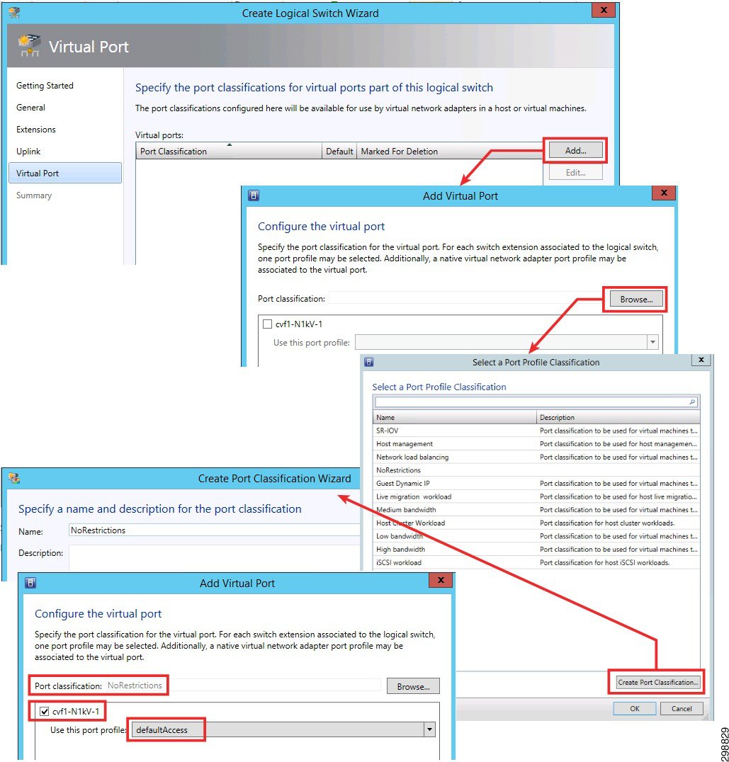
In the Virtual Port window perform the following:
Note![]() Steps 1- 4 are represented by arrows and the remaining steps use highlighted boxes.
Steps 1- 4 are represented by arrows and the remaining steps use highlighted boxes.
1.![]() Click on Add to include a virtual port.
Click on Add to include a virtual port.
2.![]() Click on Browse to open the Port Profile Classification window.
Click on Browse to open the Port Profile Classification window.
3.![]() Click on Create Port Classification to create one.
Click on Create Port Classification to create one.
4.![]() Type in a name and click Ok.
Type in a name and click Ok.
5.![]() In the Add Virtual Port window browse and select the port classification that was created.
In the Add Virtual Port window browse and select the port classification that was created.
6.![]() Select the Nexus 1000V that was created.
Select the Nexus 1000V that was created.
7.![]() Select a port profile (vEthernet port profile) if one was created. If not, a defaultAccess profile will exist.
Select a port profile (vEthernet port profile) if one was created. If not, a defaultAccess profile will exist.
8.![]() Hit Ok and Finish to complete the Logical Switch configuration.
Hit Ok and Finish to complete the Logical Switch configuration.
Figure 4-20 Logical Switch Creation
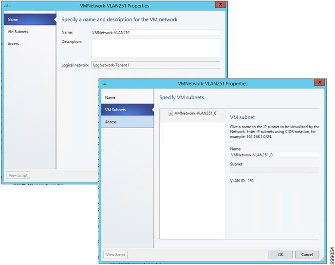
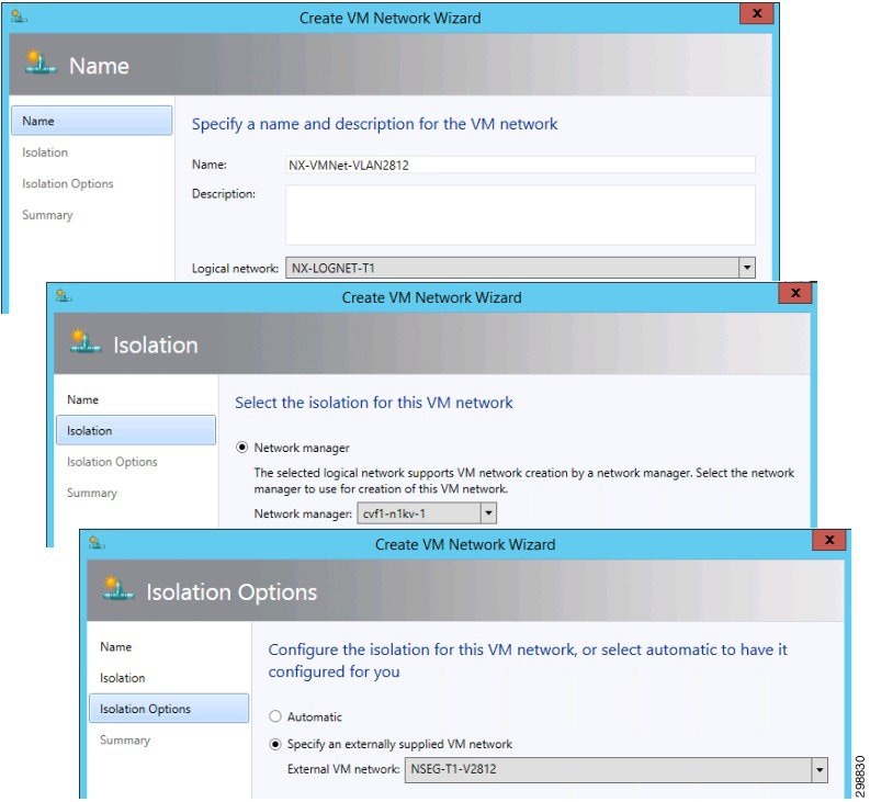
VM Networks now need to be configured. These are created under VMs and Services>VM Networks>Create VM Network.
1.![]() Name the network and select the Logical Network that was configured through the Nexus 1000V CLI.
Name the network and select the Logical Network that was configured through the Nexus 1000V CLI.
2.![]() Select the Nexus 1000V instance that was created.
Select the Nexus 1000V instance that was created.
3.![]() For Isolation Options click on Specify an Externally Supplied VM Network and use the pulldown arrow to select a Network Segment that was created through the Nexus 1000V CLI. Only the segments that are assigned to the Logical Network in Step 1 are available and as they are chosen, they are removed from the selection list.
For Isolation Options click on Specify an Externally Supplied VM Network and use the pulldown arrow to select a Network Segment that was created through the Nexus 1000V CLI. Only the segments that are assigned to the Logical Network in Step 1 are available and as they are chosen, they are removed from the selection list.
Figure 4-21 VM Network Creation
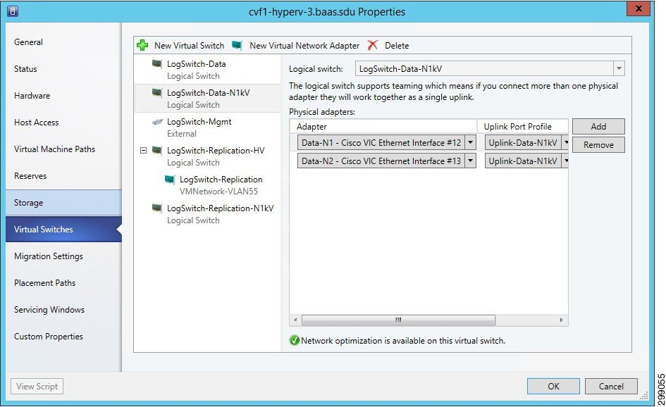
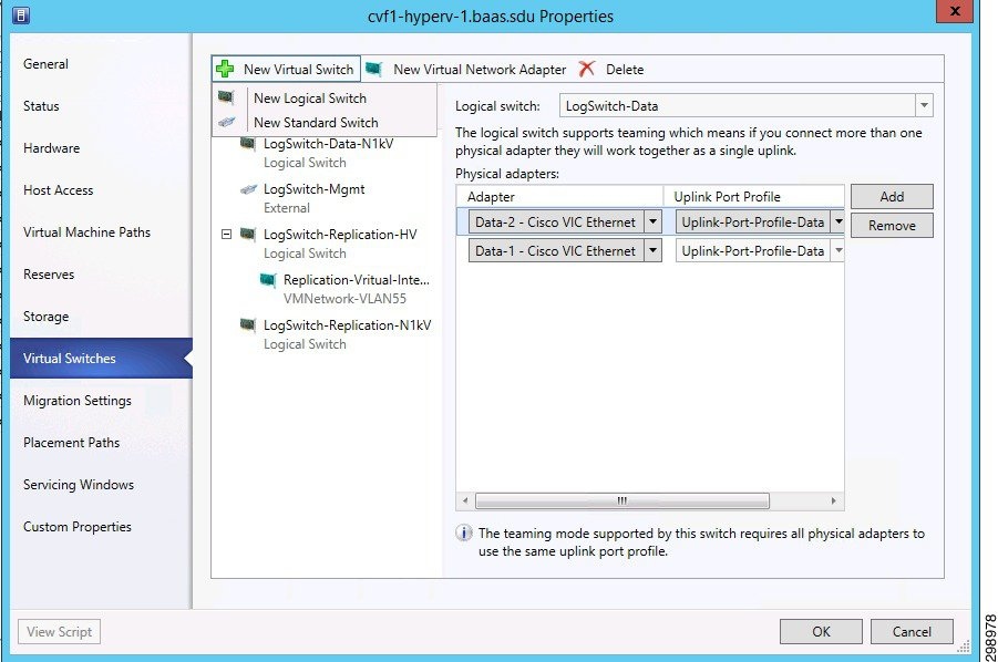
A new virtual switch needs to be added to each host in the cluster. This connects the Nexus 1000V to the host blade by installing the VEM software. From the VMs and Services>All Hosts, right click on the Host>Properties>Virtual Switches and then proceed with the following steps.
1.![]() Click on New Virtual Switch>New Logical Switch.
Click on New Virtual Switch>New Logical Switch.
2.![]() From the pulldown arrow select the Logical switch that was created in prior steps.
From the pulldown arrow select the Logical switch that was created in prior steps.
3.![]() Click on Add to include all of the vNICs that are configured from the UCS for this host blade and Virtual switch to use. For the Data Uplink there are two interfaces.
Click on Add to include all of the vNICs that are configured from the UCS for this host blade and Virtual switch to use. For the Data Uplink there are two interfaces.
4.![]() Select the Uplink Port Profile from the pulldown. Only the NSM Network Uplinks that were created through the Nexus 1000V CLI will be available.
Select the Uplink Port Profile from the pulldown. Only the NSM Network Uplinks that were created through the Nexus 1000V CLI will be available.
5.![]() Click Ok to save the Virtual Switch configuration.
Click Ok to save the Virtual Switch configuration.
Figure 4-22 Host Virtual Switch Config
Once the configuration job for the Virtual Switch is complete, the VEM software has been automatically downloaded to the host and shows up as a module on the Nexus 1000V
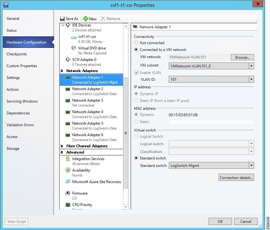
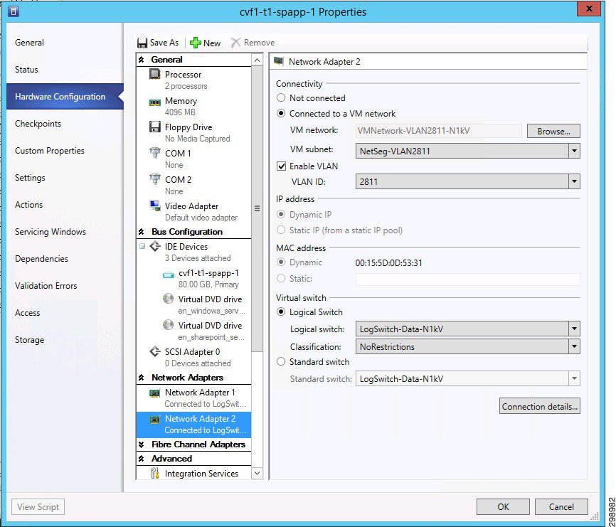
Create the Virtual Switch on all of the hosts in the cluster before assigning VM Networks to a VM’s interfaces. To use network resources from the Nexus 1000V, click on Hardware Configuration under the VM’s Properties page. Then perform the following steps.
1.![]() Click on Connected to VM network and browse for the correct selection. This will fill in the selection for VM subnet using the Network Segment that is configured on the Nexus 1000V.
Click on Connected to VM network and browse for the correct selection. This will fill in the selection for VM subnet using the Network Segment that is configured on the Nexus 1000V.
2.![]() If the Enable VLAN is active, select it and verify that the VLAN is correct.
If the Enable VLAN is active, select it and verify that the VLAN is correct.
3.![]() The Logical switch will be filled in. Make sure that the information is accurate.
The Logical switch will be filled in. Make sure that the information is accurate.
4.![]() The Classification field will be empty. You must select an entry for proper operation. Choose the Classification that was created in earlier steps.
The Classification field will be empty. You must select an entry for proper operation. Choose the Classification that was created in earlier steps.
5.![]() Click Ok to save the change.
Click Ok to save the change.
In some instances, the Hyper-V host may need to have an interface in a VLAN for management, monitoring, or replication traffic purposes. For example, in the validation testing, the Hyper-V hosts had an interface in the replication VLAN, which was used by the CommServe Manager to install a VSA on the hosts.
To configure an interface, select New Virtual Network Adapter under the Virtual Switches tab of the host properties window. The name you give the adapter will show up as a network connection on the host blade.
Figure 4-24 Host Virtual Interface Configuration
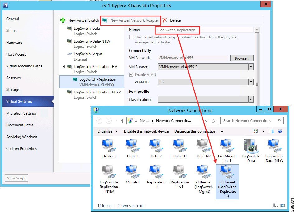
When adding a New Virtual Network adapter to the Hyper-V logical switch, configure and commit the switch before adding the New Virtual Network adapter. If it is configured at the same time, it could result in an error.
Refer to the following documents for details on deploying the Cisco Nexus 1000V in a Microsoft Hyper-V environment:
SAN Storage
Due to lab equipment availability, EMC VMAX Fibre Channel storage was presented to the Hyper-V cluster hosts in the SP1 site as various LUNs (datastores). The actual size and naming of these datastores was irrelevant to this project as these FC storage specifics were out of scope. CCA-MCP uses NetApp SAN storage in its architecture design.
Commvault Components
This section details the hardware used as Commvault infrastructure.
Compute
As discussed in the Architecture section above, each Commvault component is designed to be sized for the type of environment being supported. Here we will describe how each building block was sized and configured for the validation environments.
Storage
Network Attached Storage (NAS) will be used for the Disk Library storage required to retain the data for the tenants in the SP1. NAS is being used to allow for the sharing of the Disk Library between the two MediaAgents, providing failover and load balancing capabilities.
Networking
Generally each server within the CommCell will have two different network adapters, one strictly for management access to the server and one much faster network adapter used for the backup data traffic. The validation environment was setup following that standard with 1GbE adapters with 192.168.x.x addresses for the management network and 10GbE adapters with 10.5.x.x addresses for the backup network. Backup or replication traffic that is traversing the backup network will be utilizing TCP ports 8400 – 8402, as well as randomized ports for data transfer, which was limited to 32768 – 65535 when crossing the firewall to get to SP2 or the Enterprise site. The Backup Network will also be used for the presentation of the NFS File Shares from the NAS.
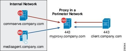
To allow for communication from external customer networks a Commvault Simpana Web Proxy will be used. The Commvault Simpana Web Proxy is a special proxy configuration where a dedicated iDataAgent is placed in a perimeter network, and the firewalls are configured to allow connections (from inside and outside networks) into the perimeter network. The proxy, which is the agent running in the perimeter network authenticates, encrypts, and proxies accepted tunnel connections to connect the clients operating outside to clients operating inside.
The Simpana proxy acts like a Private Branch Exchange (PBX) that sets up secure conferences between dial-in client calls. With this setup, firewalls can be configured to disallow straight connections between inside and outside networks.
Figure 4-25 shows a perimeter network setup where a client from outside communicates to the CommServe and MediaAgent operating in an internal network through the Simpana proxy.
Figure 4-25 Commvault Simpana Web Proxy
Physical Server Protection
This section describes the iDataAgents and their capabilities for the physical server types being protected at this location.
Windows File System iDataAgent
The Windows File System iDataAgent provides unified protection and recovery for file system data residing on Windows clients. In addition to complete protection of file system data for disaster recovery, the Windows File System iDataAgent also provides more granular backup and recovery options that operate seamlessly with your data protection. Further options for deduplication, job-management and reporting help to make sure that all of your file system data are easily traceable and retrievable whenever the need arises. The Windows File System iDataAgent offers the following key features:
The Windows File System iDataAgent enables easy management of all the Windows systems in your environment, by providing a singular approach to manage the data using the same unified console and infrastructure.
In the event of a serious system failure, such as the breakdown of hardware, software, or operating systems, the Windows File System iDataAgent provides point-in-time recovery of files at any given time.
The Windows File System system state contains many components and services that are critical to recovery of the Windows operating system. The system state is backed up and restored as part of Windows File System iDataAgent backup and restore.
The Office Communications Server contains data, settings, and metadata that are critical to data protection operations residing in both the File System and SQL databases. In order to fully protect the Office Communications Server, the OCS data settings and the OCS metadata must be backed up.
In the event that a MediaAgent used during a backup or recovery operation fails, the operation will automatically resume on an alternate MediaAgent from the point of failure. This is especially useful for backups and restores of large amounts of file system data.
In the event, that a network goes down, the backup and recovery jobs are resumed on alternate data paths. Similarly, in the event of a device failure, the jobs are automatically switched to alternate disk and tape drives.
You can view and verify the status of the backup and recovery operations from the Job Controller and Event Viewer windows within the CommCell Console. You can also track the status of jobs using reports, which can be saved and easily distributed. Reports can be generated for different aspects of data management. You also have the flexibility to customize the reports to display only the required data and save them to any specified location in different formats. For example, you can create a backup job summary report to view completed backup jobs at-a-glance. In addition, you can schedule these reports to be generated and sent by email without user intervention.
Deduplication provides a smarter way of storing data by identifying and eliminating the duplicate items in a data protection operation.
Deduplication at the data block level compares blocks of data from multiple files against each other. For example, if two or more files contain blocks of data that are identical to each other, then block level deduplication eliminates storing the redundant data thereby reducing the size needed for storage. This way also dramatically reduces the number of backup data copies on both disk and tapes.
1-Touch recovery helps to recover a crashed system in the least amount of time. By automatically rebuilding the operating system, you can recover systems with defective components such as inaccessible volumes or crashed disks. You don't need to reinstall the individual software packages or operating systems manually.
The Simpana OnePass is an integrated File System agent that backs up and archives the qualified data. Simpana OnePass also reclaims backup storage space when files and stubs are deleted on the primary storage.
Linux File System iDataAgent
Simpana software provides a simplified end-to-end protection of file system data residing on all the Linux computers in your enterprise. In addition to complete protection of file system data for disaster recovery, it also provides a robust and comprehensive backup and recovery solution with significant speed performance and efficient use of disk and tape drives. It also assists you in full system rebuilds and eliminates recovery failures. The Linux File System iDataAgents offers the following key features:
The Linux File System iDataAgents enables easy management of all the Linux systems in your environment, by providing a singular approach to manage the data using the same unified console and infrastructure.
In the event of a serious system failure, such as the breakdown of hardware, software, or operating systems, the Linux File System iDataAgent provides point-in-time recovery of files at any given time.
In the event that the MediaAgent used for the backup or recovery operation fails, the backup is automatically resumed on alternate MediaAgents. In such cases, the backup or restore job does not restart from the beginning, but resumes from the point of failure. This is useful for backups and restores of large amount of file system data.
In the event, that a network goes down, the backup and recovery jobs are resumed on alternate data paths. Similarly, in the event of a device failure, the jobs are automatically switched to alternate disk and tape drives.
You can view and verify the status of backup and recovery operations from the Job Controller and the Event Viewer within the CommCell Console. You can also track the status of the jobs using Reports, which can be saved and distributed. Generate reports for different aspects of data management. Customize the reports to display only the required data and save them to a specific location in different formats. For example, you can create a backup job summary report to view the completed backup jobs.
You can schedule, generate and send the Reports via email without user intervention.
Block-level backup is a faster method to back up data because only the extents that contain data are backed up, rather than the entire files.
Block-level backups provide better performance over file system backups and disk image-based backups if the file system has a large number of small files by reducing the scan times. Also, when compared to file system incremental backups, block-level incremental backups run faster and back up less data if the file system has very large files. By default, block-level backups are performed using native snaps, but they can be configured to function with hardware snap engines.
Deduplication provides a smarter way to store data by identifying and eliminating the duplicate items in a data protection operation.
Deduplication at the data block level compares blocks of data against each other. If an object (e.g., file, database) contains blocks of data that are identical to each other, then block level deduplication does not store the redundant data, which reduces the size of the object in storage. This reduces the size of the backup data copies on both the disk and tapes.
1-Touch recovery helps to recover a crashed system in the least amount of time. By automatically rebuilding the operating system, you can recover systems with defective components such as inaccessible volumes or crashed disks. You don't need to reinstall the individual software packages or operating systems manually.
The Simpana OnePass is an integrated File System agent that backs up and archives the qualified data. Simpana OnePass also reclaims backup storage space when files and stubs are deleted on the primary storage.
Content Indexing and Search enables users to content index their data and later search the data from a user-friendly web interface. The users can also perform restore operations or other advanced actions on the searched data.
Virtual Server Protection
This section describes the iDataAgents and their capabilities for the virtual environments being protected in this location.
Virtual Server iDataAgent for Hyper-V
The Virtual Server iDataAgent, or VSA, provides a unified protection and recovery vehicle for all virtual machine data in a Hyper-V cluster or a standalone Hyper-V server. In addition to complete protection of entire virtual machines for disaster recovery, the Virtual Server iDataAgent also provides granular backup and recovery options. The additional options such as customized automatic discovery, deduplication, and reporting ensure all your virtual machine data is easily traceable and retrievable whenever the need arises.
Figure 4-26 displays various components of Virtual Server iDataAgent and how the data flows:
Figure 4-26 Virtual Server iDataAgent Components and Data Flows
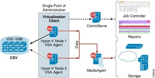
The Virtual Server iDataAgent offers the following key features:
The Virtualization client serves a single point of administration for all cluster nodes. All administration actives such backups, restores, schedules, reports etc can be performed from the Virtualization Client.
The cluster will be seamlessly backed up even if the virtual machine migrates from one host to another. The incremental backup cycles will also be maintained.
Once you configure the Virtual Server iDataAgent for a cluster or a server, all the virtual machines in the Hyper-V Cluster or server are automatically selected for backup. This behavior is designed to ensure all virtual machines are backed up.
If you want to backup only specific virtual machines in a cluster or a server, you can set criteria to search the virtual machines and automatically select them for backup. This is useful in environments where virtual machines are frequently added, or removed. You can easily browse and select objects such as CSV or Hosts to set criteria for automatic discovery.
If you want to exclude specific virtual machines from the backup, you can set criteria to filter virtual machines.
You can view a detail report about each backed up virtual machine. It contains information such as size of the data, status of integration services, guest operating system, the host on which the virtual machine is running etc. You can view all this information from the CommCell console when the backup job is running. It appears on the Virtual Machine Status tab of the View Job Details dialog box.
IntelliSnap Backup enables you to create a point-in-time snapshot of a virtual machine by temporarily stilling the data, taking a snapshot, and then resuming live operations. IntelliSnap backups work in conjunction with hardware snapshot engines.
Deduplication provides a smarter way of storing data by identifying and eliminating the duplicate items in a data protection operation.
Deduplication at the data block level compares blocks of data against each other. If virtual machines contains blocks of data that are identical to each other, block level deduplication eliminates storing the redundant data and reduces the size of the data in storage. This dramatically reduces the virtual machine backup data copies on both the disk and tapes.
Application Protection
This section describes the iDataAgents and their capabilities for the applications and databases protected in this location.
Microsoft SQL Server iDataAgent
The Microsoft SQL Server iDataAgent provides a simplified end-to-end backup and recovery solution for SQL data in your enterprise. The product can be used to perform both full system rebuilds and granular recovery of the data. Some of the key features of the SQL iDataAgent are:
The SQL iDataAgent provides the flexibility to backup the SQL database from different environments. You can perform a full or incremental backup of the entire instance, individual databases or files and file groups, and the transaction logs at any point of time as described below:
You can backup both the system and user-defined databases. You can comprehensively backup all the databases in an instance or schedule backups for the individual databases. You can also auto-discover new databases to comprehensively manage the backup of all databases in your environment.
Transaction log backups captures the transaction log whether the transaction was committed or not. The use of transaction log backups make point in time recovery possible. You can restore to any point in time within the transaction log.
Files or file group backups allows you to backup individual files or file groups. This functionality can be critically important, especially for large databases. Whereas a full database backup captures all files of a given database, file and file group backups allow you to back up selected portions of a database individually. As with database backups, the system provides the option of performing full, differential, and transaction log backups of file and file groups. Note that when running a transaction log backup for a File/File Group subclient, the database log is automatically backed up.
The SQL iDataAgent provides the ability to recover databases or entire SQL instance. There is no mounting, no recovery wizards, no extra steps needed – the software takes care of it all. This includes the following abilities:
–![]() Full or Partial Restore databases
Full or Partial Restore databases
–![]() Restore and replay transaction logs
Restore and replay transaction logs
–![]() Set Database state during restore (Recovery, Standby, No Recovery)
Set Database state during restore (Recovery, Standby, No Recovery)
You can view and verify the status of SQL backup and recovery operations from the Job Controller and Event Viewer windows within the CommCell Console. You can also track the status of the jobs using Reports, which can be saved and easily distributed. Reports can be generated for different aspects of data management. You also have the flexibility to customize the reports to display only the required data and save them to any specified location in different formats. For example, you can create a backup job summary report to view at-a-glance the completed backup jobs.
In addition, you can also schedule these reports to be generated and send them on email without user intervention.
In the event that a MediaAgent used for the backup or recovery operation fails, it is automatically resumed on alternate MediaAgents. In such cases, the backup or restore job will not restart from the beginning, but will resume from the point of failure. This is especially useful for backups and restores on large SQL databases.
In the event, that a network goes down, the backup and recovery jobs are resumed on alternate data paths. Similarly, in the event of a device failure, the jobs are automatically switched to alternate disk and tape drives.
Deduplication provides a smarter way of storing data by identifying and eliminating the duplicate items in a data protection operation.
Deduplication at the data block level compares blocks of data against each other. If an object (file, database, etc.) contains blocks of data that are identical to each other, then blocvk level deduplication eliminates storing the redundant data and reduces the size of the object in storage. This way dramatically reduces the backup data copies on both the disk and tapes.
SnapProtect Backup enables you to create a point-in-time snapshot by temporarily quiescing the data, taking a snapshot, and then resuming live operations. SnapProtect backups work in conjunction with hardware snapshot engines.
Microsoft SharePoint iDataAgent
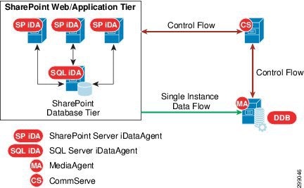
Microsoft SharePoint Server and Windows SharePoint Services include components that are backed up by the SharePoint Server iDataAgent, as well as data which must be backed up using the File System iDataAgent. SharePoint database files can also reside on separate SQL servers; to secure this data, you must back up these files using the appropriate SQL Server iDataAgent. The SharePoint entities that can be backed up by the system are described in detail in the following sections.
Figure 4-27 SharePoint Web/Application Tier
The SharePoint Server iDataAgent offers the following key features:
Document level backups allows capturing of system oriented metadata such based on parameters such as modified by or version information in a canned manner so that this backed up information can be brought back as it was backed up. In place merge options determines the current state of the target entities and intelligently determines what to restore. The customization on top of base template can also be seamlessly captured during backups.
Prior to v10, there were many options to choose from within a particular level of protection. Also there were less number of choices/strategies which optimized each level of protection. The backup and restore procedures in v10 have simplified the overall offerings as well as complexities and therefore the iDataAgent is more resilient against failures.
Snapshot of Content databases allows for faster backups of the SharePoint data. By using the offline browse and IntelliSnap feature, the same granularity of data can be recovered quickly from a snapshot.
All entities in the File System or IIS related to SharePoint are protected along with all logical SharePoint components.
Content database backups are fully RBS aware* and protect RBS blobs along with databases regardless of backup methods (streaming, VSS, or IntelliSnap).
Note![]() *Supports only Microsoft provided File Stream RBS provider.
*Supports only Microsoft provided File Stream RBS provider.
You can view and verify the status of the backup and recovery operations from the Job Controller and Event Viewer windows within the CommCell Console. You can also track the status of the jobs using reports, which can be saved and easily distributed. Reports can be generated for different aspects of data management. You also have the flexibility to customize the reports to display only the required data and save them to any specified location in different formats. For example, you can create a backup job summary report to view at-a-glance the completed backup jobs. In addition, you can also schedule these reports to be generated and send them on email without user intervention.
Deduplication provides a smarter way of storing data by identifying and eliminating the duplicate items in a data protection operation.
Deduplication at the data block level compares blocks of data against each other. If an object (file, database, etc.) contains blocks of data that are identical to each other, then block level deduplication eliminates storing the redundant data and reduces the size of the object in storage. This way dramatically reduces the backup data copies on both the disk and tapes.
Content Indexing and Search enables users to content index their data and later search the data from a user-friendly web interface. The users can also perform restore operations or other advanced actions on the searched data.
Oracle / Oracle RAC iDataAgent
The Oracle RAC iDataAgent provides a simplified end-to-end backup and recovery solution for Oracle databases in your enterprise without using multiple subclients and storage policies. Itv also allows you to load-balance Oracle backups and restores across multiple database nodes. The product can be used to perform both full system rebuilds and granular recovery of data and logs. Some of the key features are:
The Oracle RAC iDataAgent provides the flexibility to backup the Oracle database in different environments. This is very essential since the Oracle database is always subject to constant changes.
You can perform a full or incremental backup of the entire database or individual data files and tablespaces, and archive logs at any point in time. The following section describes the backups that can be performed in different environments.
In configurations where there is no RMAN catalog, the Oracle control file can be used as an alternative.
When the database is mounted, and not open or available for use, perform a full backup of the database without the archive logs. Use the offline backup when the data is consistent, and there are no transactions in the database.
When you cannot bring down the database to perform an offline backup, use the online backup method. Perform full or incremental backups when the database is online and in ARCHIVELOG mode. Use online backups to perform a point-in-time restore of the database.
You can also backup the archive logs only when the database is online. These logs can be applied to an online backup to recover the database to the current point-in-time.
You can also protect the non-database files and profiles using the appropriate File System iDataAgent.
You can backup and store copies of valid data from a source copy of a specific storage policy to all or one active secondary copy within a storage policy to provide a better tape rotation. An online full backup job is copied to a selective copy if the full backup job cycle completes successfully. This allows you to select, store and protect your valuable data on a secondary copy for future restores.
This iDataAgent allows you to group any desired number of Oracle iDataAgent instances under one or more Oracle RAC database logical entities. As such, Oracle backups and restores as well as other job types and functions (including Data Aging, Scheduling, Job Management) are all consolidated and easy to manage. This allows you to maintain your data irrespective of whether you add or remove Oracle iDataAgent instances from the RAC database.
You can configure various resources on the RAC nodes and include more number of streams for accelerated backup and restore.
In the event that the MediaAgent used for the backup or recovery operation fails, the backup is automatically resumed on alternate MediaAgents. In such cases, the backup or restore job does not restart from the beginning, but resumes from the point of failure. This is useful for backups and restores of large amount of file system data.
In the event, that a network goes down, the backup and recovery jobs are resumed on alternate data paths. Similarly, in the event of a device failure, the jobs are automatically switched to alternate disk and tape drives.
Also, this iDataAgent automatically checks the status of each Oracle instance during a backup or restore and allocates RMAN channels only for the instances that are active. Therefore, even if a specific instance fails, the backup or restore will continue.
You can view and verify the status of backup and recovery operations from the Job Controller and the Event Viewer within the CommCell Console. You can also track the status of the jobs using Reports, which can be saved and distributed. Generate reports for different aspects of data management. Customize the reports to display only the required data and save them to a specific location in different formats. For example, you can create a backup job summary report to view the completed backup jobs.
You can schedule, generate and send the Reports via email without user intervention.
Deduplication provides a smarter way to store data by identifying and eliminating the duplicate items in a data protection operation.
Deduplication at the data block level compares blocks of data against each other. If an object (e.g., file, database) contains blocks of data that are identical to each other, then block level deduplication does not store the redundant data, which reduces the size of the object in storage. This reduces the size of the backup data copies on both the disk and tapes.
In addition to using the CommCell Console, you can perform backup and restore operations from the command line using XML scripts or Qcommands. The options for backup and restore can be selected from the CommCell Console and saved as an XML file. Also, there are many downloadable XML file templates available in the documentation, which can be used to perform specific operations from the command line interface.
SP2 Site Overview
The Cloud Service Provider SP2 site was built to serve as the secondary CSP data center in this validation effort. It was integral in the In-Cloud BaaS use case where two tenants were deployed in SP1 with backups being done remotely to SP2.
IaaS Architecture
The data center infrastructure for the SP2 site is based on CCA-MCP, The CCA-MCP solution is a reference design that can be leveraged by enterprises and service providers to deploy an infrastructure that is efficient, secure, resilient, agile, simple, and scalable.
Cisco UCS
The Cloud Service Provider site SP2 used both UCS B-Series and C-Series compute hardware. The B-Series were used to deploy the Microsoft Hyper-V environment, including the infrastructure and production Hyper-V hosts. The C-Series were used to deploy the Commvault MediaAgents.
B-Series
The UCS B200 M2 and M3 servers were managed by the Cisco UCS Manager (UCSM) running release 2.1(1f). The Service Profile templates were configured to be the same as those described for Cloud Server Provider site SP1. Refer to SP1 Site Overview for a description of how the B-Series were deployed.
C-Series
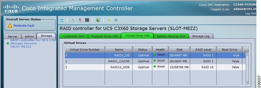
The UCS C3160 M3 servers were running release 2.0(2a). The C3160 M3 can only be managed in standalone mode and cannot be managed by the UCSM. The server had a UCS VIC 1227 configured with two vNICs for network connectivity and a RAID controller with (14) 4TB HDD.
Figure 4-28shows the RAID configurations that were used on the C3160 M3 for the MediaAgent. The first RAID was configured for RAID1 and was used for the Windows OS and Commvault MediaAgent software. The second RAID was also configured for RAID1 and used for a cache. The last RAID included ten physical drives in a RAID10 configuration and was used for the database.
Figure 4-28 Cisco UCS C3160 M3 RAID Configurations
The Commvault MediaAgents were connected to the infrastructure management via the LOM (LAN on Motherboard) and connected to the replication network via the UCS VIC1227. A virtual Ethernet (vNIC) interface was configured and connected to the Nexus 5548 access layer switch. For the SP2 site, the vNIC interface and the Nexus switchport were configured as trunk ports with a native VLAN set to VLAN56. Alternatively, the vNIC and Nexus switchport could be configured as access ports configured for VLAN56. The latter approach was used in the SP1 site.
Microsoft Hyper-V
The Hyper-V implementation in SP2 was similar to the implementation in SP1. A Hyper-V cluster was created for the management virtual machines and a production cluster was created for the tenant virtual machines. Virtual networking was initially implemented using native Hyper-V as per CCA-MCP deployment and automation model, but this lab implementation used an alternative approach by using Cisco Nexus 1000V for the production hosts by repurposing the UCS vNICs to the Nexus 1000V.
VSA agents are installed on two Hyper-V hosts in the cluster (cvf6-hyperv-3 & cvf6-hyperv-4) with the same resource Reserves that were allocated in SP1.
Refer to the SP1 section for an overview of the Hyper-V implementation and references. Refer to the Cisco Nexus 1000V later in this section for a discussion on how the migration of virtual networking was executed.
Cisco Cloud Services Router (CSR) 1000V
As in SP1, a unique CSR 1000V instance was deployed for each of the two tenants in SP2. The CSR 1000V was configured as the gateway for each of the VLANs used in the tenant workloads. In the validation testing, this included the web, application, and database VLANs. Since Layer 3 connectivity was used between the tenant CSRs at each site, unique IP subnets were configured to enable proper routing between sites. The CSRs used BGP routing to learn IP subnets connected to the remote site’s CSR. For the In-Cloud BaaS tenants (Tenants 1-2), an IPsec tunnel was not configured since the network path between the two CSP sites was considered secure.
Cisco Nexus 1000V
In SP2, native Microsoft Hyper-V switching was initially deployed per CCA-MCP automation and deployment model. At a later time, this was changed over to a Nexus 1000V distributed switch. The installation and integration is similar to the roll out for Cloud Services Provider site SP1. Refer to SP1 Site Overview for details.
SAN Storage
Due to lab availability, EMC VMAX Fibre Channel storage was presented to the Hyper-V cluster hosts in the SP2 site as various LUNs (datastores). The actual size and naming of these datastores was irrelevant to this project as these FC storage specifics were out of scope.
Commvault Components
This section details the hardware used as Commvault infrastructure.
Compute
As discussed in the Architecture section, each Commvault component is designed to be sized for the type of environment being supported. Here we will describe how each building block was sized and configured for the validation environments.
Storage
Direct Attached Storage (DAS) is being used for the Disk Library storage with these two MediaAgents. Above and beyond the disk required for the OS, Index Cache, and DDB, there are 8 4TB Drives configured in a RAID10 array that will be used for the Disk Library space. Since the disk is not shared between the two MediaAgents, cvf6-ma-1 will be used as the target for the Long-Term data replication, while cvf6-ma-2 will be used as the target for the Short-Term data replication.
Networking
As previously mentioned, each server within the CommCell will have two different network adapters, one strictly for management access to the server and one much faster network adapter used for the backup data traffic. The validation environment was setup following that standard with 1GbE adapters with 192.168.x.x addresses for the management network and 10GbE adapters with 10.5.x.x addresses for the backup network. Backup or replication traffic that is traversing the backup network will be utilizing TCP ports 8400 – 8402, as well as randomized ports for data transfer, which was limited to 32768 – 65535 when crossing the firewall to get to SP1.
Virtual Server Protection
This section describes the iDataAgents and their capabilities for the virtual environments being protected in this location.
Refer to SP1 Site Overview for Hyper-V.
Enterprise Site Overview
The Enterprise site was built to serve as the client enterprise data centers in this testing effort.
Architecture
For this release of the BaaS solution, the Enterprise data center architecture was unspecified and intended to be a generic enterprise architecture. In actuality, we leveraged an existing CCA-MCP test lab topology and used multitenancy to cover the various tenants required for validation testing.
Tenant 5 (Microsoft Hyper-V)
The Hyper-V implementation in Enterprise client Tenant 5 was similar to the implementation in SP1. A Hyper-V cluster was created for the management and tenant virtual machines.
VSA agents are installed on two Hyper-V hosts in the cluster (cvf8-hyperv-2 & cvf8-hyperv-3) with the same resource Reserves that were allocated in SP1. Refer to the SP1 section for an overview of the Hyper-V implementation and references.
A unique tenant-specific CSR 1000V instance was deployed for the Tenant 5. The CSR 1000V was configured as the gateway for each of the VLANs used in the tenant workloads. In the validation testing, this included the web, application, and database VLANs. An IPsec tunnel was configured between the CSR 1000V and another tenant-specific CSR 1000V at the SP1 site. The tunnel provided secure communications between the workload VLANs at each site.
Tenant 6 (RHEL OpenStack)
The Enterprise Tenant 6 site used OpenStack Icehouse built on RHEL 7 for compute. The tenant was built using two identical UCS B200 M3 servers in the Enterprise site, the specs for which are shown in Table 4-2 .
|
|
|
|
|
|
|---|---|---|---|---|
Each host had two vNICs, one for data VLANs and one for the management VLAN, as shown in Table 4-3 .
|
|
|
|
|---|---|---|
The management vNIC was used to provide connectivity to the Horizon management portal while the data vNIC was used to provide connectivity to the internal VLANs and the Commvault replication network.
The host cvf8-t6-ostck-1 was deployed as the OpenStack control node, running the base management services such as Horizon, Glance, Ceilometer, etc. The host cvf8-t6-ostck-2 was deployed as the OpenStack compute node, where the instances (virtual machines) would be deployed.
Figure 4-29, a screenshot of the network topology taken from the Horizon dashboard, shows how this OpenStack tenant was configured. Four networks were configured. Three (Web, App, DB) were configured to mimic a tenant’s 3-tier application deployment. The fourth network was the replication network used for backup of the instances via the Commvault Simpana software.
Five instances (called cvf8-test-centos-[1,2,3,4,5]) were deployed in this OpenStack environment, each running CentOS 7. Each instance was connected to two networks, the Replication network and the Web network. A Neutron router was configured to provide Layer 3 connectivity between the three application tiers.
Figure 4-29 Tenant 6 Openstack Network Topology
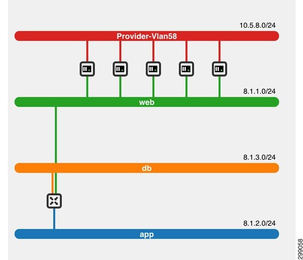
In Tenant 6, the tenant compute was isolated within the OpenStack cloud environment, with its only connectivity to the CSP clouds being on VLAN 58, the Commvault replication network. The gateway for VLAN 58 was configured using HSRP on the Enterprise aggregation switches.
Tenant 7 (VMware vSphere)
Enterprise client Tenant 7 was the only site to use vSphere. vSphere version 5.1 with vCenter, ESXi hosts, and Standard Switches were configured to deploy the required Commvault components, Cisco CSR 1000V, and client virtual machines.
VMware also requires the use of VSA agents. These are not directly loaded on the VMware hosts, but are Windows VMs that are configured with the Virtual Server Agent software. In this solution, Figure 4-30 shows resources reserved, VSA agents cvf8-t7-test-win-1 and cvf8-t7-test-win-1, in Enterprise Tenant 7.
Figure 4-30 VMware VSA Resource Allocation
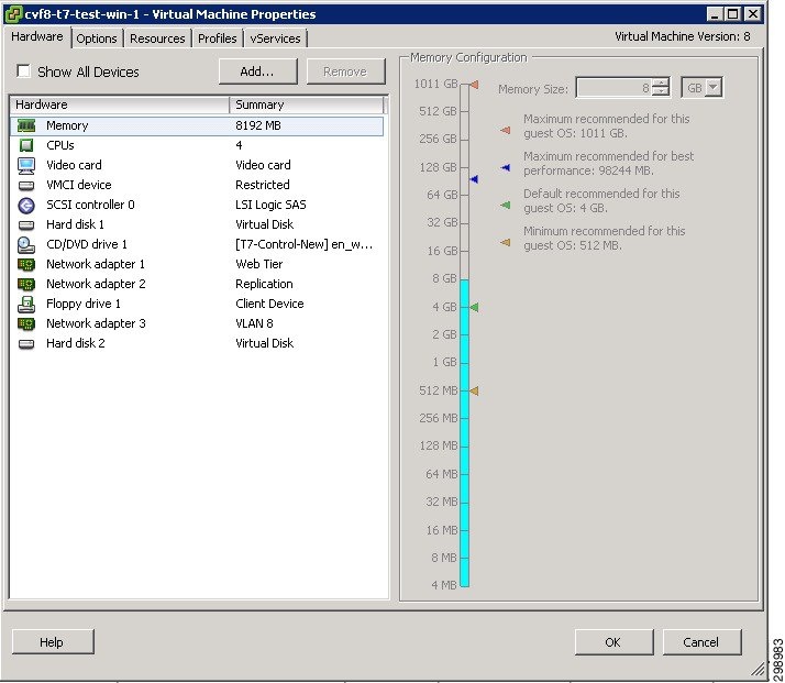
Refer to the following link for more information on Commvault Virtual Server Agent for VMware.
VMware Building Block Guide—Virtual Server Agent for VMware
A unique tenant-specific CSR 1000V instance was deployed for Tenant 7. The CSR 1000V was configured as the gateway for each of the VLANs used in the tenant workloads. In the validation testing, this included the web, application, and database VLANs. An IPsec tunnel was configured between the CSR 1000V and another tenant-specific CSR 1000V at the SP1 site. The tunnel provided secure communications between the workload VLANs at each site.
SAN Storage
Due to lab availability, EMC VMAX Fibre Channel storage was presented to the Hyper-V cluster hosts, OpenStack hosts, and the VMware hosts in the Enterprise site as various LUNs (datastores). The actual size and naming of these datastores was irrelevant to this project as these FC storage specifics were out of scope.
Commvault Components
This section details the hardware used as Commvault infrastructure.
Compute
As discussed in the Architecture section above, each Commvault component is designed to be sized for the type of environment being supported. Here we will describe how each building block was sized and configured for the validation environments.
Storage
Direct Attached Storage (DAS) is being used for the Disk Library storage with these two MediaAgents. Above and beyond the disk required for the OS, Index Cache, and DDB, there are 8 4TB Drives configured in a RAID10 array that will be used for the Disk Library space. Since the disk is not shared between the two MediaAgents, cvf6-ma-1 will be used as the target for the Long-Term data replication, while cvf6-ma-2 will be used as the target for the Short-Term data replication.
Networking
As previously mentioned, each server within the CommCell will have two different network adapters, one strictly for management access to the server and one much faster network adapter used for the backup data traffic. The validation environment was setup following that standard with 1GbE adapters with 192.168.x.x addresses for the management network and 10GbE adapters with 10.5.x.x addresses for the backup network. Backup or replication traffic that is traversing the backup network will be utilizing TCPPorts 8400 – 8402, as well as randomized ports for data transfer, which was limited to 32768 – 65535 when crossing the firewall to get to SP1.
Tenant 5 however will be configured to gain access to the CommServe and MediaAgent via the Web Proxy Server as mentioned in the SP1 section. This will limit network activity to Port 8403, with the option of allocating additional ports to increase performance.
Virtual Server Protection
This section will describe the iDataAgents and their capabilities for the virtual environments being protected in this location.
Commvault Simpana doesn’t currently have hypervisor level integration with RHEL OpenStack, but virtually all standard File System and Application Agents can be install directly in the Guest Operating System. For this case we’ll be using the Linux File System iDA, see description in SP1.
Virtual Server iDataAgent for Hyper-V
Refer to SP1 Site Overview.
Virtual Server iDataAgent for VMware
The Virtual Server Agent for VMware provides a unified protection and recovery vehicle for all virtual machine data in your vCenter. In addition to complete protection of entire virtual machines for disaster recovery, the Virtual Server Agent provides more granular backup and recovery options. Options such as customized automatic discovery, deduplication, and reporting ensure all your virtual machine data is easily traceable and retrievable whenever the need arises.
Figure 4-31 displays components and data flows for the Virtual Server Agent.
Figure 4-31 Virtual Server Agent Components and Data Flows
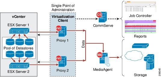
The Virtual Server Agent offers the following key features:
The virtualization client serves a single point of administration for all proxies. The proxy computer can be any computer where Virtual Server Agent is installed. All administration activities such as backups, restores, schedules, and reports can be performed from the virtualization client.
The virtualization client also enables proxy teaming. The proxy teaming ensures the fault tolerant backup. It will be useful when you want to perform the backup for a large number of virtual machines in a limited backup window
Once you configure the Virtual Server Agent for a vCenter, all the virtual machines in the vCenter are automatically selected for backup. This behavior is designed to ensure all virtual machines are backed up.
If you want to backup only specific virtual machines in a vCenter, you can set criteria to search the virtual machines and automatically select them for backup. This is useful in environments where virtual machines are frequently added, or removed. You can easily browse and select vCenter objects such as hosts, datastores, resource pool etc. to set criteria for automatic discovery.
You can exclude specific virtual machines or disks on the virtual machines from the backup. You can add filters for the virtual machines or disks.
You can view a detail report about each backed up virtual machine. It contains information such as name of the proxy which performed the backup of the virtual machine, size of the backup data, type of backup etc. You can view all this information from the CommCell console when the backup job is running. It appears on the Client Status tab of the View Job Details dialog box.
You can protect the vCloud-specific attributes of a virtual machine and restore it back to a vCloud.
IntelliSnap Backup enables you to create a point-in-time snapshot of a virtual machine by temporarily quiescing the data, taking a snapshot, and resuming live operations. IntelliSnap backups work in conjunction with hardware snapshot engines.
Deduplication provides a smarter way of storing data by identifying and eliminating the duplicate items in a data protection operation.
Deduplication at the data block level compares blocks of data against each other. If virtual machines contains blocks of data that are identical to each other, block level deduplication eliminates storing the redundant data and reduces the size of the data in storage. This dramatically reduces the virtual machine backup data copies on both the disk and tapes.
Changed Block Tracking (CBT) is a VMware feature that can be used to optimize backups of virtual machines by reading only the allocated and modified portions of a virtual disk. CBT is automatically enabled for virtual machines running on hardware version 7 or higher.
Site Interconnect Overview
For the purposes of this validation, the interconnect between the CSP and Enterprise sites was treated as a black box, since it was not in scope for this project.
Each of the two CSP sites and the Enterprise site (where the three Enterprise tenants were configured) were connected (single-homed) over IP into a generic Internet cloud which consisted of a pair of Cisco Catalyst 6500 multilayer switches. IP-based routing (BGP and OSPF) was configured to enable routing between sites.
IPsec tunneling was configured for Tenants 5 and 7 to connect the tenant containers in the Enterprise site to their respective containers in the SP1 site. The CSR 1000V routers deployed in each tenant container provided the endpoints for these encrypted tunnels. No encryption was configured for Tenants 1 and 2 between the SP1 and SP2 sites, following the assumption that the CSP would have encryption configured between sites at another layer. Refer to SP1 Site Overview for a discussion on the Cisco CSR 1000V.
Figure 4-32shows the interconnections between the Enterprise and SP1 in addition to SP1 to SP2. The routing table entries for the CSR pairs learned through BGP are shown next to each CSR. Routes for the local data center are learned via OSPF and are not shown here.
Figure 4-32 Site Interconnect Using Cisco Cloud Services Router (CSR) 1000V
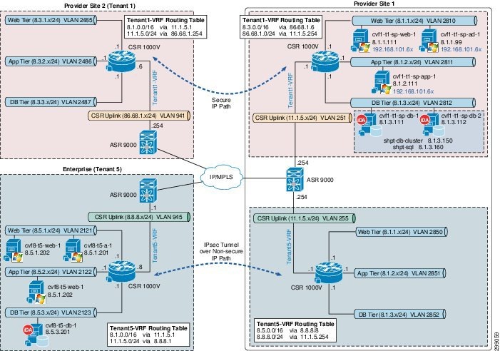
In Tenant 6, the tenant compute was isolated within the OpenStack cloud environment, with its only connectivity to the CSP clouds being on VLAN 58, the Commvault replication network. The gateway for VLAN 58 was configured using HSRP on the Enterprise aggregation switches.
Use Case 1 (In-Cloud BaaS): Implementation Details
The first use case is Cloud Backup and is focused on Enterprise customers that have their entire environment hosted at a Cloud Service Provider site. In such a case, the Enterprise production environment is hosted at one CSP site and the CSP leverages Commvault MediaAgent to perform local backups within that site as well as perform remote backups to a Commvault MediaAgent at a secondary site. Two tenants were created to proof this use case. Both of the tenants were managed within a single Hyper-V environment in the SP1 site. Figure 4-33 shows the environment used to proof this use case. Each iDA will interact with the CommServe and appropriate MediaAgent on a schedule basis to execute data protection jobs. The Primary copy of data will be stored locally on the MediaAgent that executed the backup job, but will then be DASH (deduplicated replication) copied to a MediaAgent in the secondary data center to provide for Disaster Recovery. The CVLT Database and Reporting Server are also protected and prepped for recovery at the secondary data center. Restoration of the data that is protected can be achieved at either data center.
Figure 4-33 Use Case 1 (In-Cloud BaaS) Implementation Topology
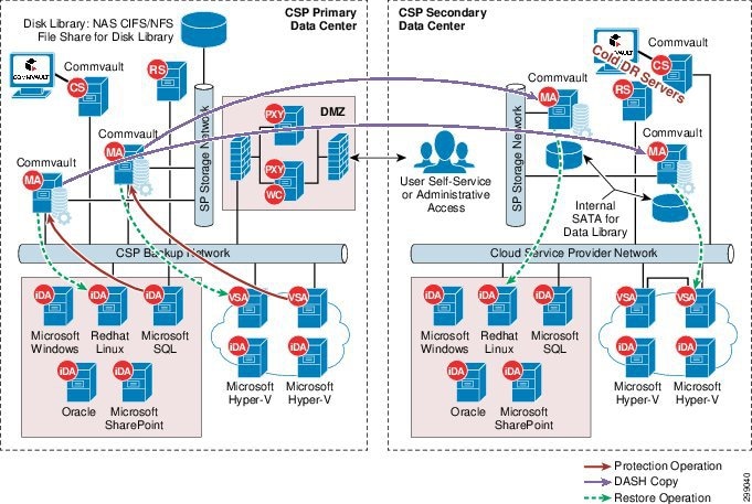
Tenant Details
Tenants 1 and 2 were configured virtually identically, with the exception of the applications represented within each.
Tenant 1 Application
In Tenant 1, the application used for testing purposes was Microsoft SharePoint with a Microsoft SQL database. A stand-alone instance of SharePoint 2013 was installed on a VM with a local database. The VM was configured with a single interface in the tenant workload web tier. Connectivity between the VM and the Commvault MediaAgent was enabled by the Cisco ASA 5585, with BGP route leaking to enable routing between the replication VRF and tenant VRFs.
In addition to the SharePoint instance, a Microsoft Windows 2012 R2 Failover Cluster was created and then SQL 2012 R2 was installed on the cluster. The cluster consisted of two Windows 2012 R2 VMs, each with their own 40GB C: drives and two additional shared volumes. The first shared volume was a 1GB quorum drive that was used for management of the cluster. The second shared volume was a 100GB data drive that was used for the database data.
In the VM configuration, these two shared drives were configured on a second SCSI controller that required a sharing mode to be enabled to allow sharing across multiple Hyper-V hosts. The sharing mode can only be configured from the Failover Cluster Manager on the Hyper-V host where the SQL VMs are running. The two VMs were configured with two interfaces each, one for the tenant workload database VLAN and a second for the replication VLAN. The virtual IP addresses for the cluster and for the SQL instance were configured on the database VLAN. The SQL database was populated with a test database and SQL scripts were used add/remove/count data in the database.
Tenant 2 Application
In Tenant 2, the application used for testing purposes was Linux Oracle 11g. A single Oracle RedHat Linux 6.6 VM was created and then Oracle 11g was installed on the VM. The VM was configured with two interfaces, with one connected to the tenant workload database VLAN and the other connected to the replication VLAN. The Commvault components in SP1 were also configured on the replication VLAN and this enabled Layer 2 connectivity between the MediaAgents and the Oracle database VM.
Commvault Configuration
This section details how the Commvault Infrastructure and Data Protection agents were configured for this use case.
Commvault Infrastructure
This section describes how each component of the Commvault Simpana is installed and configured.
CommServe Server
The CommServe is the primary server in the data protection environment, so it of course is the first server that is built out. There is also a stand-by CommServe that will be pre-staged in a recovery data center, its installation process is the same as the primary. On a Windows Server 2008 Standard server with the disk laid out for the Commvault CommCell Database, disable the firewall and install IIS and NET Framework 3.5.x, which are prerequisites to the Commvault CommServe software installation. Choose the custom installation method once starting the installation wizard. Select the CommServe, Consoles, Web Server, and Work Flow platforms. Further in the Wizard Choose the name for the CommServe.
Figure 4-34 CommServe Server Setup
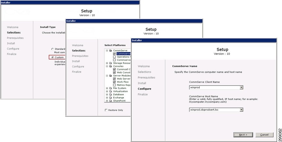
Also within the wizard, choose the location where the Commvault CommCell DB will reside, generally higher speed disk in an isolated array, setup the first Administrative User Account, and configure the location of where the Software Cache, used to install other Commvault infrastructure servers.
Figure 4-35 Setup Administrative User Account
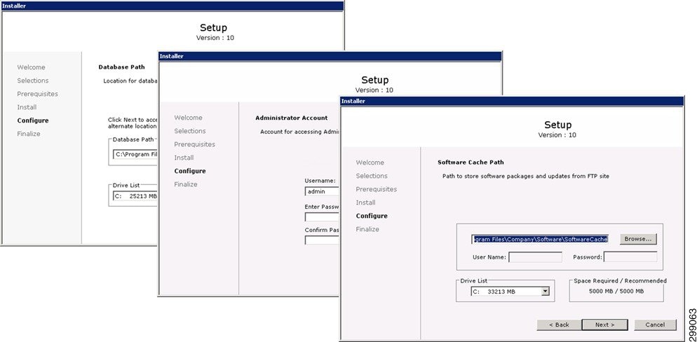
Once the installation is complete the Commvault Administrative Console will provide access to all Commvault activities (Figure 4-36).
Figure 4-36 Commvault Administrative Console
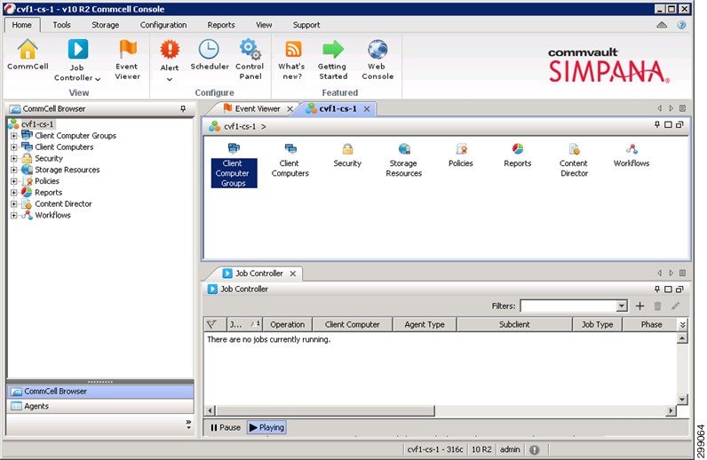
The only remaining step is to configure Commvault Disaster Recovery Backup Configuration (Figure 4-37), which is what is required in the event of a loss of the CommServe server itself. Generally this would be to a network drive or a shared volume mounted from the DR CommServe.
Figure 4-37 Commvault Disaster Recovery Backup Configuration
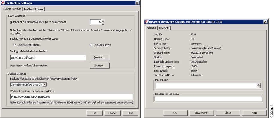
Refer to Commvault documentation for more information the CommServe.
MediaAgent Server(s)
The MediaAgent server is the data mover within the CommCell so it is the next server that needs to be built out. All connections to the actual storage, as well as the control of the deduplication is handled by the MediaAgent. The MediaAgents should have disk volumes created for the Operating System, CVLT DDB and Index Cache. They are then loaded with Windows 2012. The installation of the MediaAgent software can be pushed from the CommServe. In this case there are two MediaAgents, cvf1-ma-1 and cvf1-ma-2.
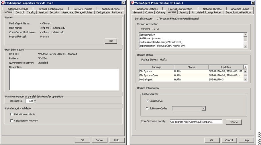
A Shared Disk Library is created from NFS File Share on both CVF1-MA-1 and CVF1-MA-2.
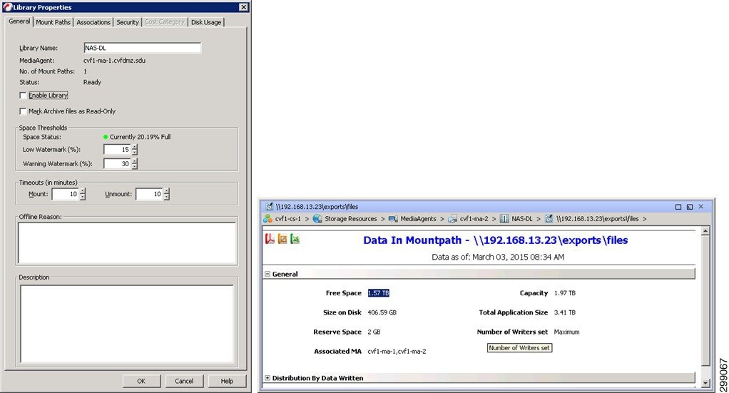
A Global Partitioned DDB is then created to frontend the NAS-DL just created.
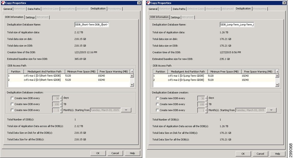
Finally the Tenant Storage Policies are configured.
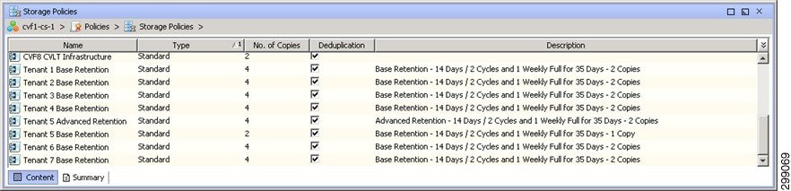
Refer to Commvault documentation for details on the MediaAgents.
Enterprise Metrics Reporting Server
The Commvault Simpana Enterprise Metrics Reporting Server collects data from all CommCells within an Enterprise or Service Provider’s environment, allowing for a wide breath of reporting capabilities. The Commvault Simpana Custom Report tool allows for the creation of very customized reports, as well as access to the Commvault Software Store, where written reports are made available. This server will have a separate MSSQL DB for the reporting data, so it should have some high speed disk allocated for this. It will be a Windows Server and require NET 3.5 and IIS before installing Commvault. There is also a stand-by server at a recovery site, its installation process is the same. Then the server can be installed, patched, and configured.
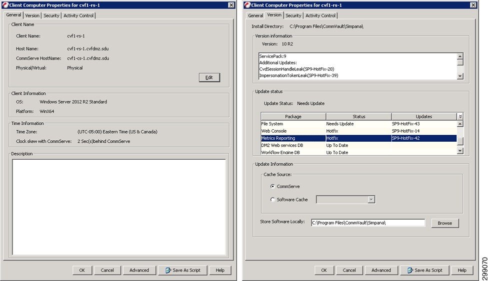
The Enterprise Metrics Reporting is configure via the administrative control panel.
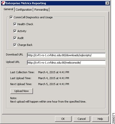
Refer to Commvault documentation for details on the Enterprise Metrics Reporting Server.
Web Proxy and Web Console Server
Proxies are an important component of service provider’s network security configuration to reduce the number of ports opened and provide secure data transfer between service provider and tenant. In this case a Shared Proxy is used as it will provide a single proxy with multiple tenants pooled together, be located in the service provider’s DMZ, and prevents the service provider’s infrastructure from being internet facing,. This server will also function as the Web Console allowing access to the environment to administrators and users, without exposing the CommCell to the outside world. CVF1-DMZ-PROXY-1 has the File System iDA installed and is patched to the latest version.
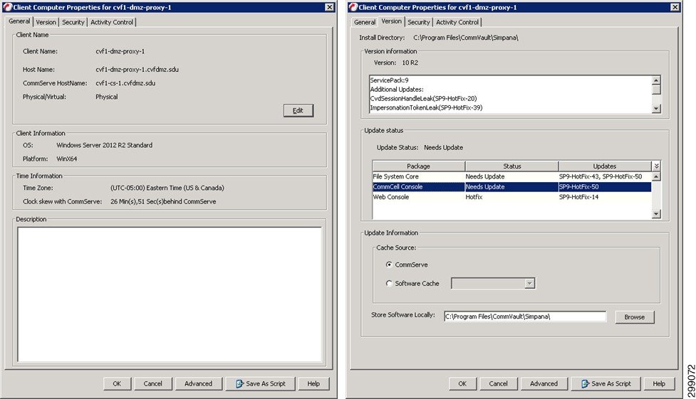
Configure the Web Proxy Server Firewall settings.
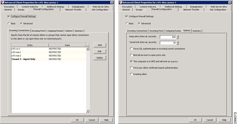
The CommServe firewall settings will then be updated
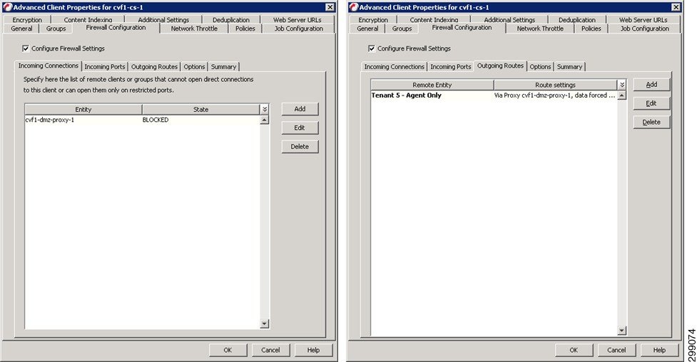
As well as the MediaAgent(s), that will be visible via the Web Proxy, Firewall settings.
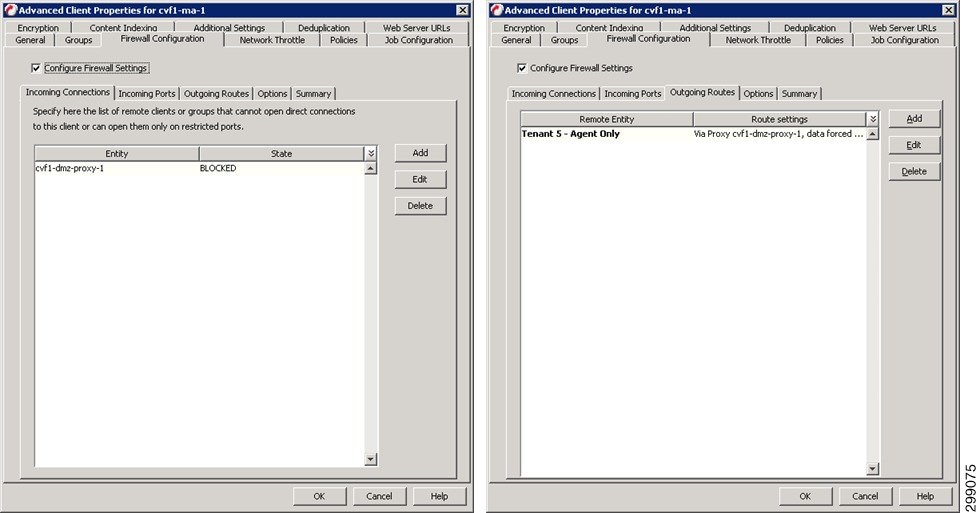
Finally, the Tenant Client Computer Group that will be accessing the CommCell via the Web Proxy, Firewall settings.
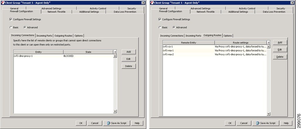
Use the eMail and Web Server configuration button in the control panel to configure the new Web Console.
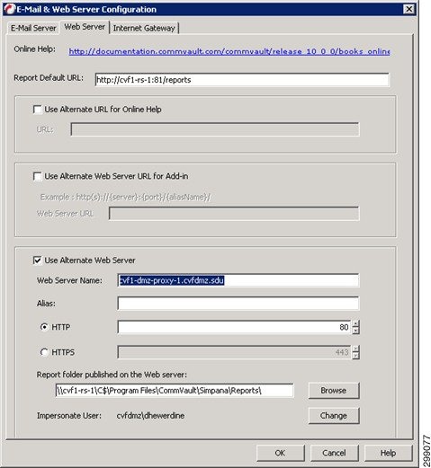
Access the Web Console via any browser.
Refer to Commvault documentation for details on the Web Proxy.
Refer to Commvault documentation for details on the Web Console.
Physical Server Protection Configuration
This section details how the iDataAgents were configured to provide data protection to the physical servers in this use case.
Windows File System iDA
The Windows File System iDA will be installed on each Window server requiring data protection from the File System level. Once the Client requiring protection is defined to the CommCell, the appropriate iDA can then be installed and configured.
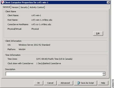
The Default File System Subclient will then be assigned to the proper Tenant Retention Storage Policy.
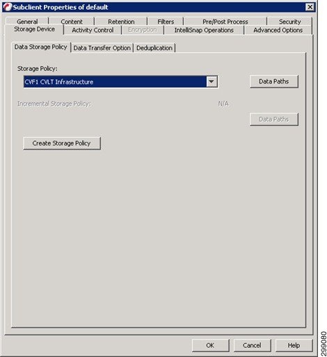
The Client is then associated to the proper Schedule Policy. The protected clients will be running an incremental backup nightly, while generating a synthetic full backup once a week.

Alerts can be configured against a given Schedule Policy allowing the control of who gets alerts for each different policy. Select the alert criteria to use.
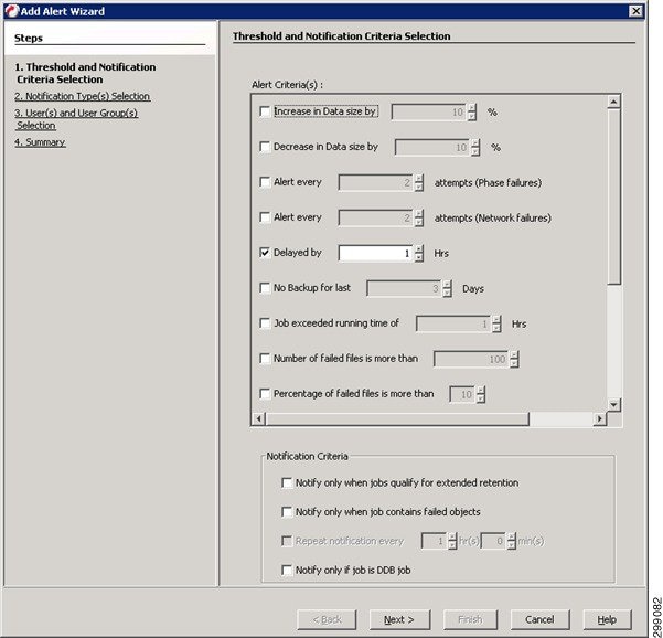
Select the notification method.
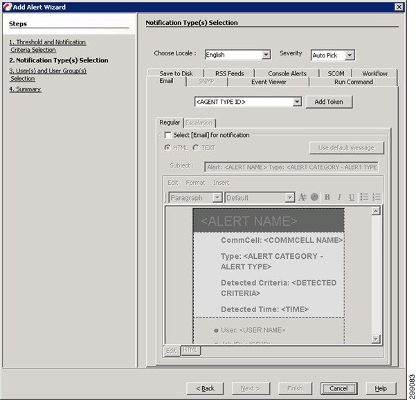
Select the Users or User Groups that will receive the alert.
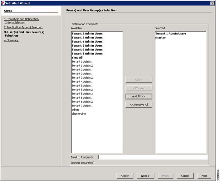
Refer to Commvault documentation for details on the Windows File System iDA.
Linux File System iDataAgent
The Linux File System iDA will be installed on each Linux server requiring data protection from the File System level. Once the Client requiring protection is defined to the CommCell and then the appropriate iDA can be installed and configured.
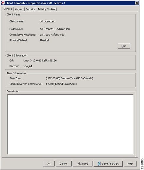
The Default File System Subclient will then be assigned to the proper Tenant Retention Storage Policy.
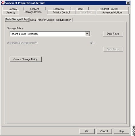
Now the Client is associated to the proper Schedule Policy. The protected clients will be running an incremental backup nightly, while generating a synthetic full backup once a week and alerts can be configured against a given Schedule Policy allowing the control of who gets alerts for each different policy. Refer to the Alert configuration for Windows File System iDA, above.
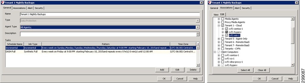
Refer to Commvault documentation for details on the Linux File System iDA.
Virtual Server Protection Configuration
This section details how the iDataAgents were configured to provide data protection to the virtual environments in this use case.
Virtual Server iDataAgent for Hyper-V
The VSA for Hyper-V is installed on one or more of the Hyper-v servers in the Hyper-V Cluster. The Hyper-V server that will be used as the VSA is defined to the CommCell, the required iDAs are installed and updated to the latest levels.
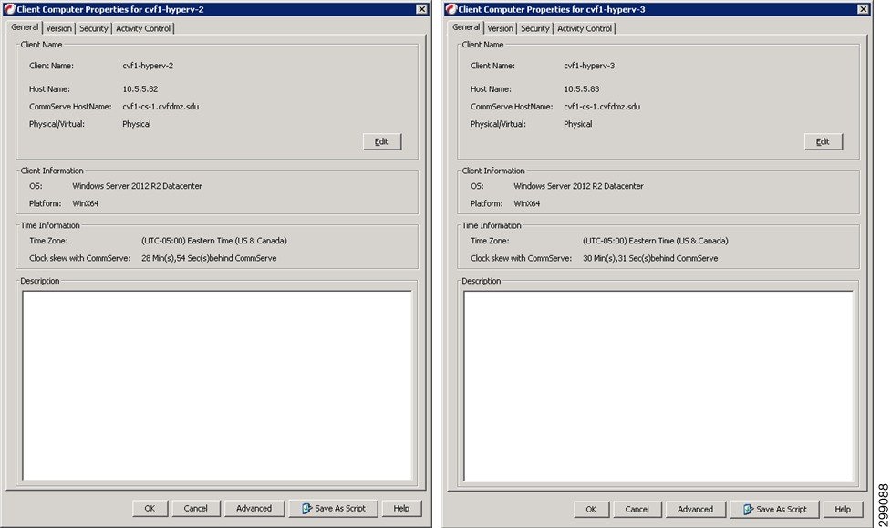
Once the VSA are installed, define a new Hyper-V Client, providing credentials and designating the VSA Servers to use.
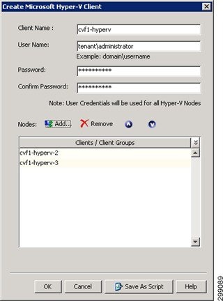
Create a new subclient for the Tenant Guests and select the VMs that will be protected for this Tenant.
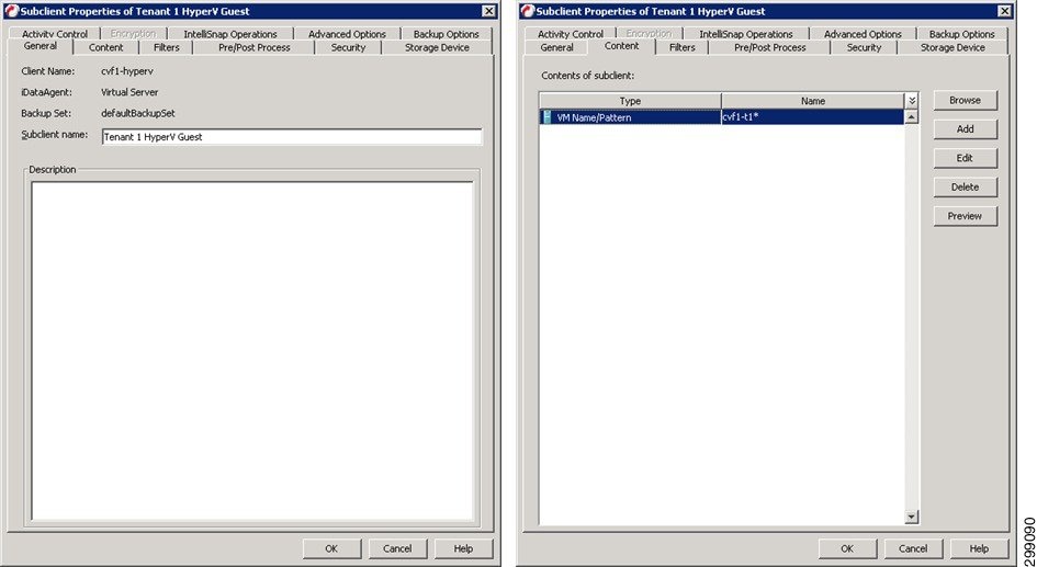
Select the appropriate Tenant Storage Policy.
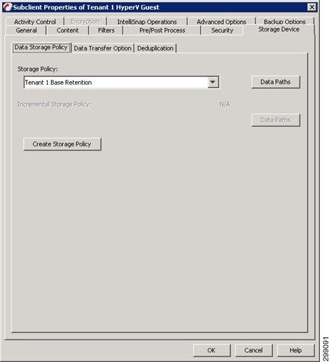
Finally the Client is associated to the proper Schedule Policy and alerts can be configured against a given Schedule Policy allowing the control of who gets alerts for each different policy. Refer to the Alert configuration for Windows File System iDA, above.
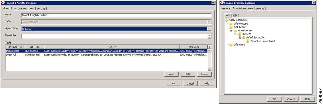
Refer to Commvault documentation for details on the Virtual Server iDA for Hyper-V.
Application Protection Configuration
This section details how the iDataAgents were configured to provide data protection for the applications and databases in this use case.
Microsoft SharePoint iDA
The Microsoft SharePoint iDA is going to be installed on any SharePoint server, whether they are virtual or physical servers, that require SharePoint Farm, Site, or Document level data protection. For this use case, SharePoint has all of its components installed on the same server. That server requiring protection is defined to the CommCell and then the appropriate iDAs can be installed, updated, and configured.
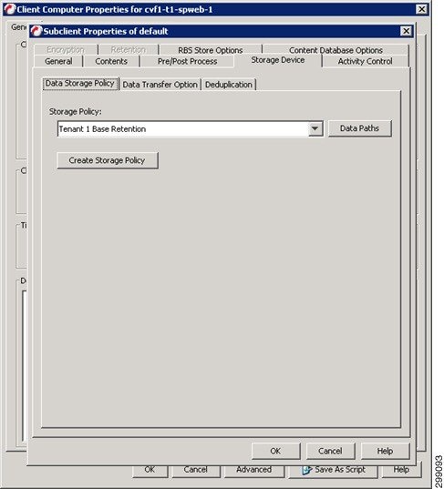
SharePoint has two levels of backups Database and Document. First configure the SharePoint Database default subclient to protect the entire Farm.
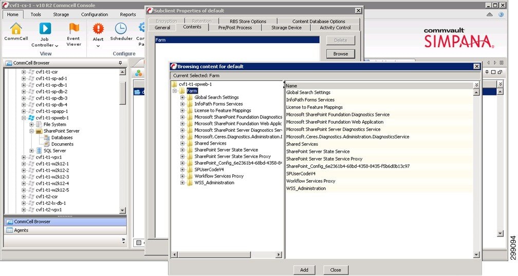
Assign it to the proper tenant Storage Policy.
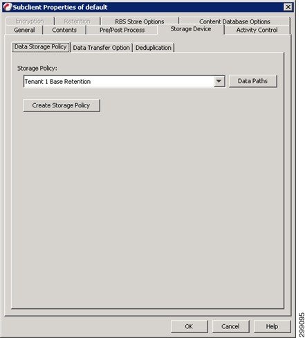
Configure the SharePoint Document default subclient to protect All Folders.
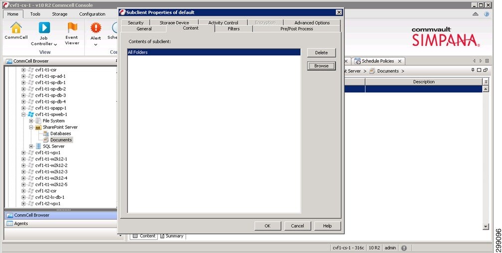
Assign it to the proper tenant Storage Policies:
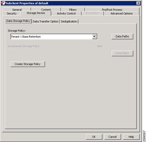
The Client is now associated to the proper Schedule Policy. SharePoint can have multiple different protection methods. In this example we have a Schedule Policy for the Database protection and another Schedule Policy for the Document protection. Alerts can be configured against a given Schedule Policy allowing the control of who gets alerts for each different policy. Refer to the Alert configuration for Windows File System iDA, above.
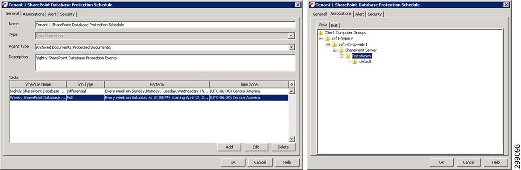
Refer to Commvault documentation for details on the Microsoft SharePoint iDA.
Microsoft SQL Server iDA
The Microsoft SQL Server iDA is going to be installed on any SQL server, whether they are virtual or physical servers, that require SQL DB, Table, and Log level data protection. For this use case, a two node cluster has been configured to run SQL. The servers requiring protection are defined to the CommCell and then the appropriate iDAs can be installed, updated and configured.
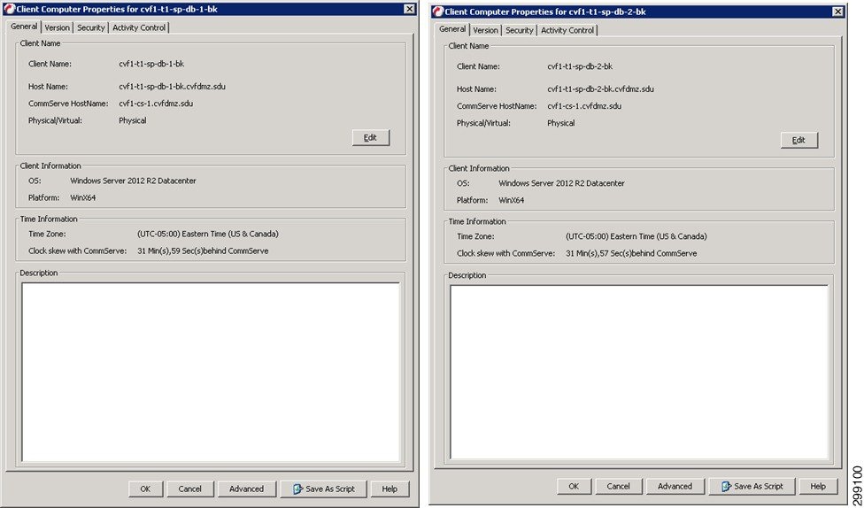
Define a new Windows Cluster Client, providing credentials and designating the VSA Servers to use.
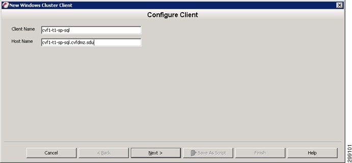
Define the servers that are part of the cluster.
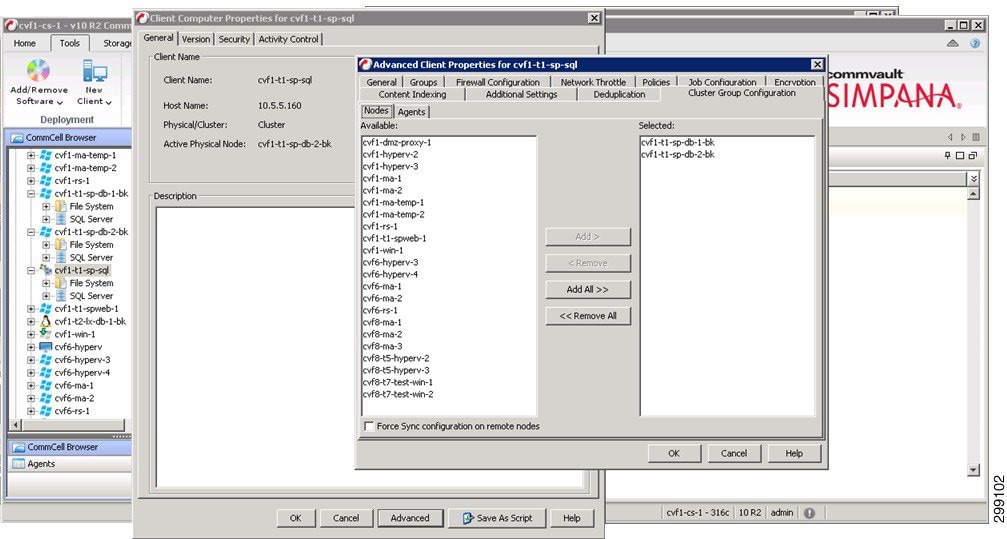
Define the iDAs that will be protecting this cluster, in this case just the SQL iDA.
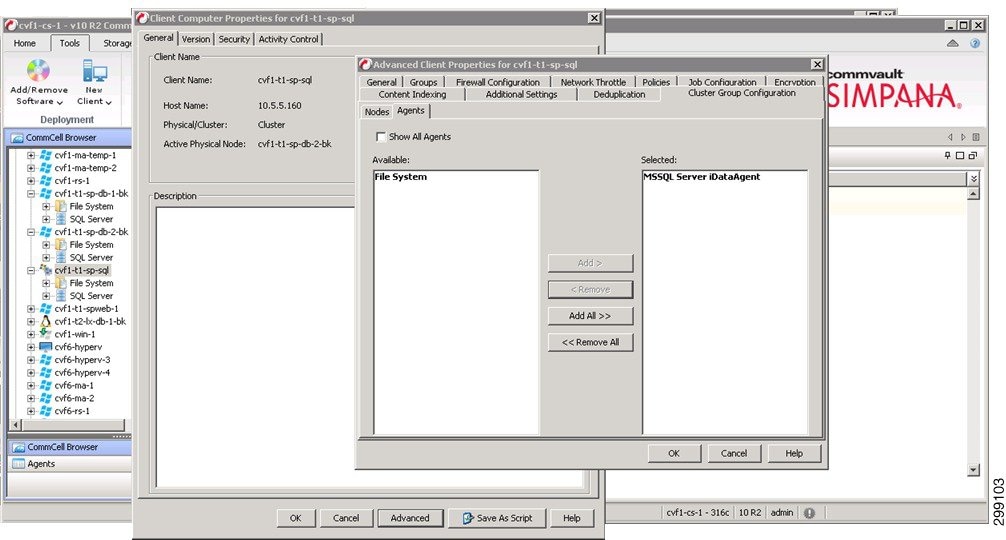
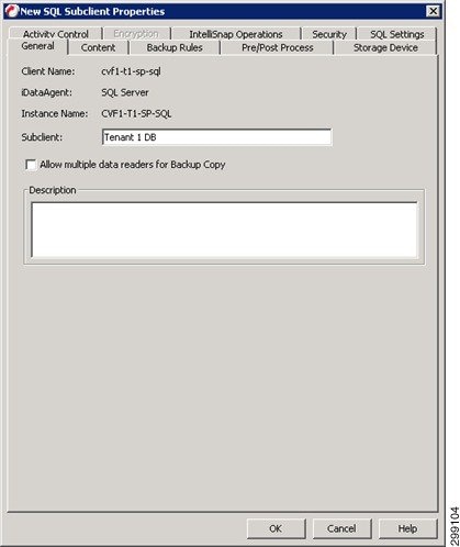
Assign the Databases to the new subclient.
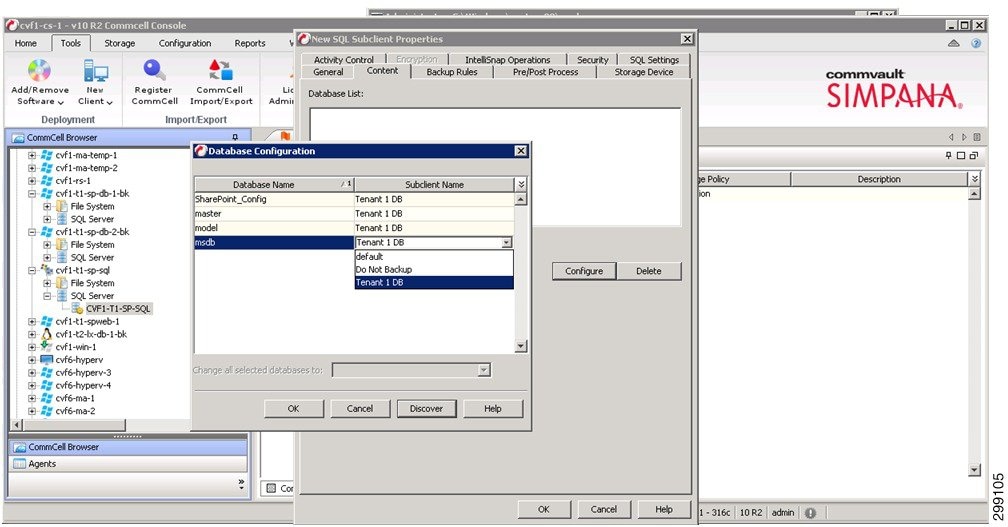
Assign this subclient to the proper Tenant Storage Policy.
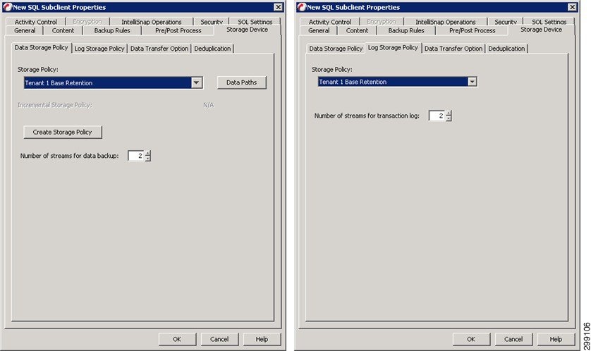
Assign this Subclient to the proper Schedule Policy and alerts can be configured against a given Schedule Policy allowing the control of who gets alerts for each different policy. Refer to the Alert configuration for Windows File System iDA, above.
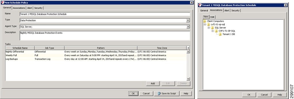
Refer to Commvault documentation for details on the Microsoft SQL Server iDA.
Oracle / Oracle RAC iDataAgent
The Oracle / Oracle RAC iDA is going to be installed on any Oracle servers, whether they are virtual or physical servers, that require database, table, and log level data protection. In this use case a single Oracle instance on a standalone server was used. Once the Client requiring protection is defined to the CommCell and then the appropriate iDA can be installed, updated and configured.
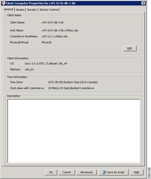
Create a new Subclient for the database being protected.
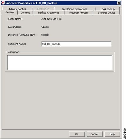
Select the Database to protect and how it will be protected.

Assign the Subclient to the proper Tenant Retention Storage Policy.
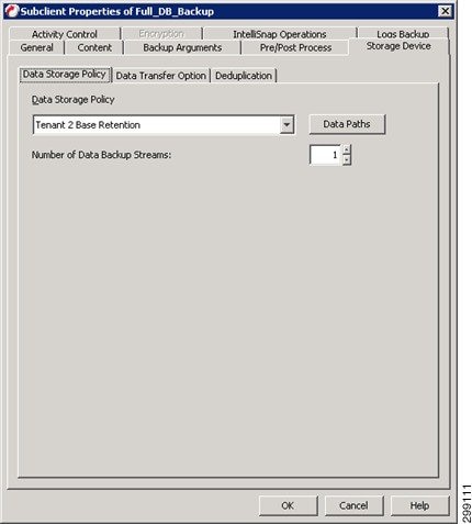
The Client is now associated to the proper Schedule Policy. The protected clients will be running an incremental backup nightly, while generating a synthetic full backup once a week. Alerts can be configured against a given Schedule Policy allowing the control of who gets alerts for each different policy. Refer to the Alert configuration for Windows File System iDA, above.
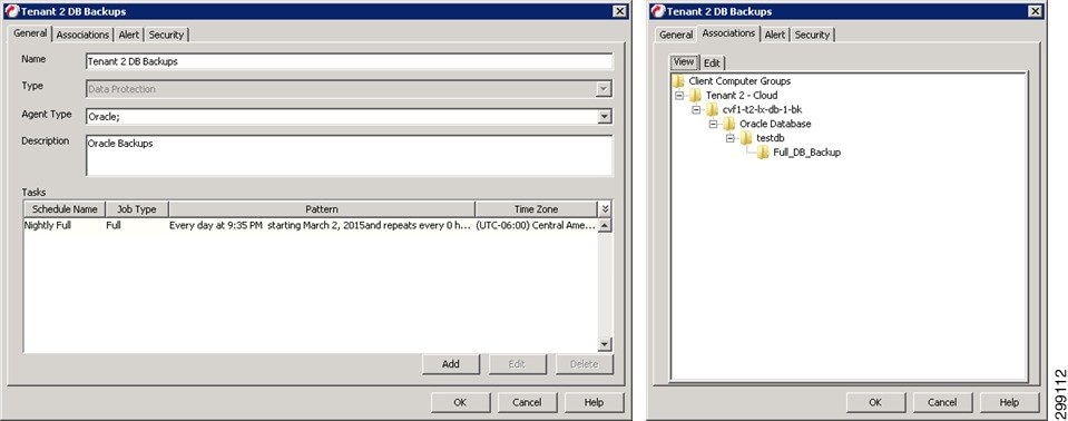
Refer to Commvault documentation for details on the Oracle RAC iDA.
Refer to Commvault documentation for details on the Oracle iDA.
Use Case 2 (Remote BaaS): Implementation Details
The second use case is Remote BaaS, where the tenant production environment is hosted at the Enterprise’s own site and backed up locally within that site and remotely to the SP1 cloud. Two tenants were created to proof this use case. In the Enterprise site, Tenant 6 was configured with OpenStack and Tenant 7 was configured with VMware. Both of these tenants were backed up locally and also into Cloud Provider site SP1.
Figure 4-38 shows the environment used to proof this use case. This use case utilizes the pre-existing SP1 environment as the primary CVLT Infrastructure, so in this use case we focused on the customer locations.. Since a local copy of the data was stored at the customer’s data center, integration of the MediaAgents was required. There was a MediaAgent pair in the Tenant 6 environment and a single MediaAgent in the Tenant 7 environment. The Tenant 6 environment was an RHEL OpenStack environment being protected, while Tenant 7 consisted of a VMWare environment. Each iDA interacted with the CommServe and local MediaAgent on a schedule basis to execute data protection jobs. The Primary copy of data was stored locally on the Local MediaAgent that executed the backup job, but then DASH (deduplicated replication) copied to a MediaAgent in the SP1 data center to provide for Disaster Recovery. Restoration of the data that was protected could be executed at either the customers’ data center or the SP1 data center.
Figure 4-38 Use Case 2 (Remote BaaS) Implementation Diagram
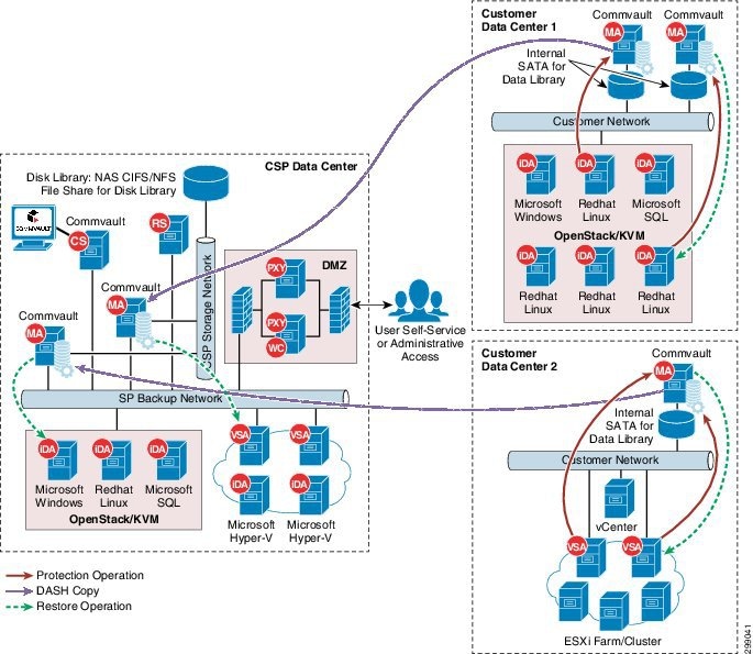
Tenant Details
Tenant 6 (RHEL OpenStack) Applications
In Tenant 6, five Linux Centos servers were used for testing purposes. There were no applications installed on these servers.
Tenant 7 (VMware) Applications
In Tenant 7, three Windows Server 2012 Standard servers were used for testing purposes. There were no applications installed on these servers.
Commvault Configuration
This section will detail how the Commvault Infrastructure and Data Protection agents were configured for this use case.
Commvault Infrastructure
This section will describe how each component of the Commvault Simpana is installed and configured.
MediaAgent Server(s)
The MediaAgent server is the data mover within the CommCell so it is the next server that needs to be built out. All connections to the actual storage, as well as the control of the deduplication is handled by the MediaAgent. The MediaAgents should be have disk volumes created for the Operating System, CVLT DDB and Index Cache. Then loaded with Windows 2012. The installation of the MediaAgent software can be pushed from the CommServe. In this case there are two MediaAgents, cvf8-ma-1, cvf8-ma-2, and cvf8-ma-3.
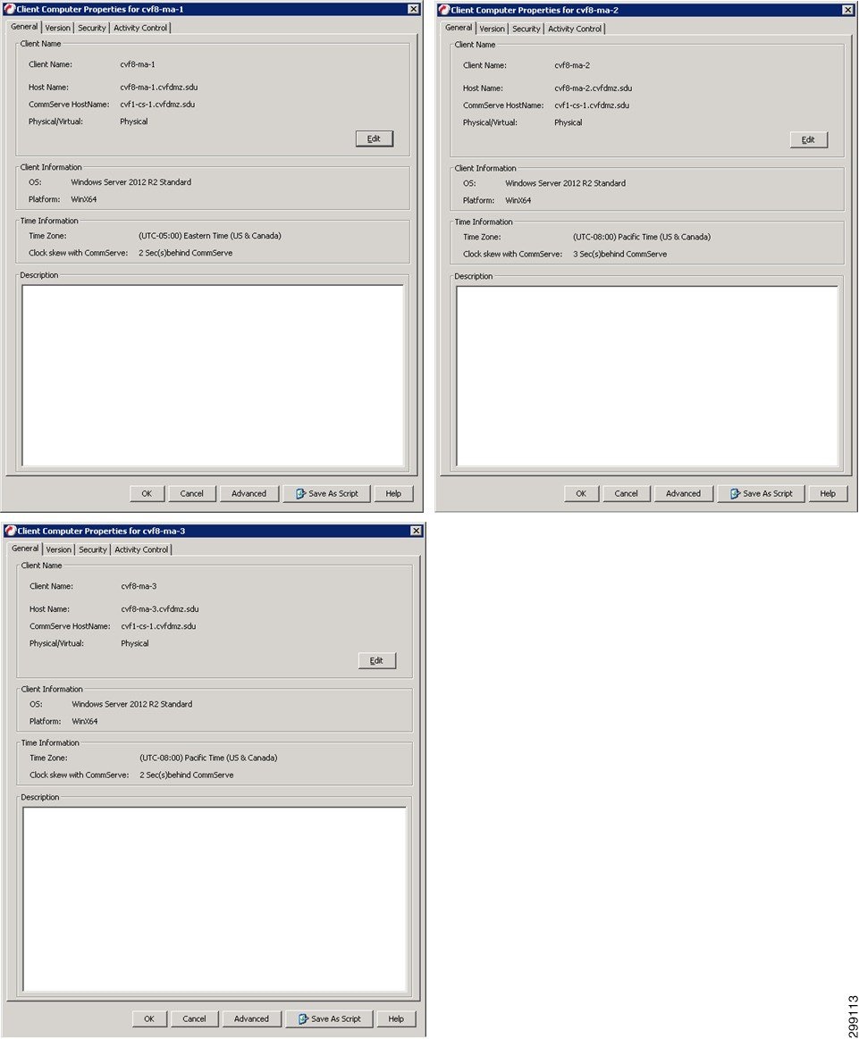
Then Disk Libraries are created from the local drives on all three MediaAgents.
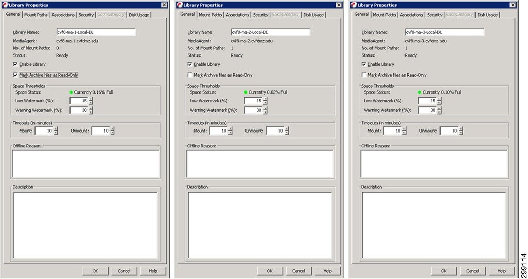
Global Partitioned DDBs are created to frontend the libraries created for CVF8-MA-1 and CVF8-MA-2 as they are working in a pair.
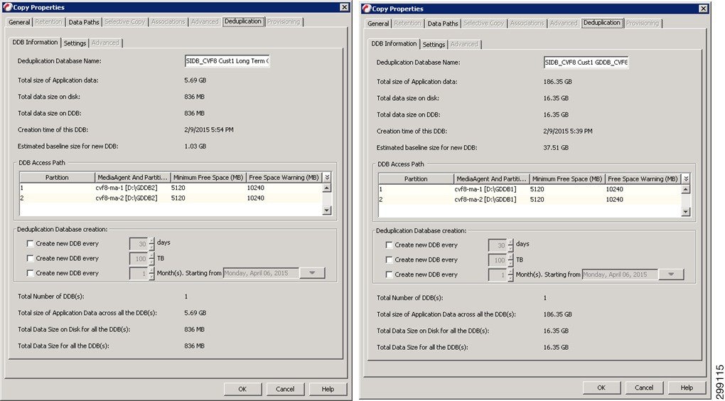
Standard DDBs are created to frontend the libraries created for CVF8-MA-3 as it is working as a standalone MediaAgent.
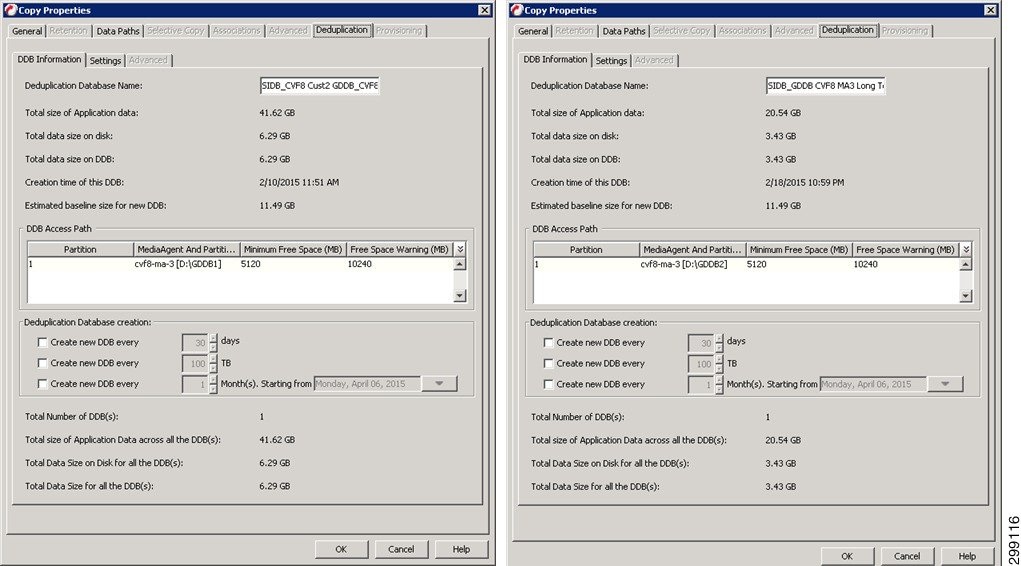
Finally the Tenant Storage Policies are configured.
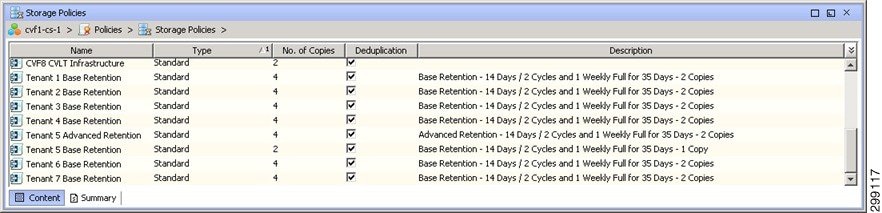
Refer to Commvault documentation for details on the MediaAgents
Virtual Server Protection
This section details how the iDataAgents were configured to provide data protection to the virtual environments in this use case.
RHEL OpenStack—Linux File System iDataAgent
The Linux File System iDA will be installed on each Linux server requiring data protection from the File System level. Once the Client requiring protection is defined to the CommCell and then the appropriate iDA can be installed, updated, and configured.
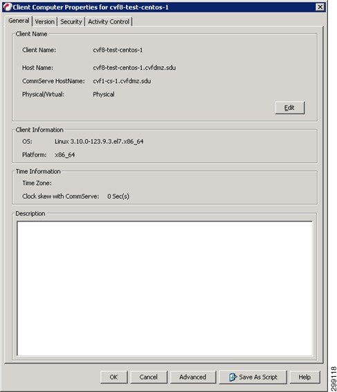
The Default File System Subclient is then assigned to the proper Tenant Retention Storage Policy.
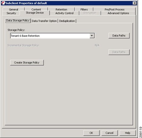
The Client is now associated to the proper Schedule Policy. The protected clients will be running an incremental backup nightly, while generating a synthetic full backup once a week and alerts can be configured against a given Schedule Policy allowing the control of who gets alerts for each different policy.
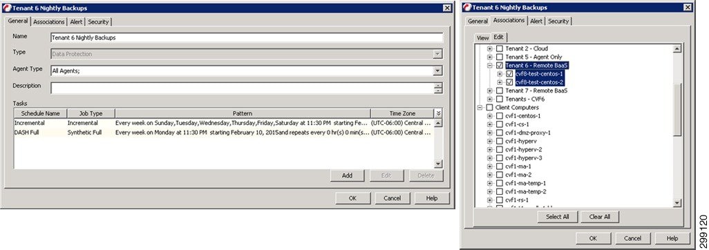
Refer to Commvault documentation for details on the Linux File System iDA.
Virtual Server iDataAgent for VMware
The VSA for VMware is installed on one or more virtual guests running Windows Server 2012. The Guests that will be used as the VSA is defined to the CommCell, the required iDAs are installed, updated and configured.
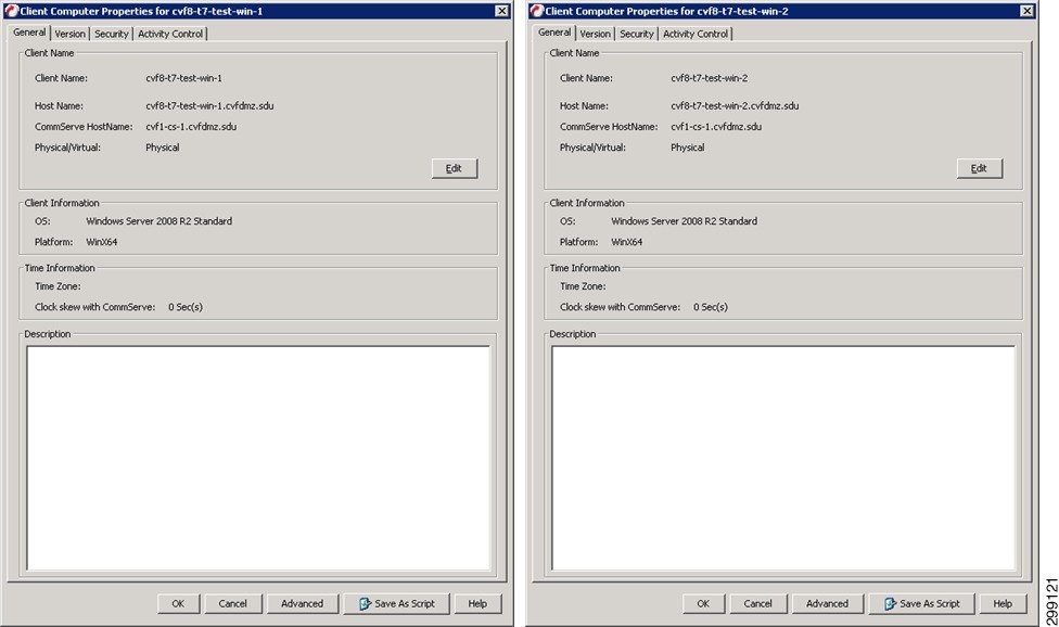
Once the VSA clients are installed, define a new VMware vCenter Client, providing credentials and designating the VSA Servers to use
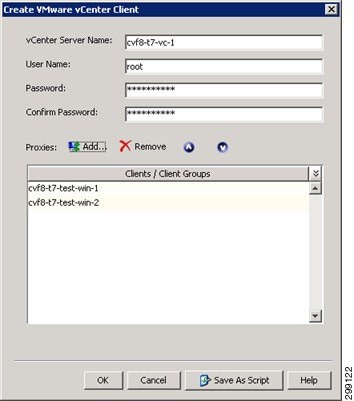
Create a subclient for the Tenant Guests and select the Guests that will be part of that Tenant.
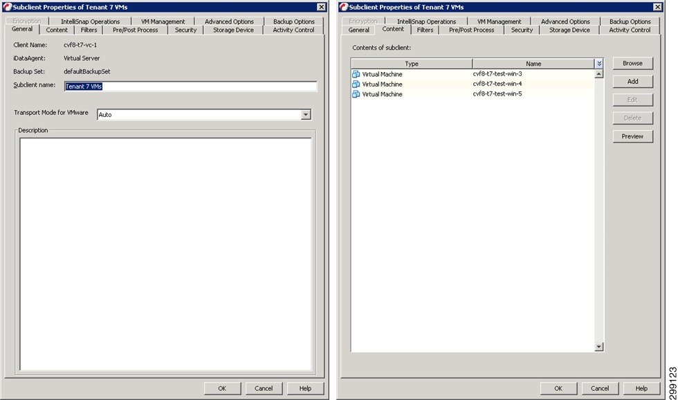
Choose the appropriate Tenant Storage Policy:
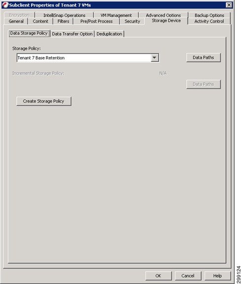
The Client is now associated to the proper Schedule Policy and alerts can be configured against a given Schedule Policy allowing the control of who gets alerts for each different policy. Refer to the Alert configuration for Windows File System iDA, above.
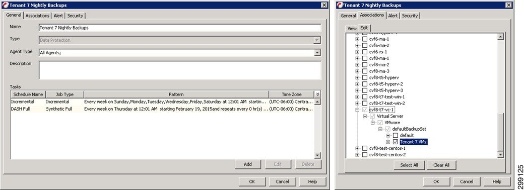
Refer to Commvault documentation for details on the Virtual Server iDA for VMware
Use Case 3 (Remote BaaS Without Local Data Retention): Implementation Details
The third use case is Remote BaaS Without Local Data Retention, where the tenant production environment is hosted at the Enterprise’s own site and backed up remotely to the SP1 cloud. One tenant was created to proof this use case. In the Enterprise site, Tenant 5 was configured with Hyper-V. The virtual machines in Tenant 5 were backed up into Cloud Provider site SP1. Commvault MediaAgents were not deployed at the Enterprise site, but Commvault agents were deployed to enable the remote protection. This use case utilizes the pre-existing SP1, and optionally the SP2, environment(s) as the primary CVLT Infrastructure, so in this use case we focused on the customer location. As this use case is not going to provide a local copy of the data within the customers’ data center, there is no further CVLT infrastructure integration that must be completed.
Figure 4-39 shows how the data flowed. Each iDA interacted with the CommServe and MediaAgent at SP1 on a schedule basis to execute data protection jobs. The Primary copy of data was stored on the MediaAgent in the SP1 data center that executed the backup job. Optionally, the data was later DASH (deduplicated replication) copied to a MediaAgent in the SP2 data center to provide a secondary copy outside of the SP1 data center. Restoration of the data that is protected could be executed at either the customer’s data center across the network, at the SP1 or the SP2 data centers.
Figure 4-39 Use Case 3 (Remote BaaS Without Local Data Retention) Implementation Topology
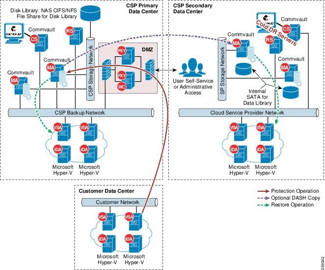
 Feedback