- Overview
- Configuring VLAN Trunking Protocol
- Configuring VLANs
- Configuring VLAN Trunks
- Configuring Asymmetric VLAN Mapping
- Configuring VMPS
- Configuring Private VLANs
- Configuring IEEE 802.1Q Tunneling
- Configuring VLAN Mapping
- Configuring Layer 2 Protocol Tunneling
- Configuring STP
- Configuring MSTP
- Configuring Optional Spanning-Tree Features
- Configuring Resilient Ethernet Protocol
- Configuring UDLD
- Configuring Voice VLAN
Configuring Layer 2 Protocol Tunneling
This chapter describes how to configure Layer 2 protocol tunneling on the Cisco Industrial Ethernet 2000U Series (IE 2000U) and Connected Grid Switches, hereafter referred to as switch.
Virtual private networks (VPNs) provide enterprise-scale connectivity on a shared infrastructure, often Ethernet-based, with the same security, prioritization, reliability, and manageability requirements of private networks. Tunneling is a feature designed for service providers who carry traffic of multiple customers across their networks and are required to maintain the VLAN and Layer 2 protocol configurations of each customer without impacting the traffic of other customers. The switch supports IEEE 802.1Q tunneling and Layer 2 protocol tunneling; IEEE 802.1Q tunneling is described in Chapter8, “Configuring IEEE 802.1Q Tunneling”

Note![]() For complete syntax and usage information for the commands used in this chapter, see the documents listed in the “Related Documents” section.
For complete syntax and usage information for the commands used in this chapter, see the documents listed in the “Related Documents” section.
Information About Layer 2 Protocol Tunneling
Customers at different sites connected across a service-provider network need to use various Layer 2 protocols to scale their topologies to include all remote sites, as well as the local sites. STP must run properly, and every VLAN should build a proper spanning tree that includes the local site and all remote sites across the service-provider network. Cisco Discovery Protocol (CDP) must discover neighboring Cisco devices from local and remote sites. VLAN Trunking Protocol (VTP) must provide consistent VLAN configuration throughout all sites in the customer network that are participating in VTP.
Note![]() CDP and STP are supported by default on NNIs and can be enabled on ENIs. However, Layer 2 protocol tunneling is supported on all ports on the switch.
CDP and STP are supported by default on NNIs and can be enabled on ENIs. However, Layer 2 protocol tunneling is supported on all ports on the switch.
When protocol tunneling is enabled, edge switches on the inbound side of the service-provider network encapsulate Layer 2 protocol packets with a special MAC address and send them across the service-provider network. Core switches in the network do not process these packets but forward them as normal packets. Layer 2 protocol data units (PDUs) for CDP, STP, or VTP cross the service-provider network and are delivered to customer switches on the outbound side of the service-provider network. Identical packets are received by all customer ports on the same VLANs with these results:
- Users on each of a customer’s sites can properly run STP, and every VLAN can build a correct spanning tree based on parameters from all sites and not just from the local site.
- CDP discovers and shows information about the other Cisco devices connected through the service-provider network.
- VTP provides consistent VLAN configuration throughout the customer network, propagating to all switches through the service provider that support VTP.
Note![]() To provide interoperability with third-party vendors, you can use the Layer 2 protocol-tunnel bypass feature. Bypass mode transparently forwards control PDUs to vendor switches that have different ways of controlling protocol tunneling. You implement bypass mode by enabling Layer 2 protocol tunneling on the egress trunk port. When Layer 2 protocol tunneling is enabled on the trunk port, the encapsulated tunnel MAC address is removed and the protocol packets have their normal MAC address.
To provide interoperability with third-party vendors, you can use the Layer 2 protocol-tunnel bypass feature. Bypass mode transparently forwards control PDUs to vendor switches that have different ways of controlling protocol tunneling. You implement bypass mode by enabling Layer 2 protocol tunneling on the egress trunk port. When Layer 2 protocol tunneling is enabled on the trunk port, the encapsulated tunnel MAC address is removed and the protocol packets have their normal MAC address.
Layer 2 protocol tunneling can be used independently or can enhance 802.1Q tunneling. If protocol tunneling is not enabled on 802.1Q tunneling ports, remote switches at the receiving end of the service-provider network do not receive the PDUs and cannot properly run STP, CDP, and VTP. When protocol tunneling is enabled, Layer 2 protocols within each customer’s network are totally separate from those running within the service-provider network. Customer switches on different sites that send traffic through the service-provider network with 802.1Q tunneling achieve complete knowledge of the customer’s VLAN. If 802.1Q tunneling is not used, you can still enable Layer 2 protocol tunneling by connecting to the customer switch through access or trunk ports and enabling tunneling on the service-provider access or trunk port.
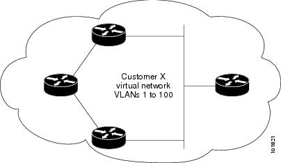
For example, in Figure 10-1, Customer X has four switches in the same VLAN, that are connected through the service-provider network. If the network does not tunnel PDUs, switches on the far ends of the network cannot properly run STP, CDP, and VTP. For example, STP for a VLAN on a switch in Customer X, Site 1, will build a spanning tree on the switches at that site without considering convergence parameters based on Customer X’s switch in Site 2. This could result in the topology shown in Figure 10-2.
Figure 10-1 Layer 2 Protocol Tunneling
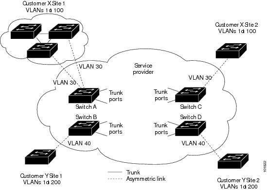
Figure 10-2 Layer 2 Network Topology without Proper Convergence
In an SP network, you can use Layer 2 protocol tunneling to enhance the creation of EtherChannels by emulating a point-to-point network topology. When you enable protocol tunneling (PAgP or LACP) on the SP switch, remote customer switches receive the PDUs and can negotiate the automatic creation of EtherChannels.
For example, in Figure 10-3, Customer A has two switches in the same VLAN that are connected through the SP network. When the network tunnels PDUs, switches on the far ends of the network can negotiate the automatic creation of EtherChannels without needing dedicated lines. See the “Configuring Layer 2 Tunneling for EtherChannels” section for instructions.
Figure 10-3 Layer 2 Protocol Tunneling for EtherChannels

Prerequisites
- Be familiar with the information in the “Information About Layer 2 Protocol Tunneling” section and “Guidelines and Limitations” section.
- Ensure that your network strategy and planning for your network are complete.
Guidelines and Limitations
These are some configuration guidelines and operating characteristics of Layer 2 protocol tunneling:
- The switch supports tunneling of CDP, STP, including multiple STP (MSTP), and VTP. Protocol tunneling is disabled by default but can be enabled for the individual protocols on 802.1Q tunnel ports, access ports. or trunk ports.
- The edge switches on the outbound side of the service-provider network restore the proper Layer 2 protocol and MAC address information and forward the packets to all Layer 2 protocol-enabled tunnel, access, and trunk ports in the same metro VLAN.
- For interoperability with third-party vendor switches, the switch supports a Layer 2 protocol-tunnel bypass feature. Bypass mode transparently forwards control PDUs to vendor switches that have different ways of controlling protocol tunneling.When Layer 2 protocol tunneling is enabled on ingress ports on a switch, egress trunk ports forward the tunneled packets with a special encapsulation. If you also enable Layer 2 protocol tunneling on the egress trunk port, this behavior is bypassed, and the switch forwards control PDUs without any processing or modification.
- The switch supports PAgP, LACP, and UDLD tunneling for emulated point-to-point network topologies. Protocol tunneling is disabled by default but can be enabled for the individual protocols on 802.1Q tunnel ports, access ports, or trunk ports.
- If you enable PAgP or LACP tunneling, we recommend that you also enable UDLD on the interface for faster link-failure detection.
- Loopback detection is not supported on Layer 2 protocol tunneling of PAgP, LACP, or UDLD packets.
- EtherChannel port groups are compatible with tunnel ports when the 802.1Q configuration is consistent within an EtherChannel port group.
- If an encapsulated PDU (with the proprietary destination MAC address) is received from a tunnel port or access or trunk port with Layer 2 tunneling enabled, the tunnel port is shut down to prevent loops. The port also shuts down when a configured shutdown threshold for the protocol is reached. You can manually re-enable the port (by entering a shutdown and a no shutdown command sequence). If errdisable recovery is enabled, the operation is retried after a specified time interval.
- Only decapsulated PDUs are forwarded to the customer network. The spanning-tree instance running on the service-provider network does not forward BPDUs to tunnel ports. CDP packets are not forwarded from tunnel ports.
- When protocol tunneling is enabled on an interface, you can set a per-protocol, per-port, shutdown threshold for the PDUs generated by the customer network. If the limit is exceeded, the port shuts down. You can also limit BPDU rate by using QoS ACLs and policy maps on a tunnel port.
- When protocol tunneling is enabled on an interface, you can set a per-protocol, per-port, drop threshold for the PDUs generated by the customer network. If the limit is exceeded, the port drops PDUs until the rate at which it receives them is below the drop threshold.
- Because tunneled PDUs (especially STP BPDUs) must be delivered to all remote sites so that the customer virtual network operates properly, you can give PDUs higher priority within the service-provider network than data packets received from the same tunnel port. By default, the PDUs use the same CoS value as data packets.
Default Settings
Configuring Layer 2 Protocol Tunneling
You can enable Layer 2 protocol tunneling (by protocol) on the ports that are connected to the customer in the edge switches of the service-provider network. The service-provider edge switches connected to the customer switch perform the tunneling process. Edge-switch tunnel ports are connected to customer 802.1Q trunk ports. Edge-switch access ports are connected to customer access ports. The edge switches connected to the customer switch perform the tunneling process.
You can enable Layer 2 protocol tunneling on ports that are configured as access ports, tunnel ports, or trunk ports. The switch supports Layer 2 protocol tunneling for CDP, STP, and VTP. For emulated point-to-point network topologies, it also supports PAgP, LACP, and UDLD protocols. The switch does not support Layer 2 protocol tunneling for LLDP.

When the Layer 2 PDUs that entered the service-provider inbound edge switch through a Layer 2 protocol-enabled port exit through the trunk port into the service-provider network, the switch overwrites the customer PDU-destination MAC address with a well-known Cisco proprietary multicast address (01-00-0c-cd-cd-d0). If 802.1Q tunneling is enabled, packets are also double-tagged; the outer tag is the customer metro tag, and the inner tag is the customer’s VLAN tag. The core switches ignore the inner tags and forward the packet to all trunk ports in the same metro VLAN. The edge switches on the outbound side restore the proper Layer 2 protocol and MAC address information and forward the packets to all Layer 2 protocol-enabled access ports, tunnel ports, and trunk ports in the same metro VLAN. Therefore, the Layer 2 PDUs remain intact and are delivered across the service-provider infrastructure to the other side of the customer network.
See Figure 10-1, with Customer X and Customer Y in access VLANs 30 and 40, respectively. Asymmetric links connect the customers in Site 1 to edge switches in the service-provider network. The Layer 2 PDUs (for example, BPDUs) coming into Switch B from Customer Y in Site 1 are forwarded to the infrastructure as double-tagged packets with the well-known MAC address as the destination MAC address. These double-tagged packets have the metro VLAN tag of 40, as well as an inner VLAN tag (for example, VLAN 100). When the double-tagged packets enter Switch D, the outer VLAN tag 40 is removed, the well-known MAC address is replaced with the respective Layer 2 protocol MAC address, and the packet is sent to Customer Y on Site 2 as a single-tagged frame in VLAN 100.
You can also enable Layer 2 protocol tunneling on access ports on the edge switch connected to access or trunk ports on the customer switch. In this case, the encapsulation and decapsulation process is the same as described in the previous paragraph, except that the packets are not double-tagged in the service-provider network. The single tag is the customer-specific access VLAN tag.
This section includes the following topics:
Configuring a Port for Layer 2 Protocol Tunneling
BEFORE YOU BEGIN
Review the “Guidelines and Limitations” section.
DETAILED STEPS
Use the no l2protocol-tunnel [ cdp | stp | vtp ] interface configuration command to disable protocol tunneling for one of the Layer 2 protocols or for all three. Use the no l2protocol-tunnel shutdown-threshold [ cdp | stp | vtp ] and the no l2protocol-tunnel drop-threshold [ cdp | stp | vtp ] commands to return the shutdown and drop thresholds to the default settings.
EXAMPLE
This example shows how to configure Layer 2 protocol tunneling for CDP, STP, and VTP and to verify the configuration.
Configuring Layer 2 Tunneling for EtherChannels
To configure Layer 2 point-to-point tunneling to facilitate the creation of EtherChannels, you need to configure both the SP edge switch and the customer switch. (See Figure 10-3.)
Configuring the SP Edge Switch
BEFORE YOU BEGIN
Review the “Guidelines and Limitations” section.
DETAILED STEPS
Use the no l2protocol-tunnel [ point-to-point [ pagp | lacp | udld ]] interface configuration command to disable point-to-point protocol tunneling for one of the Layer 2 protocols or for all three. Use the no l2protocol-tunnel shutdown-threshold [ point-to-point [ pagp | lacp | udld ]] and the no l2protocol-tunnel drop-threshold [ [ point-to-point [ pagp | lacp | udld ]] commands to return the shutdown and drop thresholds to the default settings.
EXAMPLE
This example shows how to configure the SP edge switch 1 and edge switch 2. VLANs 17, 18, 19, and 20 are the access VLANs, Gigabit Ethernet interfaces 1 and 2 are point-to-point tunnel ports with PAgP and UDLD enabled, the drop threshold is 1000, and Fast Ethernet interface 3 is a trunk port.
SP edge switch 1 configuration:
SP edge switch 2 configuration:
Configuring the Customer Switch
For EtherChannels, you need to configure both the SP edge switches and the customer switches for Layer 2 protocol tunneling. (See Figure 10-3.)
BEFORE YOU BEGIN
Configure the SP edge switch as described in the Configuring the SP Edge Switch.
DETAILED STEPS
|
|
|
|
|---|---|---|
Enter the interface configuration mode. This should be the customer switch port. |
||
Enable the port, if necessary. By default, UNIs and ENIs are disabled and NNIs are enabled. |
||
Assign the interface to a channel group, and specify desirable for the PAgP mode if the interface is an NNI or ENI. For more information about configuring EtherChannels, see the “Configuring EtherChannels and Link State Tracking” chapter in the High Availability and Redundancy Software Configuration Guide for Cisco IE 2000U and Connected Grid Switches. |
||
Display the Layer 2 tunnel ports on the switch, including the protocols configured, the thresholds, and the counters. |
||
Use the no switchport mode trunk, the no udld enable, and the no channel group channel-group-number mode desirable interface configuration commands to return the interface to the default settings.
EXAMPLE
This example shows how to configure the customer switch at Site 1. Fast Ethernet interfaces 1, 2, 3, and 4 are set for 802.1Q trunking, UDLD is enabled, EtherChannel group 1 is enabled, and the port channel is shut down and then enabled to activate the EtherChannel configuration.
Verifying Configuration
Configuration Example
This example shows how to configure Layer 2 protocol tunneling for CDP, STP, and VTP and to verify the configuration.
This example shows how to configure the SP edge switch 1 and edge switch 2. VLANs 17, 18, 19, and 20 are the access VLANs, Gigabit Ethernet interfaces 1 and 2 are point-to-point tunnel ports with PAgP and UDLD enabled, the drop threshold is 1000, and Fast Ethernet interface 3 is a trunk port.
SP edge switch 1 configuration:
SP edge switch 2 configuration:
This example shows how to configure the customer switch at Site 1. Fast Ethernet interfaces 1, 2, 3, and 4 are set for 802.1Q trunking, UDLD is enabled, EtherChannel group 1 is enabled, and the port channel is shut down and then enabled to activate the EtherChannel configuration.
Related Documents
Feature History
|
|
|
|---|---|
 Feedback