- Overview
- Configuring VLAN Trunking Protocol
- Configuring VLANs
- Configuring VLAN Trunks
- Configuring Asymmetric VLAN Mapping
- Configuring VMPS
- Configuring Private VLANs
- Configuring IEEE 802.1Q Tunneling
- Configuring VLAN Mapping
- Configuring Layer 2 Protocol Tunneling
- Configuring STP
- Configuring MSTP
- Configuring Optional Spanning-Tree Features
- Configuring Resilient Ethernet Protocol
- Configuring UDLD
- Configuring Voice VLAN
Layer 2 Switching Software Configuration Guide for Cisco IE 2000U and Connected Grid Switches
Bias-Free Language
The documentation set for this product strives to use bias-free language. For the purposes of this documentation set, bias-free is defined as language that does not imply discrimination based on age, disability, gender, racial identity, ethnic identity, sexual orientation, socioeconomic status, and intersectionality. Exceptions may be present in the documentation due to language that is hardcoded in the user interfaces of the product software, language used based on RFP documentation, or language that is used by a referenced third-party product. Learn more about how Cisco is using Inclusive Language.
- Updated:
- May 16, 2013
Chapter: Configuring VLAN Trunks
Configuring VLAN Trunks
This chapter provides the following information about configuring VLAN trunks on the Cisco Industrial Ethernet 2000U Series (IE 2000U) and Connected Grid Switches, hereafter referred to as switch :
- Information About Trunks
- Prerequisites
- Guidelines and Limitations
- Default Settings
- Configuring VLAN Trunks
- Verifying Configuration
- Configuration Example
- Related Documents
- Feature History

Note![]() For complete syntax and usage information for the commands used in this chapter, see the documents listed in the “Related Documents” section.
For complete syntax and usage information for the commands used in this chapter, see the documents listed in the “Related Documents” section.
Information About Trunks
A trunk is a point-to-point link between one or more Ethernet switch interfaces and another networking device such as a router or a switch. Ethernet trunks carry the traffic of multiple VLANs over a single link, and you can extend the VLANs across an entire network. The switch supports the 802.1Q industry-standard trunking encapsulation.
You can configure a trunk on a single Ethernet interface or on an EtherChannel bundle. For more information about EtherChannels, see the “Configuring EtherChannels and Link State Tracking” chapter in the High Availability and Redundancy Software Configuration Guide for Cisco IE 2000U and Connected Grid Switches.
Ethernet interfaces support different trunking modes (see Table 4-1 ). You can set an interface as trunking or nontrunking.
- If you do not intend to trunk across links, use the switchport mode a ccess interface configuration command to disable trunking.
- To enable trunking, use the switchport mode trunk interface configuration command to change the interface to a trunk.
|
|
|
|---|---|
Puts the interface (access port) into permanent nontrunking mode and negotiates to convert the link into a nontrunk link. The interface becomes a nontrunk interface regardless of whether or not the neighboring interface is a trunk interface. This is the default mode. |
|
Puts the interface into permanent trunking mode and negotiates to convert the neighboring link into a trunk link. The interface becomes a trunk interface even if the neighboring interface is not a trunk interface. |
|
Configures the interface as a tunnel (nontrunking) port to be connected in an asymmetric link with an 802.1Q trunk port. The 802.1Q tunneling is used to maintain customer VLAN integrity across a service provider network. See “Configuring Layer 2 Protocol Tunneling,” for more information on tunnel ports. |
|
Configure the interface as a private VLAN host or promiscuous port (only NNIs can be configured as promiscuous ports). For information about private VLANs, see Chapter7, “Configuring Private VLANs” |
Prerequisites
- Be familiar with the information in the “Information About Trunks” section and “Guidelines and Limitations” section.
- Ensure that your network strategy and planning for your network are complete.
Guidelines and Limitations
The 802.1Q trunks impose these limitations on the trunking strategy for a network:
- In a network of Cisco switches connected through 802.1Q trunks, the switches maintain one spanning-tree instance for each VLAN allowed on the trunks. Non-Cisco devices might support one spanning-tree instance for all VLANs.
When you connect a Cisco switch to a non-Cisco device through an 802.1Q trunk, the Cisco switch combines the spanning-tree instance of the VLAN of the trunk with the spanning-tree instance of the non-Cisco 802.1Q switch. However, spanning-tree information for each VLAN is maintained by Cisco switches separated by a cloud of non-Cisco 802.1Q switches. The non-Cisco 802.1Q cloud separating the Cisco switches is treated as a single trunk link between the switches.
- Make sure that the native VLAN for an 802.1Q trunk is the same on both ends of the trunk link. If the native VLAN on one end of the trunk is different from the native VLAN on the other end, spanning-tree loops might result.
- Disabling spanning tree on the native VLAN of an 802.1Q trunk without disabling spanning tree on every VLAN in the network can potentially cause spanning-tree loops. We recommend that you leave spanning tree enabled on the native VLAN of an 802.1Q trunk or disable spanning tree on every VLAN in the network. Make sure that your network is loop-free before disabling spanning tree.
Interaction with Other Features
Trunking interacts with other features in these ways:
- A trunk port cannot be a secure port.
- A trunk port cannot be a tunnel port.
- Trunk ports can be grouped into EtherChannel port groups, but all trunks in the group must have the same configuration. When a group is first created, all ports follow the parameters set for the first port to be added to the group. If you change the configuration of one of these parameters, the switch propagates the setting that you entered to all ports in the group:
–![]() STP port priority for each VLAN.
STP port priority for each VLAN.
Note![]() STP is supported by default on NNIs, but must be enabled on ENIs. STP is not supported on UNIs.
STP is supported by default on NNIs, but must be enabled on ENIs. STP is not supported on UNIs.
–![]() trunk status: if one port in a port group ceases to be a trunk, all ports cease to be trunks.
trunk status: if one port in a port group ceases to be a trunk, all ports cease to be trunks.
Default Settings
The following table shows the default Layer 2 Ethernet interface VLAN configuration.
|
|
|
|---|---|
Configuring VLAN Trunks
This section includes the following topics:
- Configuring a Trunk Port
- Defining the Allowed VLANs on a Trunk
- Configuring the Native VLAN for Untagged Traffic
- Configuring Trunk Ports for Load Sharing
Configuring a Trunk Port
Follow this procedure to configure a a port as an 802.1Q trunk port.
BEFORE YOU BEGIN
Review the “Guidelines and Limitations” section.
DETAILED STEPS
To return an interface to its default configuration, use the default interface interface-id interface configuration command. To reset all trunking characteristics of a trunking interface to the defaults, use the no switchport trunk interface configuration command. To disable trunking, use the switchport mode access interface configuration command to configure the port as a static-access port.
EXAMPLE
This example shows how to configure a port as an 802.1Q trunk with VLAN 33 as the native VLAN:
Defining the Allowed VLANs on a Trunk
By default, a trunk port sends traffic to and receives traffic from all VLANs. All VLAN IDs, 1 to 4094, are allowed on each trunk. However, you can remove VLANs from the allowed list, preventing traffic from those VLANs from passing over the trunk. To restrict the traffic a trunk carries, use the switchport trunk allowed vlan remove vlan-list interface configuration command to remove specific VLANs from the allowed list.
Note![]() VLAN 1 is the default VLAN on all trunk ports in all Cisco switches, and it has previously been a requirement that VLAN 1 always be enabled on every trunk link. The VLAN 1 minimization feature allows you to disable VLAN 1 on any individual VLAN trunk link so that no user traffic (including spanning-tree advertisements) is sent or received on VLAN 1. You do this by removing VLAN 1 from the allowed VLAN list.
VLAN 1 is the default VLAN on all trunk ports in all Cisco switches, and it has previously been a requirement that VLAN 1 always be enabled on every trunk link. The VLAN 1 minimization feature allows you to disable VLAN 1 on any individual VLAN trunk link so that no user traffic (including spanning-tree advertisements) is sent or received on VLAN 1. You do this by removing VLAN 1 from the allowed VLAN list.
To reduce the risk of spanning-tree loops or storms, you can disable VLAN 1 on any individual VLAN trunk port by removing VLAN 1 from the allowed list. When you remove VLAN 1 from a trunk port, the interface continues to send and receive management traffic, for example, Cisco Discovery Protocol (CDP), Port Aggregation Protocol (PAgP), and Link Aggregation Control Protocol (LACP) in VLAN 1.
If a trunk port with VLAN 1 disabled is converted to a nontrunk port, it is added to the access VLAN. If the access VLAN is set to 1, the port is added to VLAN 1, regardless of the switchport trunk allowed setting. The same is true for any VLAN that has been disabled on the port.
A trunk port can become a member of a VLAN if the VLAN is enabled and if the VLAN is in the allowed list for the port.
BEFORE YOU BEGIN
Review the “Guidelines and Limitations” section.
DETAILED STEPS
Beginning in privileged EXEC mode, follow these steps to modify the allowed list of an IEEE 802.1Q trunk:
To return to the default allowed VLAN list of all VLANs, use the no switchport trunk allowed vlan interface configuration command.
EXAMPLE
This example shows how to remove VLAN 2 from the allowed VLAN list on a port:
Configuring the Native VLAN for Untagged Traffic
A trunk port configured with 802.1Q tagging can receive both tagged and untagged traffic. By default, the switch forwards untagged traffic in the native VLAN configured for the port. The native VLAN is VLAN 1 by default. If a packet has a VLAN ID that is the same as the sending port native VLAN ID, the packet is sent untagged; otherwise, the switch sends the packet with a tag.
Note![]() The native VLAN can be assigned any VLAN ID.
The native VLAN can be assigned any VLAN ID.
For information about 802.1Q configuration issues, see the “Guidelines and Limitations” section.
BEFORE YOU BEGIN
Configure a trunk port as described in the Configuring a Trunk Port.
DETAILED STEPS
Beginning in privileged EXEC mode, follow these steps to configure the native VLAN on an IEEE 802.1Q trunk:
To return to the default native VLAN, VLAN 1, use the no switchport trunk native vlan interface configuration command.
EXAMPLE
This example configures VLAN 100 as the native VLAN for the trunk port:
Configuring Trunk Ports for Load Sharing
Load sharing divides the bandwidth supplied by parallel trunks that connect switches. To avoid loops, STP normally blocks all but one parallel link between switches. Using load sharing, you divide the traffic between the links according to the VLAN to which the traffic belongs.
You configure load sharing on trunk ports that have STP enabled by using STP port priorities or STP path costs. For load sharing using STP port priorities, both load-sharing links must be connected to the same switch. For load sharing using STP path costs, each load-sharing link can be connected to the same switch or to two different switches. For more information about STP, see Chapter11, “Configuring STP”
Load Sharing Using STP Port Priorities
When two ports on the same switch form a loop, the switch uses the STP port priority to decide which port is enabled and which port is in a blocking state. You can set the priorities on a parallel STP trunk port so that the port carries all the traffic for a given VLAN. The trunk port with the higher priority (lower values) for a VLAN is forwarding traffic for that VLAN. The trunk port with the lower priority (higher values) for the same VLAN remains in a blocking state for that VLAN. One trunk port sends or receives all traffic for the VLAN.
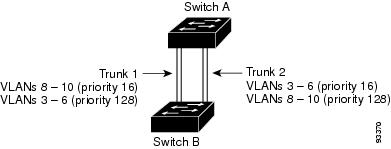
Figure 4-1 shows two trunks connecting supported switches. In this example, the switches are configured as follows:
- VLANs 8 through 10 are assigned a port priority of 16 on Trunk 1.
- VLANs 3 through 6 retain the default port priority of 128 on Trunk 1.
- VLANs 3 through 6 are assigned a port priority of 16 on Trunk 2.
- VLANs 8 through 10 retain the default port priority of 128 on Trunk 2.
In this way, Trunk 1 carries traffic for VLANs 8 through 10, and Trunk 2 carries traffic for VLANs 3 through 6. If the active trunk fails, the trunk with the lower priority takes over and carries the traffic for all of the VLANs. No duplication of traffic occurs over any trunk port.
Figure 4-1 Load Sharing by Using STP Port Priorities
Follow this procedure on Switch A to configure the network shown in Figure 4-1. Note that you can use any interface numbers; those shown are examples only.
BEFORE YOU BEGIN
If you configure the port as an ENI, you must also enable STP on the port by entering the spanning-tree interface configuration command.
DETAILED STEPS
Follow the same steps on Switch B to configure the trunk port for Trunk 1 with a spanning-tree port priority of 16 for VLANs 8 through 10, and configure the trunk port for Trunk 2 with a spanning-tree port priority of 16 for VLANs 3 through 6.
EXAMPLE
This example configures Switch A for the network shown in Figure 4-1.
Load Sharing Using STP Path Cost
You can configure parallel trunks to share VLAN traffic by setting different path costs on a trunk and associating the path costs with different sets of VLANs, blocking different ports for different VLANs. You can assign lower cost values to interfaces that you want selected first and higher cost values that you want selected last. (See the “Configuring Path Cost” section.) The VLANs keep the traffic separate and maintain redundancy in the event of a lost link.
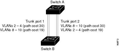
In Figure 4-2, Trunk ports 1 and 2 are configured as 100Base-T ports. These VLAN path costs are assigned:
- VLANs 2 through 4 are assigned a path cost of 30 on Trunk port 1.
- VLANs 8 through 10 retain the default 100Base-T path cost on Trunk port 1 of 19.
- VLANs 8 through 10 are assigned a path cost of 30 on Trunk port 2.
- VLANs 2 through 4 retain the default 100Base-T path cost on Trunk port 2 of 19.
Figure 4-2 Load-Sharing Trunks with Traffic Distributed by Path Cost
Follow this procedure to configure the network shown in Figure 4-2.
BEFORE YOU BEGIN
If you configure the port as an ENI, you must also enable STP on the port by entering the spanning-tree interface configuration command.
DETAILED STEPS
Follow the same steps on Switch B to configure the trunk port for Trunk 1 with a path cost of 30 for VLANs 2 through 4, and configure the trunk port for Trunk 2 with a path cost of 30 for VLANs 8 through 10.
EXAMPLE
This examples configures Switch A for the network shown in Figure 4-2.
Verifying Configuration
|
|
|
|---|---|
Configuration Example
This example shows how to configure a port as an 802.1Q trunk with VLAN 33 as the native VLAN:
This example shows how to remove VLAN 2 from the allowed VLAN list on a port:
This example configures VLAN 100 as the native VLAN for the trunk port:
This example configures Switch A for the network shown in Figure 4-1.
This examples configures Switch A for the network shown in Figure 4-2.
Related Documents
Feature History
|
|
|
|---|---|
 Feedback