The documentation set for this product strives to use bias-free language. For the purposes of this documentation set, bias-free is defined as language that does not imply discrimination based on age, disability, gender, racial identity, ethnic identity, sexual orientation, socioeconomic status, and intersectionality. Exceptions may be present in the documentation due to language that is hardcoded in the user interfaces of the product software, language used based on RFP documentation, or language that is used by a referenced third-party product. Learn more about how Cisco is using Inclusive Language.
This document includes information of components that may not be included in the Cloud Services Platform (CSP) 5200 such as,
DC Power supplies, and NVMe drives.
The CSP 5200 platform currently supports:
Small form-factor (SFF) drives, with 10-drive backplane. Supports up to 10 2.5 in. (6.35 cm) SAS/SATA drives. Although there
are ten disk drive-bays, only eight are used. This usage is because the CSP platform uses RAID 10, which uses disks in multiple
of fours.
External Features
This topic shows the external features of the server versions.
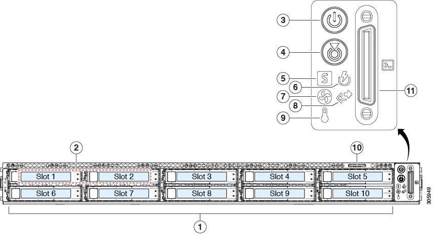
Cisco CSP 5200 Server (SFF Drives) Front Panel Features
The following figure shows the front panel features of the small form-factor drive versions of the server.
Modular LAN-on-motherboard (mLOM) card bay (x16 PCIe lane)
7
Rear unit identification button/LED
2
USB 3.0 ports (two)
8
Power supplies (two, redundant as 1+1)
3
Dual 1-Gb/10-Gb Ethernet ports (LAN1 and LAN2)
The dual LAN ports can support 1 Gbps and 10 Gbps, depending on the link partner capability.
9
PCIe riser 2/slot 2 (x16 lane)
Includes PCIe cable connectors for front-loading NVMe SSDs (x8 lane)
4
VGA video port (DB-15 connector)
10
PCIe riser 1/slot 1 (x16 lane)
5
1-Gb Ethernet dedicated management port
11
Threaded holes for dual-hole grounding lug
6
Serial port (RJ-45 connector)
-
Serviceable Component Locations
This topic shows the locations of the field-replaceable components and service-related items. The view in the following figure
shows the Cisco CSP 5200 with the top cover removed.
Front-loading drive bays 1–10 support SAS/SATA drives.
10
Power supplies (hot-swappable when redundant as 1+1)
2
Cooling fan modules (seven, hot-swappable)
11
Trusted platform module (TPM) socket on motherboard (not visible in this view)
3
Supercap unit mounting bracket (RAID backup)
12
PCIe riser 2/slot 2 (half-height, x16 lane)
4
DIMM sockets on motherboard (12 per CPU)
13
PCIe riser 1/slot 1 (full-height, x16 lane)
Includes socket for Micro-SD card
5
CPUs and heatsinks (up to two)
14
Modular LOM (mLOM) card bay on chassis floor (x16 PCIe lane), not visible in this view
6
Mini storage module socket
Supports an SD card module with two SD card slots.
15
Modular RAID (mRAID) riser supports:
Hardware RAID controller card
7
Chassis intrusion switch (optional)
16
PCIe cable connectors for front-loading NVMe SSDs on PCIe riser 2
8
Internal USB 3.0 port on motherboard
17
Micro-SD card socket on PCIe riser 1
9
RTC battery, vertical socket
-
The Technical Specifications Sheets for all versions of this server, which include supported component part numbers, are at
Cisco CSP 5000 Servers Technical Specifications Sheets (scroll down to Technical Specifications).
Summary of Server Features
The following table lists a summary of server features.
Feature
Description
Chassis
One rack-unit (1RU) chassis
Central Processor
Up to two CPUs from the Intel Xeon Processor Scalable Family. This includes CPUs from the following series:
Intel Xeon Silver 4XXX Processors
Intel Xeon Gold 5XXX Processors
Intel Xeon Gold 6XXX Processors
Intel Xeon Platinum 8XXX Processors
Memory
24 DDR4 DIMM sockets on the motherboard (12 each CPU)
Depending on your Cisco IMC settings, Cisco IMC can be accessed through the 1-Gb dedicated management port, the 1-Gb/10-Gb
Ethernet LAN ports, or a Cisco virtual interface card.
Network and management I/O
Rear panel:
One 1-Gb Ethernet dedicated management port (RJ-45 connector)
Two 1-Gb/10-Gb BASE-T Ethernet LAN ports (RJ-45 connectors)
The dual LAN ports can support 1 Gbps and 10 Gbps, depending on the link partner capability.
One RS-232 serial port (RJ-45 connector)
One VGA video connector port (DB-15 connector)
Two USB 3.0 ports
Front panel:
One front-panel keyboard/video/mouse (KVM) connector that is used with the KVM cable, which provides two USB 2.0, one VGA,
and one DB-9 serial connector.
Modular LOM
One dedicated socket (x16 PCIe lane) that can be used to add an mLOM card for additional rear-panel connectivity.
WoL
The two 1-Gb/10-Gb BASE-T Ethernet LAN ports support the wake-on-LAN (WoL) standard.
Power
Two power supplies, redundant as 1+1:
AC power supplies 770 W AC each
ACPI
The advanced configuration and power interface (ACPI) 4.0 standard is supported.
Cooling
Seven hot-swappable fan modules for front-to-rear cooling.
PCIe I/O
Two horizontal PCIe expansion slots on a PCIe riser assembly.


 Feedback