Overview

Overview

This document includes information of components and information that may not be included in the Cloud Services Platform (CSP) 5400.

The Cisco CSP 5400 platform currently supports

Small form-factor (SFF) drives, with 24-drive backplane.

  • Front-loading drive bays 1—24 support 2.5-inch SAS/SATA drives.

  • The two rear-loading drive bays are not used.

External Features

This topic shows the external features of the Cisco CSP 5400 versions.

For definitions of LED states, see Front-Panel LEDs.

Cisco CSP 5400 Server Front Panel Features

Figure 1. Cisco CSP 5400 Server Front Panel

1

  • CSP-5400: Drive bays 1—24 support SAS/SATA drives.

7

Temperature status LED

2

Not applicable

8

Power supply status LED

3

Power button/power status LED

9

Network link activity LED

4

Unit identification button/LED

10

Pull-out asset tag

5

System status LED

11

KVM connector (used with KVM cable that provides one DB-15 VGA, one DB-9 serial, and two USB connectors)

6

Fan status LED

-

Cisco CSP 5400 Server Rear Panel Features

The rear panel features are the same for all versions of the server.

For definitions of LED states, see Rear-Panel LEDs.

Figure 2. Cisco CSP 5400 Server Rear Panel

1

PCIe riser 1 (PCIe slot 1, 2, 3), with the following options:

  • 1B—Slots 1 (x8), 2 (x8), 3 (x8); all slots supported by CPU1

See PCIe Slot Specifications for slot specifications.

7

USB 3.0 ports (two)

2

PCIe riser 2 (PCIe slots 4, 5, 6), with the following option:

  • 2A—Slots 4 (x16), 5 (x16), and 6 (x8).

8

Dual 1-Gb/10-Gb Ethernet ports (LAN1 and LAN2)

The dual LAN ports can support 1 Gbps and 10 Gbps, depending on the link partner capability.

3

Not applicable

9

VGA video port (DB-15 connector)

4

Power supplies (two, redundant as 1+1)

See Power Specifications for specifications and supported options.

10

1-Gb Ethernet dedicated management port

5

Threaded holes for dual-hole grounding lug.

11

Serial port (RJ-45 connector)

6

Modular LAN-on-motherboard (mLOM) card slot (x16)

12

Rear unit identification button/LED

Serviceable Component Locations

This topic shows the locations of the field-replaceable components and service-related items. The view in the following figure shows the Cisco CSP 5400 with the top cover removed.

Figure 3. Cisco CSP 5400, Serviceable Component Locations

1

Front-loading drive bays.

11

Power supplies (hot-swappable when redundant as 1+1)

2

Cooling fan modules (six, hot-swappable)

12

Not applicable

3

DIMM sockets on motherboard (up to 12 per CPU)

Not visible under air baffle in this view.

See the "DIMM Population Rules and Memory Performance Guidelines" topic for DIMM slot numbering.

13

Trusted platform module (TPM) socket on motherboard (not visible in this view)

4

CPUs and heatsinks (up to two)

Not visible under air baffle in this view.

14

PCIe riser 2 (PCIe slots 4, 5, 6), with the following option:

  • 2A—Slots 4 (x16), 5 (x16), and 6 (x8).

5

Supercap unit (RAID backup) mounting bracket

15

Micro-SD card socket on PCIe riser 1

6

Internal, vertical USB 3.0 port on motherboard

16

PCIe riser 1 (PCIe slot 1, 2, 3), with the following option:

  • 1B—Slots 1 (x8), 2 (x8), 3 (x8); all slots supported by CPU1

7

Mini storage module socket

Supports an SD card carrier with two SD card slots.

17

Modular LOM (mLOM) card bay on chassis floor (x16 PCIe lane), not visible in this view

8

Chassis intrusion switch (optional)

18

Cisco modular RAID controller PCIe slot (dedicated slot)

9

Not applicable

19

RTC battery, vertical socket

10

Rear-drive backplane assembly

20

Securing clips for GPU cards on air baffle

The Technical Specifications Sheets for all versions of this Cisco CSP 5400, which include supported component part numbers, are at Cisco UCS Cisco CSP 5400s Technical Specifications Sheets (scroll down to Technical Specifications).

Summary of Server Features

The following table lists a summary of Cisco CSP 5200 features.

Feature

Description

Chassis

Two rack-unit (2RU) chassis

Central Processor

Up to two CPUs from the Intel Xeon Processor Scalable Family. This includes CPUs from the following series:

  • Intel Xeon Silver 4XXX Processors

  • Intel Xeon Gold 5XXX Processors

  • Intel Xeon Gold 6XXX Processors

  • Intel Xeon Platinum 8XXX Processors

Memory

24 DDR4 DIMM sockets on the motherboard (12 each CPU)

Multi-bit error protection

Multi-bit error protection is supported

Baseboard management

BMC, running Cisco Integrated Management Controller (Cisco IMC) firmware.

Depending on your Cisco IMC settings, Cisco IMC can be accessed through the 1-Gb dedicated management port, the 1-Gb/10-Gb Ethernet LAN ports, or a Cisco virtual interface card.

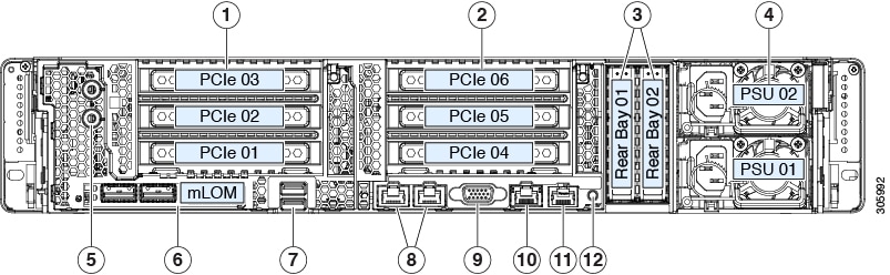
Network and management I/O

Rear panel:

  • One 1-Gb Ethernet dedicated management port (RJ-45 connector)

  • Two 1-Gb/10-Gb BASE-T Ethernet LAN ports (RJ-45 connectors)

    The dual LAN ports can support 1 Gbps and 10 Gbps, depending on the link partner capability.

  • One RS-232 serial port (RJ-45 connector)

  • One VGA video connector port (DB-15 connector)

  • Two USB 3.0 ports

Front panel:

  • One front-panel keyboard/video/mouse (KVM) connector that is used with the KVM cable, which provides two USB 2.0, one VGA, and one DB-9 serial connector.

Modular LOM

One dedicated socket (x16 PCIe lane) that can be used to add an mLOM card for additional rear-panel connectivity.

WoL

The two 1-Gb/10-Gb BASE-T Ethernet LAN ports support the wake-on-LAN (WoL) standard.

Power

Two power supplies, redundant as 1+1:

AC power supplies 1050 W AC each

Do not mix power supply types or wattages in the Cisco CSP 5200.

ACPI

The advanced configuration and power interface (ACPI) 4.0 standard is supported.

Cooling

Six hot-swappable fan modules for front-to-rear cooling.

PCIe I/O

Six horizontal PCIe expansion slots on two PCIe riser assemblies.

See PCIe Slot Specifications for specifications of the slots.

Storage, front-panel

The Cisco CSP 5200 is orderable in the following version:

Small form-factor (SFF) drives, with 24-drive backplane.

  • Front-loading drive bays 1—24 support 2.5-inch SAS/SATA drives.

SAS/SATA drives are hot-swappable.

Other removable media

The SFF drives, 8-drive version of the Cisco CSP 5200 supports a front-loading DVD drive option.

Storage management

The Cisco CSP 5200 has a dedicated internal socket that supports the following storage-controller options:

A PCIe-style Cisco modular RAID controller card (SAS/SATA).

For a detailed list of storage controller options, see Supported Storage Controllers and Cables.

RAID backup

The Cisco CSP 5200 has a mounting bracket on the removable air baffle for one supercap unit that is used with the Cisco modular RAID controller card.

Integrated video

Integrated VGA video.