- Preface
- Overview
- Installing a Cisco Nexus 7004 Switch
- Installing a Cisco Nexus 7009 Chassis
- Installing a Cisco Nexus 7010 Chassis
- Installing a Cisco Nexus 7018 Chassis
- Installing Power Supply Units
- Connecting the Cisco Nexus 7000 Switch to the Network
- Managing system hardware
- Troubleshooting
- Replacement Procedures
- Technical Specifications
- Transceiver and Module Connectors
- Cisco Nexus 7000 Series Accessory Kit Contents
- Chassis and Module LEDs
- Repacking the Nexus 7000 Series Switch for Shipment
- Site Preparation and Maintenance Records
Cisco Nexus 7000 Series Hardware Installation and Reference Guide
Bias-Free Language
The documentation set for this product strives to use bias-free language. For the purposes of this documentation set, bias-free is defined as language that does not imply discrimination based on age, disability, gender, racial identity, ethnic identity, sexual orientation, socioeconomic status, and intersectionality. Exceptions may be present in the documentation due to language that is hardcoded in the user interfaces of the product software, language used based on RFP documentation, or language that is used by a referenced third-party product. Learn more about how Cisco is using Inclusive Language.
- Updated:
- July 8, 2014
Chapter: Repacking the Nexus 7000 Series Switch for Shipment
Repacking the Cisco Nexus 7000 Series Switch for Shipment
This appendix describes how to repack a Cisco Nexus 7000 Series system for shipment. This appendix includes the following sections:
Disconnecting the Cisco Nexus 7000 Series System
Before you can remove the Cisco Nexus 7000 Series system components and repack the system, you must disconnect the system from the AC power source, console, and network as explained in the following topics:
- Powering Down the Cisco Nexus 7000 Series System
- Disconnecting the System from the Console
- Disconnecting the System from the Network

Powering Down the Cisco Nexus 7000 Series System
To power down the Cisco Nexus 7000 Series system, turn the power switch on each power supply from Power to standby, and then disconnect the power cords to each power supply. The system is powered down when the LEDs on each power supply are all off.
Disconnecting the System from the Console
To disconnect the system from the console, you must disconnect each interface cable that connects to the management Ethernet (Mgmt Ethernet) and CMP (available only on Supervisor 1 modules) interfaces on each supervisor module. You must also disconnect the cables and their adapters from the console.
Disconnecting the System from the Network
To disconnect the system from the network, you must remove each I/O cable from the system I/O modules.
Repacking the System Components
You repack the Cisco Nexus 7000 Series system in its shipping materials, which you can order if they are not available at your facility. To make the Cisco Nexus 7000 Series lighter and easier to move, remove its power supply units, its external frames and doors, and, for the Cisco Nexus 7010 switch, its optional air filter before you move the chassis. You should pack each of these components separately. To pack the chassis, you typically use a mechanical lift (required whenever lifting over 120 pounds [54.4 kg]) to move the chassis from the rack to its shipping pallet, where you can package the chassis and its components.
This section includes the following topics:
- Prerequisites for Repacking the System
- Required Tools and Equipment for Repacking the System
- Repacking the Cisco Nexus 7004 Switch
- Repacking the Cisco Nexus 7009 Switch
- Repacking the Cisco Nexus 7010 Switch
- Repacking the Cisco Nexus 7018 Switch
Prerequisites for Repacking the System
You must power down and disconnect the system from the network before you begin removing the switch from the rack or cabinet (see the “Disconnecting the Cisco Nexus 7000 Series System” section).
Required Tools and Equipment for Repacking the System
Before you repack the Cisco Nexus 7000 Series chassis into its original shipping materials, make sure that you have the following tools and equipment:
–![]() Cisco Nexus 7004 chassis—50 lbs (68 kg)
Cisco Nexus 7004 chassis—50 lbs (68 kg)
–![]() Cisco Nexus 7009 chassis—300 lbs (136 kg)
Cisco Nexus 7009 chassis—300 lbs (136 kg)
–![]() Cisco Nexus 7010 chassis—550 lbs (250 kg)
Cisco Nexus 7010 chassis—550 lbs (250 kg)
–![]() Cisco Nexus 7018 chassis—700 lbs (318 kg)
Cisco Nexus 7018 chassis—700 lbs (318 kg)
- Number 1 Phillips screwdriver with torque capability
- Nut driver attachment for screwdriver or ratchet wrench with torque capability (used only for DC power supplies)
- 3/16-inch flat-blade screwdriver
- ESD wrist strap
- Original shipping container and packing materials, which you can order with one of the following part numbers:
–![]() Cisco Nexus 7004 chassis—N7K-C7004-SHPPKG=
Cisco Nexus 7004 chassis—N7K-C7004-SHPPKG=
–![]() Cisco Nexus 7009 chassis—N7K-C7009-SHPPKG=
Cisco Nexus 7009 chassis—N7K-C7009-SHPPKG=
–![]() Cisco Nexus 7010 chassis—N7K-C7010-SHPPKG=
Cisco Nexus 7010 chassis—N7K-C7010-SHPPKG=
–![]() Cisco Nexus 7018 chassis—N7K-C7018-SHPPKG=
Cisco Nexus 7018 chassis—N7K-C7018-SHPPKG=
Repacking the Cisco Nexus 7004 Switch
If you plan to lift the Cisco Nexus 7004 chassis off the rack, you must lighten it to less than 120 pounds (54.4 kg) by removing the power supplies from the chassis. Otherwise, you must position a mechanical lift to hold the chassis as you remove it from the rack.
Before you remove a chassis from the rack, lay its pallet on the floor and set its packing materials nearby. If you do not have the original packing materials for the Cisco Nexus 7004 switch, order another set of these materials (part number N7K-C7004-SHPPKG=).
To repack the Cisco Nexus 7004 switch, follow these steps:
Step 1![]() For each power supply installed in the chassis, turn the power switch to standby (labelled as 0) and verify that its OUTPUT LED is not lit.
For each power supply installed in the chassis, turn the power switch to standby (labelled as 0) and verify that its OUTPUT LED is not lit.
Step 2![]() For each AC power supply, remove the power cord as follows:
For each AC power supply, remove the power cord as follows:
a.![]() Remove the power cable from the power source and verify that none of the power supply LEDs are lit.
Remove the power cable from the power source and verify that none of the power supply LEDs are lit.
b.![]() Lift the power cable retention clip that holds the power plug onto the power supply and pull the plug out of the recepticle on the power supply.
Lift the power cable retention clip that holds the power plug onto the power supply and pull the plug out of the recepticle on the power supply.
Step 3![]() For each DC power supply, remove the power cord as follows:
For each DC power supply, remove the power cord as follows:
a.![]() Verify that the power is turned off at the source (circuit breaker) and that no LEDs are lit on the power supply.
Verify that the power is turned off at the source (circuit breaker) and that no LEDs are lit on the power supply.
b.![]() Remove the power cables from the source.
Remove the power cables from the source.
c.![]() Remove the cover for the terminal box on the DC power supply by removing its three screws and pulling the lid off the box. For the location of the terminal box and the screws that secure its lid, see Figure 6-7.
Remove the cover for the terminal box on the DC power supply by removing its three screws and pulling the lid off the box. For the location of the terminal box and the screws that secure its lid, see Figure 6-7.
d.![]() Remove the two nuts holding each of four lugs to the terminal box.
Remove the two nuts holding each of four lugs to the terminal box.
e.![]() Replace the terminal box cover and secure with three screws.
Replace the terminal box cover and secure with three screws.
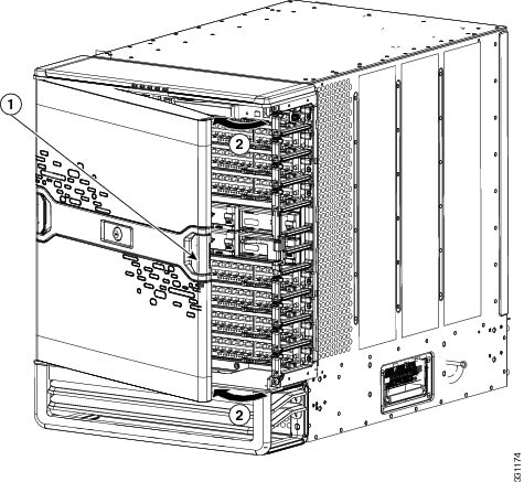
Step 4![]() If there is a front door on the chassis, remove and repack it as follows:
If there is a front door on the chassis, remove and repack it as follows:
a.![]() Set the packing materials for the front door by the chassis.
Set the packing materials for the front door by the chassis.
b.![]() Holding the door on both sides, pull it away from the front of the chassis.
Holding the door on both sides, pull it away from the front of the chassis.
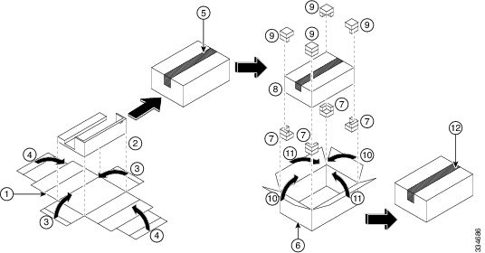
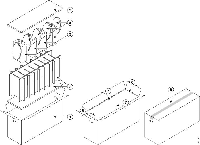
c.![]() Center the door (front side down as shown in Callout 2 in Figure E-1) on center section of the flattened inner box.
Center the door (front side down as shown in Callout 2 in Figure E-1) on center section of the flattened inner box.
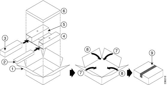
Figure E-1 Packing the Front Door for the Cisco Nexus 7004 Chassis
|
|
|
||
|
|
|
||
|
|
|
||
|
|
|
||
|
|
|
||
|
|
|
d.![]() Fold the two smaller inner box flaps over the door (see Callout 3 in Figure E-1).
Fold the two smaller inner box flaps over the door (see Callout 3 in Figure E-1).
e.![]() Fold the two larger inner box flaps over the door (see Callout 4 in Figure E-1).
Fold the two larger inner box flaps over the door (see Callout 4 in Figure E-1).
f.![]() Tape the larger inner box flaps together and to the box (see Callout 5 in Figure E-1).
Tape the larger inner box flaps together and to the box (see Callout 5 in Figure E-1).
g.![]() Open the outer box (see Callout 6 in Figure E-1).
Open the outer box (see Callout 6 in Figure E-1).
h.![]() Place four corner pads in the inner lower corners of the outer box (see Callout 7 in Figure E-1).
Place four corner pads in the inner lower corners of the outer box (see Callout 7 in Figure E-1).
i.![]() Place the inner box inside the outer box and on the corner pads (see Callout 8 in Figure E-1).
Place the inner box inside the outer box and on the corner pads (see Callout 8 in Figure E-1).
j.![]() Place four corner pads on the upper corners of the inner box (see Callout 9 in Figure E-1).
Place four corner pads on the upper corners of the inner box (see Callout 9 in Figure E-1).
k.![]() Fold the smaller flaps over the inner box (see Callout 10 in Figure E-1).
Fold the smaller flaps over the inner box (see Callout 10 in Figure E-1).
l.![]() Fold the two larger flaps over the inner box (see Callout 11 in Figure E-1).
Fold the two larger flaps over the inner box (see Callout 11 in Figure E-1).
m.![]() Tape the larger flaps together and to the box (see Callout 12 in Figure E-1).
Tape the larger flaps together and to the box (see Callout 12 in Figure E-1).
Step 5![]() If there is an air filter attached to the chassis, remove and repack it as follows:
If there is an air filter attached to the chassis, remove and repack it as follows:
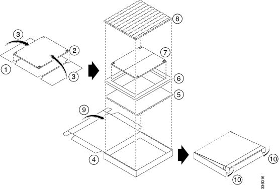
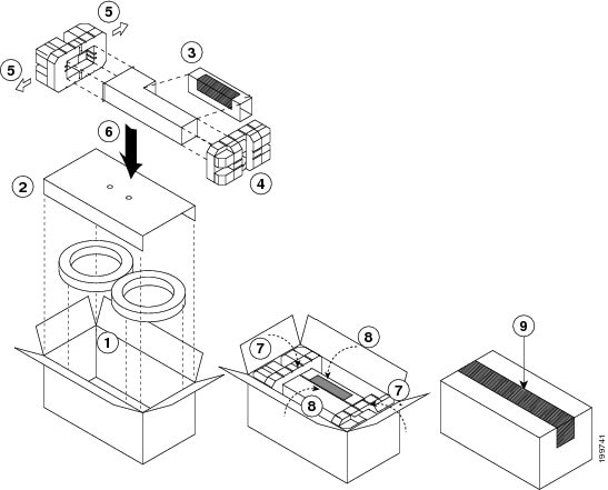
a.![]() Open the air filter box, place a layer of padding in the bottom of the box, and place the four-sided padding in the box (see Callouts 4, 5, and 6 in Figure E-2).
Open the air filter box, place a layer of padding in the bottom of the box, and place the four-sided padding in the box (see Callouts 4, 5, and 6 in Figure E-2).
Figure E-2 Packing the Air Filter for the Cisco Nexus 7004 Chassis
|
|
|
||
|
|
|
Air filter in trifold placedinside the four-sided padding in the air filter box |
|
|
|
|
||
|
|
|
||
|
|
|
Two flaps on air filter box inserted into slots in the box walls. |
b.![]() Unscrew the eight M3 screws that fasten the air filter to the right side of the chassis.
Unscrew the eight M3 screws that fasten the air filter to the right side of the chassis.
c.![]() Remove the air filter from the chassis and center it on the trifold piece of cardboard found with the packing materials (see Callouts 1 and 2 in Figure E-2).
Remove the air filter from the chassis and center it on the trifold piece of cardboard found with the packing materials (see Callouts 1 and 2 in Figure E-2).
d.![]() Fold the two trifold flaps over the air filter (see Callout 3 in Figure E-2).
Fold the two trifold flaps over the air filter (see Callout 3 in Figure E-2).
e.![]() Place the protected air filter inside the four-sided padding in the air filter box (see Callout 7 in Figure E-2).
Place the protected air filter inside the four-sided padding in the air filter box (see Callout 7 in Figure E-2).
f.![]() Place a layer of padding over the air filter in the air filter box (see Callout 8 in Figure E-2).
Place a layer of padding over the air filter in the air filter box (see Callout 8 in Figure E-2).
g.![]() Close the air filter box (see Callout 9 in Figure E-2) and push two flaps on the box cover into slots in the box (see callout 10 in Figure E-2).
Close the air filter box (see Callout 9 in Figure E-2) and push two flaps on the box cover into slots in the box (see callout 10 in Figure E-2).
Step 6![]() Remove the console and management Ethernet cables and any storage media from the supervisor modules.
Remove the console and management Ethernet cables and any storage media from the supervisor modules.
Step 7![]() Remove all of the cables from the I/O modules.
Remove all of the cables from the I/O modules.
Step 8![]() Remove the ground lug and cable from the chassis as follows
Remove the ground lug and cable from the chassis as follows
a.![]() Unscrew the two M4 screws that fasten the ground lug to the chassis (for the location of the chassis grounding pad, see Figure 2-4).
Unscrew the two M4 screws that fasten the ground lug to the chassis (for the location of the chassis grounding pad, see Figure 2-4).
b.![]() Place the screws in a bag for small parts.
Place the screws in a bag for small parts.
Step 9![]() Remove the cable management frames as follows:
Remove the cable management frames as follows:
a.![]() On one of the two cable management frames, remove the three M3 screws that fasten the frame to the chassis and pull the frame off of the chassis. For the locations of these screws, see Figure 2-5.
On one of the two cable management frames, remove the three M3 screws that fasten the frame to the chassis and pull the frame off of the chassis. For the locations of these screws, see Figure 2-5.
b.![]() Place the screws in the bag for small accessory kit parts.
Place the screws in the bag for small accessory kit parts.
c.![]() Repeat Steps 9a and 9b for the other cable management frame.
Repeat Steps 9a and 9b for the other cable management frame.
Step 10![]() Prepare to remove the chassis from the rack by doing one of the following:
Prepare to remove the chassis from the rack by doing one of the following:
a.![]() If you are going to lift the chassis off the rack, ensure that it weighs less than 120 pounds (54.4 kg) by removing the power supplies. To remove a power supply, move and hold its ejector lever to the left and pull the power supply part way out of the chassis. Place your other hand on it, pull it fully out of the chassis.
If you are going to lift the chassis off the rack, ensure that it weighs less than 120 pounds (54.4 kg) by removing the power supplies. To remove a power supply, move and hold its ejector lever to the left and pull the power supply part way out of the chassis. Place your other hand on it, pull it fully out of the chassis.
b.![]() If you are using a mechanical lift to move the chassis (this is required if it weighs more than 120 pounds [54.4 kg]), position the lift under the chassis or, if the chassis is sitting on another chassis in the rack, position the lift immediately in front of the rack at the level of the chassis bottom or no more than 0.25 inches (0.6 cm) lower than the chassis.
If you are using a mechanical lift to move the chassis (this is required if it weighs more than 120 pounds [54.4 kg]), position the lift under the chassis or, if the chassis is sitting on another chassis in the rack, position the lift immediately in front of the rack at the level of the chassis bottom or no more than 0.25 inches (0.6 cm) lower than the chassis.
Step 11![]() With the chassis supported below by a mechanical lift or by another chassis or by two people holding it, unscrew the ten M4 x 6 mm screws that fasten the chassis to the rack. Place the screws in the small parts bag for the accessory kit.
With the chassis supported below by a mechanical lift or by another chassis or by two people holding it, unscrew the ten M4 x 6 mm screws that fasten the chassis to the rack. Place the screws in the small parts bag for the accessory kit.
Step 12![]() Place the bottom of the packing box on the pallet with the open side facing up (see callouts 1 and 2 in Figure E-3).
Place the bottom of the packing box on the pallet with the open side facing up (see callouts 1 and 2 in Figure E-3).
Figure E-3 Packing the Cisco Nexus 7004 Chassis
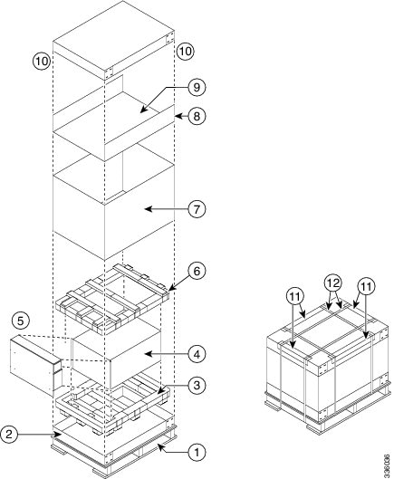
Step 13![]() Place one of the foam pads (Callout 3 in Figure E-3) inside the box bottom.
Place one of the foam pads (Callout 3 in Figure E-3) inside the box bottom.
Step 14![]() Move the chassis from the rack and to its pallet in one of the following ways:
Move the chassis from the rack and to its pallet in one of the following ways:
- If the chassis is sitting on a mechanical lift, use the mechanical lift to move the chassis from the rack to the pallet.
- If the chassis is sitting on top of another chassis, use two people to push the chassis all the way onto the mechanical lift placed in front of the chassis, and then use the mechanical lift to move the chassis to the pallet.
- If you are using two or more people to lift the chassis, lift the chassis out of the rack and move it to the pallet.
Step 15![]() If the chassis is on a mechanical lift, place the lift next to the pallet, position the bottom of the chassis no more than 0.25 inches [0.64 cm] above the top of the padding on the pallet, and use two persons to push or lift the chassis onto the padding. Make sure that the rear of the chassis is placed against one of the padding walls (that leaves an open area in the padding in front of the chassis).
If the chassis is on a mechanical lift, place the lift next to the pallet, position the bottom of the chassis no more than 0.25 inches [0.64 cm] above the top of the padding on the pallet, and use two persons to push or lift the chassis onto the padding. Make sure that the rear of the chassis is placed against one of the padding walls (that leaves an open area in the padding in front of the chassis).
Step 16![]() If you removed the power supplies before moving the chassis, replace each power supply in the chassis as follows:
If you removed the power supplies before moving the chassis, replace each power supply in the chassis as follows:
a.![]() Have two people tilt the front of the chassis up about 2 inches (5 cm).
Have two people tilt the front of the chassis up about 2 inches (5 cm).
b.![]() Holding the bottom of the power supply with one hand and its front handle with the other hand, align the power supply to an open power supply bay and push the power supply fully into the slot until its latch clicks.
Holding the bottom of the power supply with one hand and its front handle with the other hand, align the power supply to an open power supply bay and push the power supply fully into the slot until its latch clicks.
c.![]() Repeat steps 17b for each power supply that you need to put back in the chassis.
Repeat steps 17b for each power supply that you need to put back in the chassis.
d.![]() Place the chassis back down on the padding.
Place the chassis back down on the padding.
Step 17![]() Place the cardboard insert in the remaining open area in the padding and in front of the chassis (see Callout 5 in Figure E-3).
Place the cardboard insert in the remaining open area in the padding and in front of the chassis (see Callout 5 in Figure E-3).
Step 18![]() Place the foam padding on top of the chassis (see Callout 6 in Figure E-3).
Place the foam padding on top of the chassis (see Callout 6 in Figure E-3).
Step 19![]() Place the four-sided box around the chassis and the top pallet. (see Callout 7 in Figure E-3).
Place the four-sided box around the chassis and the top pallet. (see Callout 7 in Figure E-3).
Step 20![]() Place the accessory tray inside the four-sided box and on top of the padding (see Callout 8 in Figure E-3).
Place the accessory tray inside the four-sided box and on top of the padding (see Callout 8 in Figure E-3).
Step 21![]() Place the accessory kit and the front door kit in the accessory tray (see Callout 9 in Figure E-3).
Place the accessory kit and the front door kit in the accessory tray (see Callout 9 in Figure E-3).
Step 22![]() Place the cardboard top on the chassis box (see callout 10 in Figure E-3).
Place the cardboard top on the chassis box (see callout 10 in Figure E-3).
Step 23![]() Place four edge protectors (Callout 11 in Figure E-3) along the top edges of the cardboard top where you will be placing the packing straps.
Place four edge protectors (Callout 11 in Figure E-3) along the top edges of the cardboard top where you will be placing the packing straps.
Step 24![]() Fasten the top of the box to the box and pallet with two packing straps (see Callout 12 in Figure E-3).
Fasten the top of the box to the box and pallet with two packing straps (see Callout 12 in Figure E-3).
Repacking the Cisco Nexus 7009 Switch
Before you remove a Cisco Nexus 7009 switch chassis from a rack, lay its two pallets (two pallets bolted together) on the floor and set its packing materials nearby. If you do not have the original packing materials, order another set of these materials (part number N7K-C7009-SHPPKG=).
To repack the Cisco Nexus 7009 switch, follow these steps:
Step 1![]() Turn the power switch on each power supply to standby (labelled as STBY) and verify that the OUTPUT LED is not lit.
Turn the power switch on each power supply to standby (labelled as STBY) and verify that the OUTPUT LED is not lit.
Step 2![]() For each AC power supply, remove the power cords as follows:
For each AC power supply, remove the power cords as follows:
a.![]() Remove one or two power cables from the power source and verify that all of the power supply LEDs are off.
Remove one or two power cables from the power source and verify that all of the power supply LEDs are off.
b.![]() If you are removing a 6-kW power supply, unscrew the screw on the cable retention device that holds the power plug onto the power supply and pull each power-cable plug off the power supply.
If you are removing a 6-kW power supply, unscrew the screw on the cable retention device that holds the power plug onto the power supply and pull each power-cable plug off the power supply.

Note![]() For a 7.5-kW power supply, you cannot remove the power cords from it because the cables are permanently attached.
For a 7.5-kW power supply, you cannot remove the power cords from it because the cables are permanently attached.
Step 3![]() For each DC power supply, shut off the input power and remove the power cords as follows:
For each DC power supply, shut off the input power and remove the power cords as follows:
a.![]() Turn the power switch on each power supply to standby (labelled as STBY) and verify that the OUTPUT LEDs are off.
Turn the power switch on each power supply to standby (labelled as STBY) and verify that the OUTPUT LEDs are off.
b.![]() Turn off the DC input power by manually turning off each input circuit at its circuit breaker.
Turn off the DC input power by manually turning off each input circuit at its circuit breaker.

Warning![]() Before performing any of the following procedures, ensure that power is removed from the DC circuit. Statement 1003
Before performing any of the following procedures, ensure that power is removed from the DC circuit. Statement 1003
c.![]() Verify that the input power is completely off by making sure that all of the LEDs on the DC power supplies are off.
Verify that the input power is completely off by making sure that all of the LEDs on the DC power supplies are off.
d.![]() Detach each of the power cables from the powered down DC power source or DC power interface unit (PIU).
Detach each of the power cables from the powered down DC power source or DC power interface unit (PIU).
Warning![]() Hazardous voltage or energy may be present on DC power terminals. Always replace cover when terminals are not in service. Be sure uninsulated conductors are not accessible when cover is in place. Statement 1075
Hazardous voltage or energy may be present on DC power terminals. Always replace cover when terminals are not in service. Be sure uninsulated conductors are not accessible when cover is in place. Statement 1075
e.![]() For each of the power plugs attached to the DC power supply, completely unscrew the two screws that hold it to the power supply and unplug it.
For each of the power plugs attached to the DC power supply, completely unscrew the two screws that hold it to the power supply and unplug it.
f.![]() Disconnect the grounding lug from the lower front side of the power supply by unscrewing its two M6 nuts and pulling the grounding lug off of the power supply. For the location of the grounding pad, see Figure 6-2.
Disconnect the grounding lug from the lower front side of the power supply by unscrewing its two M6 nuts and pulling the grounding lug off of the power supply. For the location of the grounding pad, see Figure 6-2.
g.![]() Place the power cords in the accessory kit box for this switch.
Place the power cords in the accessory kit box for this switch.
Step 4![]() Remove each power supply unit and repack it as follows:
Remove each power supply unit and repack it as follows:
Note![]() These instructions are for the multi-unit power supply box that comes with newer Cisco Nexus 7010 switches. If you have the single-unit box for the 6-kW AC power supply unit, see Figure E-15 for packing instructions. If you have the single-unit box for the 6-kW DC power supply unit, see Figure 10-3 for packing instructions.
These instructions are for the multi-unit power supply box that comes with newer Cisco Nexus 7010 switches. If you have the single-unit box for the 6-kW AC power supply unit, see Figure E-15 for packing instructions. If you have the single-unit box for the 6-kW DC power supply unit, see Figure 10-3 for packing instructions.
a.![]() Open the box for the power supply units and make sure that the cardboard holders are set up inside the box (see Callout 1 in Figure E-4).
Open the box for the power supply units and make sure that the cardboard holders are set up inside the box (see Callout 1 in Figure E-4).
Figure E-4 Packing Power Supply Units in a Multi-Unit Box
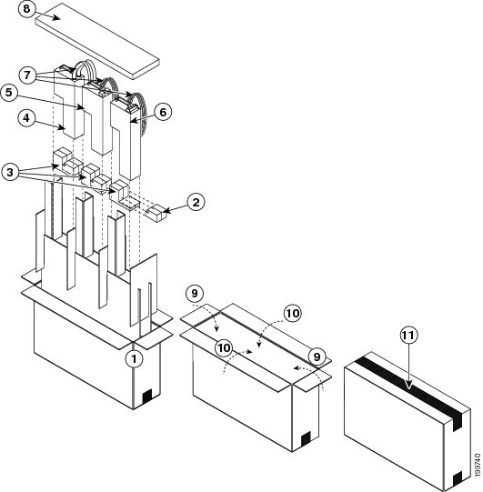
b.![]() If you are packing a DC power supply unit, remove the detachable portion from the bottom pad (see Callout 2 in Figure E-4). This detachable portion of the pad is included only when packing the shorter AC power supply units.
If you are packing a DC power supply unit, remove the detachable portion from the bottom pad (see Callout 2 in Figure E-4). This detachable portion of the pad is included only when packing the shorter AC power supply units.
c.![]() Insert the bottom pad, uneven side facing up, into the slot that you are filling (see Callout 3 in Figure E-4).
Insert the bottom pad, uneven side facing up, into the slot that you are filling (see Callout 3 in Figure E-4).
d.![]() Unscrew the four captive screws on the power supply so that they no longer connect with the chassis.
Unscrew the four captive screws on the power supply so that they no longer connect with the chassis.
e.![]() With one hand on the handle of the power supply, pull the unit partially out of the chassis.
With one hand on the handle of the power supply, pull the unit partially out of the chassis.
f.![]() Place your other hand underneath the power supply to support it, and then pull it fully out of the chassis.
Place your other hand underneath the power supply to support it, and then pull it fully out of the chassis.
g.![]() Place the power supply in its ESD packing bag and insert the bagged power supply in one of the three larger slots in the packing box (see Callouts 4, 5, and 6 in Figure E-4).
Place the power supply in its ESD packing bag and insert the bagged power supply in one of the three larger slots in the packing box (see Callouts 4, 5, and 6 in Figure E-4).
Note![]() For easier handling of a multi-unit box, be sure to arrange the power supplies so their weight is balanced in the box. If you are packing only one unit, place it in the large slot in the middle of the box. If you are packing two units, place them in the large slots at each end of the box.
For easier handling of a multi-unit box, be sure to arrange the power supplies so their weight is balanced in the box. If you are packing only one unit, place it in the large slot in the middle of the box. If you are packing two units, place them in the large slots at each end of the box.
h.![]() Coil the power cables and insert them in the slots next to the power supply (see Callout 7 in Figure E-4).
Coil the power cables and insert them in the slots next to the power supply (see Callout 7 in Figure E-4).
i.![]() If there is another power supply to pack, repeat Steps 4a through 4h.
If there is another power supply to pack, repeat Steps 4a through 4h.
j.![]() Place the top padding above the power supplies (see Callout 8 in Figure E-4).
Place the top padding above the power supplies (see Callout 8 in Figure E-4).
k.![]() Fold the two narrow flaps of the box over the padding (see Callout 9 in Figure E-4).
Fold the two narrow flaps of the box over the padding (see Callout 9 in Figure E-4).
l.![]() Fold the two wide flaps over the narrow flaps (see Callout 10 in Figure E-4).
Fold the two wide flaps over the narrow flaps (see Callout 10 in Figure E-4).
m.![]() Tape the wide flaps together and to the box (see Callout 11 in Figure E-4) with packing tape.
Tape the wide flaps together and to the box (see Callout 11 in Figure E-4) with packing tape.
Warning![]() When installing or replacing the unit, the ground connection must always be made first and disconnected last. Statement 1046
When installing or replacing the unit, the ground connection must always be made first and disconnected last. Statement 1046
Step 5![]() Disconnect the switch from the console and the network as follows:
Disconnect the switch from the console and the network as follows:
a.![]() For each supervisor module, disconnect the cables connected to the console, Com/AUX, Management, and CMP Management ports.
For each supervisor module, disconnect the cables connected to the console, Com/AUX, Management, and CMP Management ports.
Note![]() The CMP feature is available only on Supervisor 1 modules.
The CMP feature is available only on Supervisor 1 modules.
b.![]() Disconnect all of the cables from each of the I/O modules.
Disconnect all of the cables from each of the I/O modules.
Step 6![]() Disconnect the grounding lug from the front of the chassis as follows:
Disconnect the grounding lug from the front of the chassis as follows:
a.![]() Unscrew the two M4 screws that hold each ground lug to the chassis. For the location of the grounding pad on the chassis, see Figure 3-12.
Unscrew the two M4 screws that hold each ground lug to the chassis. For the location of the grounding pad on the chassis, see Figure 3-12.
b.![]() Remove the grounding lug from the chassis and place the two screws in the accessory kit.
Remove the grounding lug from the chassis and place the two screws in the accessory kit.
Step 7![]() If the chassis includes the optional front door and air-intake frame, remove and repack them as follows:
If the chassis includes the optional front door and air-intake frame, remove and repack them as follows:
a.![]() Open the door by pulling one of its latch handles out until it clicks (the handle clicks when you pull it out about 30 degrees) and rotate the door away from the chassis (see Figure E-5).
Open the door by pulling one of its latch handles out until it clicks (the handle clicks when you pull it out about 30 degrees) and rotate the door away from the chassis (see Figure E-5).
Figure E-5 Removing One Side of the Front Door
|
|
|
b.![]() Press the locking button on the back side of the door (behind the opened latch handle) so that the latch handle flattens to the front side of the door.
Press the locking button on the back side of the door (behind the opened latch handle) so that the latch handle flattens to the front side of the door.
c.![]() Hold the opened side of the door with one hand and use your other hand to open the latch handle on the hinged side of the door until the handle clicks. Use both hands to remove the door from the chassis.
Hold the opened side of the door with one hand and use your other hand to open the latch handle on the hinged side of the door until the handle clicks. Use both hands to remove the door from the chassis.
d.![]() Press the locking button on the inside surface of the door behind the opened latch to flatten the latch handle to the front side of the door.
Press the locking button on the inside surface of the door behind the opened latch to flatten the latch handle to the front side of the door.
e.![]() Wrap the door in the bubble wrap included in the front-door and air-intake-frame kit. Set this by the kit for packing later in this process.
Wrap the door in the bubble wrap included in the front-door and air-intake-frame kit. Set this by the kit for packing later in this process.
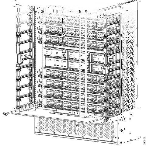
f.![]() Remove the bottom hinge bracket by removing four screws that attach it to the chassis and four screws that attach it to the right and left cable management frames (two screws for each frame) as shown in Figure E-6. Place the bracket with the front door wrapped in bubble wrap and put the screws in a bag for small door parts.
Remove the bottom hinge bracket by removing four screws that attach it to the chassis and four screws that attach it to the right and left cable management frames (two screws for each frame) as shown in Figure E-6. Place the bracket with the front door wrapped in bubble wrap and put the screws in a bag for small door parts.
Figure E-6 Removing the Bottom Hinge Bracket from the Chassis
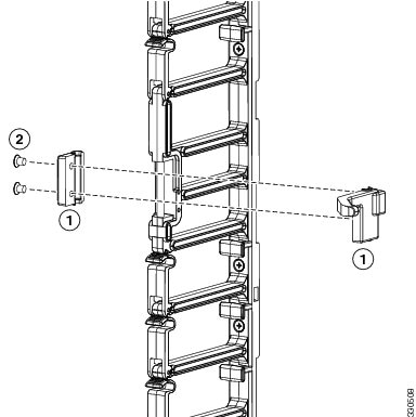
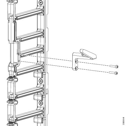
g.![]() Remove the door stop from the right cable management frame by loosening and removing its two M4 screws (see Figure E-7). Pull the two pieces of the door stop off the cable management frame and put the two pieces and two screws in the small parts bag.
Remove the door stop from the right cable management frame by loosening and removing its two M4 screws (see Figure E-7). Pull the two pieces of the door stop off the cable management frame and put the two pieces and two screws in the small parts bag.
Figure E-7 Removing the Door Stop from the Right Cable Management Frame
|
|
|
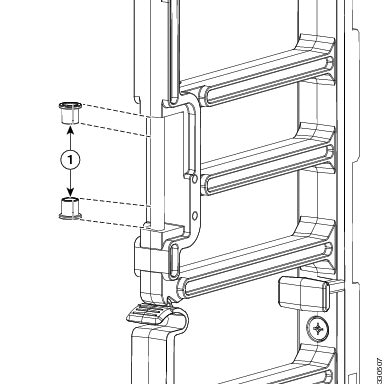
h.![]() Pull off the two bushings from the post that the right door stop was attached to (see Figure E-8). Put the bushings in the small parts bag.
Pull off the two bushings from the post that the right door stop was attached to (see Figure E-8). Put the bushings in the small parts bag.
Figure E-8 Removing the Bushings from the Right Cable Management Frame
|
|
|
i.![]() Remove the door stop on the left cable management frame by loosening and removing its two M3 screws (see Figure E-9). Place the door stop and screws in the small parts bag.
Remove the door stop on the left cable management frame by loosening and removing its two M3 screws (see Figure E-9). Place the door stop and screws in the small parts bag.
Figure E-9 Removing the Door Stop from the Left Cable Management Frame
|
|
|
Two M3 screws that hold the door stop to the cable management frame. |
j.![]() Remove the air-intake frame by unscrewing its two captive screws (one screw on each side) and pulling the frame off the chassis.
Remove the air-intake frame by unscrewing its two captive screws (one screw on each side) and pulling the frame off the chassis.
k.![]() Open the box for the front door and air-intake frame kit (see Callout 1 in Figure E-10).
Open the box for the front door and air-intake frame kit (see Callout 1 in Figure E-10).
Figure E-10 Repacking the Front Door and Air Intake Frame
|
|
|
||
|
|
|
||
|
|
|
||
|
|
Protective cardboard insert with slots available for the hinge bracket and air-intake frame |
|
|
|
|
|
l.![]() Slide the air-intake frame and the hinge bracket inside separate slots of the protective cardboard insert (see Callouts 2, 3, and 4 in Figure E-10), and place the cardboard insert in the bottom of the box.
Slide the air-intake frame and the hinge bracket inside separate slots of the protective cardboard insert (see Callouts 2, 3, and 4 in Figure E-10), and place the cardboard insert in the bottom of the box.
m.![]() Place the small parts bag in the open slot of the cardboard insert (see Callout 5 in Figure E-10).
Place the small parts bag in the open slot of the cardboard insert (see Callout 5 in Figure E-10).
n.![]() Place the front door, which is wrapped in bubblewrap, inside the box (see callout 6 in Figure E-10).
Place the front door, which is wrapped in bubblewrap, inside the box (see callout 6 in Figure E-10).
o.![]() Fold the flaps of the box on top of the front door (see Callouts 7 and 8 in Figure E-10).
Fold the flaps of the box on top of the front door (see Callouts 7 and 8 in Figure E-10).
p.![]() Secure the top two flaps together and to the box using packing tape (see Callout 9 in Figure E-10).
Secure the top two flaps together and to the box using packing tape (see Callout 9 in Figure E-10).
Step 8![]() Remove and repack the cable management frames as follows:
Remove and repack the cable management frames as follows:
a.![]() Remove the top cable management frame by unscrewing its four M4 screws (two on each side as shown in Figure E-11) and pulling the frame off the chassis. Place the screws in a bag for small accessory kit parts.
Remove the top cable management frame by unscrewing its four M4 screws (two on each side as shown in Figure E-11) and pulling the frame off the chassis. Place the screws in a bag for small accessory kit parts.
Figure E-11 Removing the Top Cable Management Frame
|
|
Four M4 pan-head screws that attach the top frame to each side frame (two screws for each side frame) |
|
b.![]() Remove one of the side cable managment frames by unscrewing its six M4 screws, and lifting the frame up and away from the chassis. Place the screws in a bag for small accessory kit parts (see Figure E-12).
Remove one of the side cable managment frames by unscrewing its six M4 screws, and lifting the frame up and away from the chassis. Place the screws in a bag for small accessory kit parts (see Figure E-12).
Figure E-12 Removing a Side Cable Management Frame
|
|
|
||
|
|
|
c.![]() Remove the other cable management frame by repeating Step 7b.
Remove the other cable management frame by repeating Step 7b.
Step 9![]() Disconnect the ground cable from the chassis by loosening and removing its two M4 screws. Place the screws in a small parts bag for the accessory kit. For a location of the grounding pad, see Figure 3-12.
Disconnect the ground cable from the chassis by loosening and removing its two M4 screws. Place the screws in a small parts bag for the accessory kit. For a location of the grounding pad, see Figure 3-12.
Step 10![]() Remove the chassis from the rack by following these steps:
Remove the chassis from the rack by following these steps:
a.![]() Unscrew 12 screws holding the chassis to each side of the rack (6 screws on each side). Place the screws in the small parts bag for the accessory kit.
Unscrew 12 screws holding the chassis to each side of the rack (6 screws on each side). Place the screws in the small parts bag for the accessory kit.
Figure E-13 Screws to Remove to Detach the Chassis from the Rack (Center-Mount Bracket Shown)
|
|
|
b.![]() Place a mechanical lift in front of the rack and elevate its platform to the bottom of the chassis (or no more than 0.25 inches [0.6 cm] below the bottom of the chassis).
Place a mechanical lift in front of the rack and elevate its platform to the bottom of the chassis (or no more than 0.25 inches [0.6 cm] below the bottom of the chassis).
c.![]() Use two persons to push the chassis fully onto the mechanical lift.
Use two persons to push the chassis fully onto the mechanical lift.
d.![]() Use the mechanical lift to move the chassis to its pallet. Position the lift next to the pallet and elevate the bottom of the chassis to the level of the top of the pallet (or no more than 0.25 inches [0.6 cm] above the pallet).
Use the mechanical lift to move the chassis to its pallet. Position the lift next to the pallet and elevate the bottom of the chassis to the level of the top of the pallet (or no more than 0.25 inches [0.6 cm] above the pallet).
e.![]() Use two persons to push the chassis fully onto the pallet, and center the chassis on the pallet.
Use two persons to push the chassis fully onto the pallet, and center the chassis on the pallet.
Step 11![]() Attach two angle brackets to the raised portion of the pallet between the chassis and the pallet edge. Do not tighten the screws that hold these brackets to the pallet—you will need to adjust their placement after you place the chassis on the pallet (see Callout 2 in Figure E-3).
Attach two angle brackets to the raised portion of the pallet between the chassis and the pallet edge. Do not tighten the screws that hold these brackets to the pallet—you will need to adjust their placement after you place the chassis on the pallet (see Callout 2 in Figure E-3).
Figure E-14 Packing the Cisco Nexus 7009 Chassis
|
|
|
||
|
|
|
||
|
|
|
||
|
|
|
||
|
|
Four-sided box placed around chassis and top layer of pallet |
|
Step 12![]() Attach two more angle brackets to the pallet on the other side of the chassis.
Attach two more angle brackets to the pallet on the other side of the chassis.
Step 13![]() Attach each of the four brackets to the chassis using two screws and tighten each screw.
Attach each of the four brackets to the chassis using two screws and tighten each screw.
Step 14![]() Tighten the two screws that hold each of the four brackets so that the chassis cannot move on the pallet.
Tighten the two screws that hold each of the four brackets so that the chassis cannot move on the pallet.
Step 15![]() Place the foam padding on top of the chassis (see Callout 4 in Figure E-3).
Place the foam padding on top of the chassis (see Callout 4 in Figure E-3).
Step 16![]() Place the four sided box around the chassis and the top layer of the pallet. (see Callout 5 in Figure E-3).
Place the four sided box around the chassis and the top layer of the pallet. (see Callout 5 in Figure E-3).
Step 17![]() Place the accessories tray inside the chassis box and on top of the chassis padding (see Callout 6 in Figure E-3).
Place the accessories tray inside the chassis box and on top of the chassis padding (see Callout 6 in Figure E-3).
Step 18![]() Place the accessory kit and the front-door kit in the accessories box (see Callout 7 in Figure E-3).
Place the accessory kit and the front-door kit in the accessories box (see Callout 7 in Figure E-3).
Step 19![]() Place the cardboard top on the chassis box (see callout 8 in Figure E-3).
Place the cardboard top on the chassis box (see callout 8 in Figure E-3).
Step 20![]() Place four edge protectors along the top edges of the cardboard top where you will be placing the packing straps (see Callout 9 in Figure E-3).
Place four edge protectors along the top edges of the cardboard top where you will be placing the packing straps (see Callout 9 in Figure E-3).
Step 21![]() Fasten the top of the box to the chassis box and pallet with two packing straps (see Callout 10 in Figure E-3).
Fasten the top of the box to the chassis box and pallet with two packing straps (see Callout 10 in Figure E-3).
Repacking the Cisco Nexus 7010 Switch
If you do not have the original packing materials for the Cisco Nexus 7010 switch, you must order another set of these materials (order part number is N7K-C7010-SHPPKG=).
To repack the Cisco Nexus 7010 switch, follow these steps:
Step 1![]() Turn the power switch on each power supply to standby (STBY). The OUTPUT LED turns off.
Turn the power switch on each power supply to standby (STBY). The OUTPUT LED turns off.
Step 2![]() For each AC power supply, remove the power cords as follows:
For each AC power supply, remove the power cords as follows:
a.![]() Remove the one or two power plugs from the power source. All of the power supply LEDs turn off.
Remove the one or two power plugs from the power source. All of the power supply LEDs turn off.
b.![]() If you are removing a 6-kW AC power supply, unscrew the screw on the cable retention device and pull the one or two plugs off the power supply.
If you are removing a 6-kW AC power supply, unscrew the screw on the cable retention device and pull the one or two plugs off the power supply.
Note![]() For a 7.5-kW power supply, you cannot remove the power cords from them because they are permanently attached.
For a 7.5-kW power supply, you cannot remove the power cords from them because they are permanently attached.
Step 3![]() For each DC power supply, shut off the input power and remove the power cords as follows:
For each DC power supply, shut off the input power and remove the power cords as follows:
a.![]() Turn off the DC input power by manually turning off each input circuit at its circuit breaker.
Turn off the DC input power by manually turning off each input circuit at its circuit breaker.
Warning![]() Before performing any of the following procedures, ensure that power is removed from the DC circuit. Statement 1003
Before performing any of the following procedures, ensure that power is removed from the DC circuit. Statement 1003
b.![]() Verify that the input power is completely off by making sure that all of the LEDs on the DC power supplies are off.
Verify that the input power is completely off by making sure that all of the LEDs on the DC power supplies are off.
c.![]() Detach each of the power cables from the powered down DC power source or DC power interface unit (PIU).
Detach each of the power cables from the powered down DC power source or DC power interface unit (PIU).
Warning![]() Hazardous voltage or energy may be present on DC power terminals. Always replace cover when terminals are not in service. Be sure uninsulated conductors are not accessible when cover is in place. Statement 1075
Hazardous voltage or energy may be present on DC power terminals. Always replace cover when terminals are not in service. Be sure uninsulated conductors are not accessible when cover is in place. Statement 1075
d.![]() For each of the power plugs attached to the DC power supply, completely unscrew the two screws that hold it to the power supply and unplug it.
For each of the power plugs attached to the DC power supply, completely unscrew the two screws that hold it to the power supply and unplug it.
e.![]() Disconnect the grounding lug from the lower front side of the power supply unit by unscrewing its two M6 nuts and pulling the grounding lug off of the power supply unit. For the location of the grounding pad, see Figure 6-2.
Disconnect the grounding lug from the lower front side of the power supply unit by unscrewing its two M6 nuts and pulling the grounding lug off of the power supply unit. For the location of the grounding pad, see Figure 6-2.
f.![]() Place the power cords for 6-kW power supplies in the accessory kit (the power cords for the 7.5 kW power supplies are attached to and packed with the power supply.
Place the power cords for 6-kW power supplies in the accessory kit (the power cords for the 7.5 kW power supplies are attached to and packed with the power supply.
Warning![]() When installing or replacing the unit, the ground connection must always be made first and disconnected last. Statement 1046
When installing or replacing the unit, the ground connection must always be made first and disconnected last. Statement 1046
Step 4![]() Remove each power supply unit and repack it as follows:
Remove each power supply unit and repack it as follows:
Note![]() These instructions are for the multi-unit power supply box that comes with newer Cisco Nexus 7010 switches. If you have the single-unit box for the 6-kW AC power supply unit, see Figure E-15 for packing instructions. If you have the single-unit box for the 6-kW DC power supply unit, see Figure 10-3 for packing instructions.
These instructions are for the multi-unit power supply box that comes with newer Cisco Nexus 7010 switches. If you have the single-unit box for the 6-kW AC power supply unit, see Figure E-15 for packing instructions. If you have the single-unit box for the 6-kW DC power supply unit, see Figure 10-3 for packing instructions.
a.![]() Open the box for the power supply units and make sure that the cardboard holders are set up inside the box (see Callout 1 in Figure E-15).
Open the box for the power supply units and make sure that the cardboard holders are set up inside the box (see Callout 1 in Figure E-15).
Figure E-15 Packing Power Supply Units in a Multi-Unit Box
b.![]() If you are packing a DC power supply unit, remove the detachable portion from the bottom pad (see Callout 2 in Figure E-15). This detachable portion of the pad is included only when packing the shorter AC power supply units.
If you are packing a DC power supply unit, remove the detachable portion from the bottom pad (see Callout 2 in Figure E-15). This detachable portion of the pad is included only when packing the shorter AC power supply units.
c.![]() Insert the bottom pad, uneven side facing up, into the slot that you are filling (see Callout 3 in Figure E-15).
Insert the bottom pad, uneven side facing up, into the slot that you are filling (see Callout 3 in Figure E-15).
d.![]() Unscrew the four captive screws on the power supply unit so that they no longer connect with the chassis.
Unscrew the four captive screws on the power supply unit so that they no longer connect with the chassis.
e.![]() With one hand on the handle of the power supply unit, pull the unit partially out of the chassis.
With one hand on the handle of the power supply unit, pull the unit partially out of the chassis.
f.![]() Place your other hand underneath the power supply unit to support the unit, and then pull the unit fully out of the chassis.
Place your other hand underneath the power supply unit to support the unit, and then pull the unit fully out of the chassis.
g.![]() Place the power supply unit in its ESD packing bag and insert the bagged power supply unit in one of the three larger slots in the packing box (see Callouts 4, 5, and 6 in Figure E-15).
Place the power supply unit in its ESD packing bag and insert the bagged power supply unit in one of the three larger slots in the packing box (see Callouts 4, 5, and 6 in Figure E-15).
Note![]() For easier handling of a multi-unit box, be sure to arrange the power supply units so their weight is balanced in the box. If you are packing only one unit, place it in the large slot in the middle of the box. If you are packing two units, place them in the large slots at each end of the box.
For easier handling of a multi-unit box, be sure to arrange the power supply units so their weight is balanced in the box. If you are packing only one unit, place it in the large slot in the middle of the box. If you are packing two units, place them in the large slots at each end of the box.
h.![]() Coil the power cables and insert them in the slots next to the power supply unit (see Callout 7 in Figure E-15).
Coil the power cables and insert them in the slots next to the power supply unit (see Callout 7 in Figure E-15).
i.![]() If there is another power supply unit to pack, repeat Steps 4a through 4h.
If there is another power supply unit to pack, repeat Steps 4a through 4h.
j.![]() Place the top padding above the power supply units (see Callout 8 in Figure E-15).
Place the top padding above the power supply units (see Callout 8 in Figure E-15).
k.![]() Fold the two narrow flaps of the box over the padding (see Callout 9 in Figure E-15).
Fold the two narrow flaps of the box over the padding (see Callout 9 in Figure E-15).
l.![]() Fold the two wide flaps over the narrow flaps (see Callout 10 in Figure E-15).
Fold the two wide flaps over the narrow flaps (see Callout 10 in Figure E-15).
m.![]() Tape the wide flaps together and to the box (see Callout 11 in Figure E-15) with packing tape.
Tape the wide flaps together and to the box (see Callout 11 in Figure E-15) with packing tape.
Step 5![]() Disconnect the switch from the console and the network as follows:
Disconnect the switch from the console and the network as follows:
a.![]() On each supervisor module, disconnect the cables connected to the Console, Com/AUX, Management, and CMP Management ports.
On each supervisor module, disconnect the cables connected to the Console, Com/AUX, Management, and CMP Management ports.
Note![]() The CMP feature is available on only Supervisor 1 modules.
The CMP feature is available on only Supervisor 1 modules.
b.![]() Disconnect all of the cables from each of the I/O modules.
Disconnect all of the cables from each of the I/O modules.
Step 6![]() Disconnect the one or two chassis grounding connections as follows:
Disconnect the one or two chassis grounding connections as follows:
a.![]() Unscrew the two M4 screws that hold each ground lug to the chassis. For the locations of the two grounding pads on the Cisco Nexus 7010 switch, see Figure 4-6 and Figure 4-7.
Unscrew the two M4 screws that hold each ground lug to the chassis. For the locations of the two grounding pads on the Cisco Nexus 7010 switch, see Figure 4-6 and Figure 4-7.
b.![]() Remove the grounding lug from the chassis and place the screws in the accessory kit.
Remove the grounding lug from the chassis and place the screws in the accessory kit.
Step 7![]() If the chassis includes an optional air filter, remove it as follows:
If the chassis includes an optional air filter, remove it as follows:
a.![]() On the lower left side and right side of the air filter, loosen the captive screw (one on each side) until it no longer connects with the chassis.
On the lower left side and right side of the air filter, loosen the captive screw (one on each side) until it no longer connects with the chassis.
b.![]() On the upper left side and right side of the air filter, simultaneously pull out the two spring pins (one on each side) and then pull the air filter away from the EMI frame and chassis.
On the upper left side and right side of the air filter, simultaneously pull out the two spring pins (one on each side) and then pull the air filter away from the EMI frame and chassis.
Step 8![]() If the chassis includes the optional midframe doors, remove the doors and their frames as follows:
If the chassis includes the optional midframe doors, remove the doors and their frames as follows:
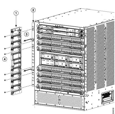
a.![]() Remove the EMI panel, which holds the lower side frame pieces, by loosening the four captive screws on the EMI frame until they no longer connect with the chassis.
Remove the EMI panel, which holds the lower side frame pieces, by loosening the four captive screws on the EMI frame until they no longer connect with the chassis.
b.![]() Remove each of the two side frames from the EMI panel by loosening and removing the two screws that hold each side frame piece to the EMI panel.
Remove each of the two side frames from the EMI panel by loosening and removing the two screws that hold each side frame piece to the EMI panel.
c.![]() Reattach the EMI panel to the chassis by placing the EMI panel over the air intake area and aligning its captive screws to their holes in the chassis. Securely tighten each of the captive screws.
Reattach the EMI panel to the chassis by placing the EMI panel over the air intake area and aligning its captive screws to their holes in the chassis. Securely tighten each of the captive screws.
d.![]() Remove each of the two front doors by loosening and removing the four screws that hold each door frame to the chassis.
Remove each of the two front doors by loosening and removing the four screws that hold each door frame to the chassis.
e.![]() Remove the bottom frame by loosening and removing the three screws on the frame.
Remove the bottom frame by loosening and removing the three screws on the frame.
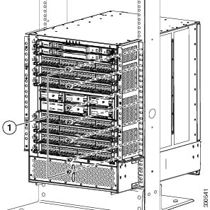
Step 9![]() Loosen and remove the 6 screws that hold each side of the chassis (12 screws total) to the vertical mounting rails on the rack or cabinet.
Loosen and remove the 6 screws that hold each side of the chassis (12 screws total) to the vertical mounting rails on the rack or cabinet.
Step 10![]() Position a mechanical lift in front of the chassis and raise its platform to the bottom of the chassis (no more than 0.25 inches (0.6 cm) below the bottom of the chassis), so that you can push the chassis onto the lift platform.
Position a mechanical lift in front of the chassis and raise its platform to the bottom of the chassis (no more than 0.25 inches (0.6 cm) below the bottom of the chassis), so that you can push the chassis onto the lift platform.
Step 11![]() Lay the shipping pallet flat on the floor. This pallet includes a raised portion that is bolted to the larger pallet. Make sure that the raised portion is on top.
Lay the shipping pallet flat on the floor. This pallet includes a raised portion that is bolted to the larger pallet. Make sure that the raised portion is on top.
Step 12![]() Use at least four persons to push the chassis onto the mechanical lift.
Use at least four persons to push the chassis onto the mechanical lift.
Step 13![]() After you securely position the chassis on the mechanical lift, use the mechanical lift to move the chassis to its pallet.
After you securely position the chassis on the mechanical lift, use the mechanical lift to move the chassis to its pallet.
Step 14![]() Lower the chassis to the level of the pallet or no more than 0.25 inches (0.6 cm) above the pallet.
Lower the chassis to the level of the pallet or no more than 0.25 inches (0.6 cm) above the pallet.
Step 15![]() Use at least four persons to push the chassis onto the raised portion of the pallet. Position the chassis so that it is 4 inches (10.2 cm) away from the side of the common edge of the pallet and its raised portion.
Use at least four persons to push the chassis onto the raised portion of the pallet. Position the chassis so that it is 4 inches (10.2 cm) away from the side of the common edge of the pallet and its raised portion.
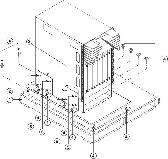
Step 16![]() Attach two angle brackets to the raised portion of the pallet between the chassis and the pallet edge. Do not tighten the screws that hold these brackets to the pallet—you will need to adjust their placement after you place the chassis on the pallet. See Figure E-16.
Attach two angle brackets to the raised portion of the pallet between the chassis and the pallet edge. Do not tighten the screws that hold these brackets to the pallet—you will need to adjust their placement after you place the chassis on the pallet. See Figure E-16.
Figure E-16 Attaching the Chassis to the Shipping Pallet
|
|
|
||
|
|
|
||
|
|
Mounting brackets (two shown and two hidden on the other side of the chassis) |
|
Step 17![]() Align the screw holes in the side of the chassis with the screw holes in the vertical sides of the two angle brackets. Fasten the two angle brackets to the chassis by securely tightening the four screws for each bracket. See Figure E-16.
Align the screw holes in the side of the chassis with the screw holes in the vertical sides of the two angle brackets. Fasten the two angle brackets to the chassis by securely tightening the four screws for each bracket. See Figure E-16.
Step 18![]() Attach two more angle brackets to the pallet on the other side of the chassis. Make sure that the four screw holes on the vertical side of each bracket align with four holes in the chassis.
Attach two more angle brackets to the pallet on the other side of the chassis. Make sure that the four screw holes on the vertical side of each bracket align with four holes in the chassis.
Step 19![]() Use four screws to securely attach each of the additional two brackets to the chassis.
Use four screws to securely attach each of the additional two brackets to the chassis.
Step 20![]() Securely fasten the two bolts on each of the four angle brackets to the pallet.
Securely fasten the two bolts on each of the four angle brackets to the pallet.
Step 21![]() Place the packing bag over the chassis.
Place the packing bag over the chassis.
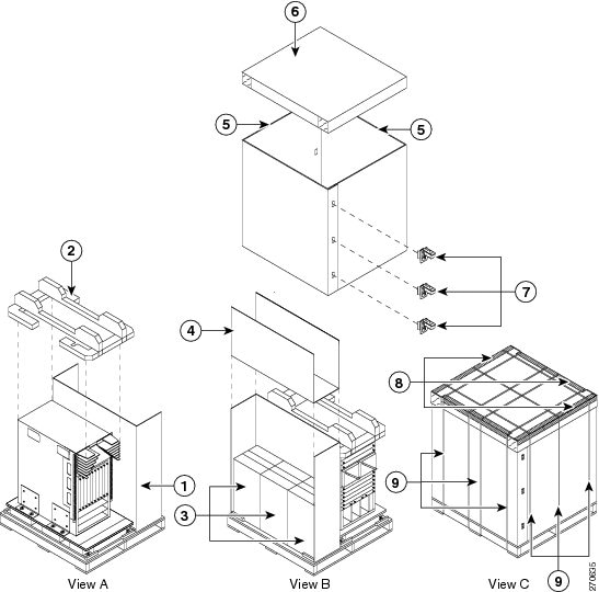
Step 22![]() Place the chassis packing cushion on top of the bagged chassis as shown in View A in Figure E-17.
Place the chassis packing cushion on top of the bagged chassis as shown in View A in Figure E-17.
Figure E-17 Packing the System Components
|
|
|
||
|
|
|
||
|
|
Power supply box (one box for three power supply units or three boxes for three units) |
|
|
|
|
|
||
|
|
|
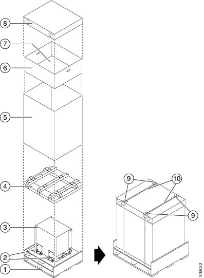
Step 23![]() Place the larger of the two three-segment dividers beside the chassis (see Callout 1 in Figure E-17).
Place the larger of the two three-segment dividers beside the chassis (see Callout 1 in Figure E-17).
Step 24![]() Place the multi-unit power supply box (or three single-unit power supply boxes [one or more can be empty]) in the empty area beside the chassis (see Callout 3 in Figure E-17).
Place the multi-unit power supply box (or three single-unit power supply boxes [one or more can be empty]) in the empty area beside the chassis (see Callout 3 in Figure E-17).
Step 25![]() Place the smaller three-segment divider in the empty area above the power supply boxes (see Callout 4 in Figure E-17).
Place the smaller three-segment divider in the empty area above the power supply boxes (see Callout 4 in Figure E-17).
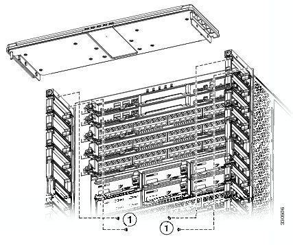
Step 26![]() Remove each of the two bottom-support rails from the rack or cabinet by loosening the six screws that secure it to the vertical mounting rails on the rack or cabinet.
Remove each of the two bottom-support rails from the rack or cabinet by loosening the six screws that secure it to the vertical mounting rails on the rack or cabinet.
Step 27![]() Reassemble the accessory kit by placing the following components in the accessory kit box:
Reassemble the accessory kit by placing the following components in the accessory kit box:
- Bottom-support rails (two) and mounting screws (20)
- Console connector cables and adapters
- Ground lugs and mounting screws (two per lug)
- Power cables (one or two for each power supply)
Step 28![]() Place the accessory kit box on top of the cushion that is located on top of the chassis.
Place the accessory kit box on top of the cushion that is located on top of the chassis.
Step 29![]() If your system included the optional midframe doors or air filter, pack those items in their original shipping boxes and place the boxes on top of the power supply boxes.
If your system included the optional midframe doors or air filter, pack those items in their original shipping boxes and place the boxes on top of the power supply boxes.
Step 30![]() Place one J-box half on the bottom pallet along two sides of the pallet (see Callout 5 in Figure E-17).
Place one J-box half on the bottom pallet along two sides of the pallet (see Callout 5 in Figure E-17).
Step 31![]() Place the other J-box half on the other two sides (see Callout 5 in Figure E-17).
Place the other J-box half on the other two sides (see Callout 5 in Figure E-17).
Step 32![]() Connect the two J-box pieces with six corro clips (three on each seam) (see Callout 7 in Figure E-17).
Connect the two J-box pieces with six corro clips (three on each seam) (see Callout 7 in Figure E-17).
Step 33![]() Place the corrugated cardboard lid on top of the package (see Callout 6 in Figure E-17).
Place the corrugated cardboard lid on top of the package (see Callout 6 in Figure E-17).
Step 34![]() Place each of the four edge protectors on one of the top edges of the lid (see Callout 8 in Figure E-17).
Place each of the four edge protectors on one of the top edges of the lid (see Callout 8 in Figure E-17).
Step 35![]() Secure the package to the pallet using at least seven packing straps (three in one direction and four in the other direction) (see Callout 9 in Figure E-17).
Secure the package to the pallet using at least seven packing straps (three in one direction and four in the other direction) (see Callout 9 in Figure E-17).
Repacking the Cisco Nexus 7018 Switch
If you do not have the original packing materials for the Cisco Nexus 7018 switch that you are going to repack, you must order another set of these materials (order part number is N7K-C7018-SHPPKG=).
To repack the Cisco Nexus 7018 system, follow these steps:
Step 1![]() Turn the power switch on each power supply unit to STBY. The OUTPUT LED turns off.
Turn the power switch on each power supply unit to STBY. The OUTPUT LED turns off.
Step 2![]() For each AC power supply unit, remove the power cords as follows:
For each AC power supply unit, remove the power cords as follows:
a.![]() Remove the power plugs from the power source. If there are two power cables coming from the power supply unit, remove two power plugs. Otherwise remove one power plug.
Remove the power plugs from the power source. If there are two power cables coming from the power supply unit, remove two power plugs. Otherwise remove one power plug.
b.![]() If you are removing a 6-kW AC power supply unit, unscrew the screw on the cable retention device and pull one or two plugs off the power supply unit.
If you are removing a 6-kW AC power supply unit, unscrew the screw on the cable retention device and pull one or two plugs off the power supply unit.
Note![]() For a 7.5-kW power supply unit, you cannot remove the power cords from them because they are permanently attached.
For a 7.5-kW power supply unit, you cannot remove the power cords from them because they are permanently attached.
Step 3![]() For each DC power supply unit, shut off the input power and remove the power cords as follows:
For each DC power supply unit, shut off the input power and remove the power cords as follows:
a.![]() Shut off the input power by manually turning off each input circuit at its circuit breaker.
Shut off the input power by manually turning off each input circuit at its circuit breaker.
Warning![]() Before performing any of the following procedures, ensure that power is removed from the DC circuit. Statement 1003
Before performing any of the following procedures, ensure that power is removed from the DC circuit. Statement 1003
b.![]() Verify that the input power is completely off by making sure that all of the LEDs on the DC power supply units are off.
Verify that the input power is completely off by making sure that all of the LEDs on the DC power supply units are off.
c.![]() Remove the set of power cables from the DC power source or the DC PIU.
Remove the set of power cables from the DC power source or the DC PIU.
Warning![]() Hazardous voltage or energy may be present on DC power terminals. Always replace cover when terminals are not in service. Be sure uninsulated conductors are not accessible when cover is in place. Statement 1075
Hazardous voltage or energy may be present on DC power terminals. Always replace cover when terminals are not in service. Be sure uninsulated conductors are not accessible when cover is in place. Statement 1075
d.![]() Unscrew the two screws that secure each of the power plugs to the power supply unit.
Unscrew the two screws that secure each of the power plugs to the power supply unit.
e.![]() Unplug each of the power plugs from the power supply unit.
Unplug each of the power plugs from the power supply unit.
f.![]() Disconnect the power supply grounding cable by unscrewing its two M6 nuts and removing the grounding lug from the power supply unit. For the location of the DC power supply unit grounding pad, see Figure 6-2.
Disconnect the power supply grounding cable by unscrewing its two M6 nuts and removing the grounding lug from the power supply unit. For the location of the DC power supply unit grounding pad, see Figure 6-2.
Warning![]() When installing or replacing the unit, the ground connection must always be made first and disconnected last. Statement 1046
When installing or replacing the unit, the ground connection must always be made first and disconnected last. Statement 1046
Step 4![]() For each AC power supply unit, remove the power supply unit and repack it as follows:
For each AC power supply unit, remove the power supply unit and repack it as follows:
Note![]() These instructions are for the multi-unit power supply box that comes with newer Cisco Nexus 7018 switches. If you have the single-unit box for the 6-kW AC power supply unit, see Figure 10-1 for packing instructions.
These instructions are for the multi-unit power supply box that comes with newer Cisco Nexus 7018 switches. If you have the single-unit box for the 6-kW AC power supply unit, see Figure 10-1 for packing instructions.
a.![]() Open the box for the power supply units and make sure that the cardboard holders are set up inside the box (see Callout 1 in Figure E-18).
Open the box for the power supply units and make sure that the cardboard holders are set up inside the box (see Callout 1 in Figure E-18).
Figure E-18 Packing AC Power Supply Units in a Cisco Nexus 7018 Multi-Unit Box
b.![]() Make sure there is a packing cushion below the cardboard holder (see Callout 2 in Figure E-18).
Make sure there is a packing cushion below the cardboard holder (see Callout 2 in Figure E-18).
c.![]() Loosen the four captive screws on the power supply unit so that they no longer connect with the chassis.
Loosen the four captive screws on the power supply unit so that they no longer connect with the chassis.
d.![]() With one hand on the handle of the power supply unit, pull the unit partially out of the chassis.
With one hand on the handle of the power supply unit, pull the unit partially out of the chassis.
e.![]() Place your other hand underneath the power supply unit to support the unit, and then pull the unit fully out of the chassis.
Place your other hand underneath the power supply unit to support the unit, and then pull the unit fully out of the chassis.
f.![]() Place the power supply unit in an ESD packing bag and insert the bagged power supply unit in one of the larger slots in the packing box (see Callout 3 in Figure E-18).
Place the power supply unit in an ESD packing bag and insert the bagged power supply unit in one of the larger slots in the packing box (see Callout 3 in Figure E-18).
Note![]() For easier handling of a multi-unit box, arrange the power supply units so their weight is balanced in the box. If you are packing only one unit, place it in the middle of the box. If you are packing two units, place them in the large slots at each end of the box. If you are packing three units, place one in the middle of the box and the other two in slots at either end of the box.
For easier handling of a multi-unit box, arrange the power supply units so their weight is balanced in the box. If you are packing only one unit, place it in the middle of the box. If you are packing two units, place them in the large slots at each end of the box. If you are packing three units, place one in the middle of the box and the other two in slots at either end of the box.
g.![]() Coil the power cables and insert them in the slots next to the power supply unit (see Callout 4 in Figure E-18).
Coil the power cables and insert them in the slots next to the power supply unit (see Callout 4 in Figure E-18).
h.![]() If there is another AC power supply unit to repack, repeat Steps 4b through 4g.
If there is another AC power supply unit to repack, repeat Steps 4b through 4g.
i.![]() Place the packing cushion above the power supply units (see Callout 5 in Figure E-18.
Place the packing cushion above the power supply units (see Callout 5 in Figure E-18.
j.![]() Fold the narrow flaps of the box over the top pad (see Callout 6 in Figure E-18).
Fold the narrow flaps of the box over the top pad (see Callout 6 in Figure E-18).
k.![]() Fold the wide flaps over the folded narrow flaps (see Callout 7 in Figure E-18).
Fold the wide flaps over the folded narrow flaps (see Callout 7 in Figure E-18).
l.![]() Tape the wide flaps together and to the box (see Callout 8 in Figure E-18).
Tape the wide flaps together and to the box (see Callout 8 in Figure E-18).
Step 5![]() For the DC power supply units, repack them as follows:
For the DC power supply units, repack them as follows:
a.![]() Open the four-unit packing box and place one or two coiled power cables on the bottom of the box (see Callout 1 in Figure E-19).
Open the four-unit packing box and place one or two coiled power cables on the bottom of the box (see Callout 1 in Figure E-19).
Figure E-19 Packing a 6-kW DC Power Supply Unit in a Single-Unit Box
b.![]() Fold the trifold cover at its seams and place it over the coiled power cables (see Callout 2 in Figure E-19).
Fold the trifold cover at its seams and place it over the coiled power cables (see Callout 2 in Figure E-19).
c.![]() Loosen the four captive screws on the power supply unit so that they no longer connect with the chassis.
Loosen the four captive screws on the power supply unit so that they no longer connect with the chassis.
d.![]() With one hand on the handle of the power supply unit, pull the unit partially out of the chassis.
With one hand on the handle of the power supply unit, pull the unit partially out of the chassis.
e.![]() Place your other hand underneath the power supply unit to support the unit, and then pull the unit fully out of the chassis.
Place your other hand underneath the power supply unit to support the unit, and then pull the unit fully out of the chassis.
f.![]() Place the power supply unit in an ESD packing bag and insert the bagged power supply unit in one of the larger slots in the packing box (see Callout 3 in Figure E-19).
Place the power supply unit in an ESD packing bag and insert the bagged power supply unit in one of the larger slots in the packing box (see Callout 3 in Figure E-19).
Note![]() For easier handling of a multi-unit box, arrange the power supply units so their weight is balanced in the box. If you are packing only one unit, place it in the middle of the box. If you are packing two units, place them in the large slots at each end of the box. If you are packing three units, place one in the middle of the box and the other two in slots at either end of the box. Always leave empty slots between power supply units so that you can pack their cables.
For easier handling of a multi-unit box, arrange the power supply units so their weight is balanced in the box. If you are packing only one unit, place it in the middle of the box. If you are packing two units, place them in the large slots at each end of the box. If you are packing three units, place one in the middle of the box and the other two in slots at either end of the box. Always leave empty slots between power supply units so that you can pack their cables.
g.![]() Put the DC power supply unit in an ESD bag and place the filler box in the cutout portion of the power supply unit (see Callout 3 in Figure E-19).
Put the DC power supply unit in an ESD bag and place the filler box in the cutout portion of the power supply unit (see Callout 3 in Figure E-19).
h.![]() Insert the back end of the power supply unit and filler box into a foam block (see Callout 4 in Figure E-19).
Insert the back end of the power supply unit and filler box into a foam block (see Callout 4 in Figure E-19).
i.![]() Expand the other foam block by pulling its two sides apart, and fit the block around the front of the power supply unit before bringing the two sides together again (see Callout 5 in Figure E-19).
Expand the other foam block by pulling its two sides apart, and fit the block around the front of the power supply unit before bringing the two sides together again (see Callout 5 in Figure E-19).
j.![]() Place the power supply unit and its foam blocks in the box (see Callout 6 in Figure E-19).
Place the power supply unit and its foam blocks in the box (see Callout 6 in Figure E-19).
k.![]() Fold the narrow flaps over the power supply unit (see Callout 7 in Figure E-19).
Fold the narrow flaps over the power supply unit (see Callout 7 in Figure E-19).
l.![]() Fold the wide flaps over the narrow flaps (see Callout 8 in Figure E-19).
Fold the wide flaps over the narrow flaps (see Callout 8 in Figure E-19).
m.![]() Tape the wide flaps together and to the box with packing tape (see Callout 8 in Figure E-19).
Tape the wide flaps together and to the box with packing tape (see Callout 8 in Figure E-19).
Step 6![]() Disconnect the switch from the console and the network as follows:
Disconnect the switch from the console and the network as follows:
a.![]() On each supervisor module, disconnect the cables connected to the Console, Com/AUX, Management, and CMP Management ports.
On each supervisor module, disconnect the cables connected to the Console, Com/AUX, Management, and CMP Management ports.
b.![]() Disconnect all of the cables from each of the I/O modules.
Disconnect all of the cables from each of the I/O modules.
Step 7![]() Disconnect the one or two chassis grounding connections as follows:
Disconnect the one or two chassis grounding connections as follows:
a.![]() Unscrew the two M4 screws that hold each ground lug to the chassis. For the locations of the two grounding pads on the Cisco Nexus 7010 switch, see Figure 4-6 and Figure 4-7.
Unscrew the two M4 screws that hold each ground lug to the chassis. For the locations of the two grounding pads on the Cisco Nexus 7010 switch, see Figure 4-6 and Figure 4-7.
b.![]() Place the screws in the accessory kit.
Place the screws in the accessory kit.
Step 8![]() Disconnect the switch from the network as follows:
Disconnect the switch from the network as follows:
a.![]() Disconnect the cables that attach the Management and CMP processors on each supervisor module to a console.
Disconnect the cables that attach the Management and CMP processors on each supervisor module to a console.
b.![]() Disconnect all of the I/O cables from the I/O modules.
Disconnect all of the I/O cables from the I/O modules.
Step 9![]() If the chassis includes the optional front door and air-intake frame, remove them as follows:
If the chassis includes the optional front door and air-intake frame, remove them as follows:
a.![]() Open the door by pulling one of its latch handles out until it clicks (the handle clicks when you pull it out about 30 degrees) and rotate the door away from the chassis (see Figure E-20).
Open the door by pulling one of its latch handles out until it clicks (the handle clicks when you pull it out about 30 degrees) and rotate the door away from the chassis (see Figure E-20).
Figure E-20 Removing One Side of the Front Door
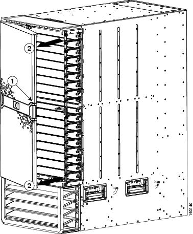
|
|
|
b.![]() Press the locking button on the back side of the door (behind the opened latch handle) so that the latch handle flattens to the front side of the door (see Figure E-21).
Press the locking button on the back side of the door (behind the opened latch handle) so that the latch handle flattens to the front side of the door (see Figure E-21).
Figure E-21 Location of the Latch Locking Button
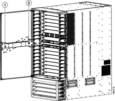
|
|
|
c.![]() Hold the opened side of the door with one hand and use your other hand to open the latch handle on the hinged side of the door until the handle clicks (see Callout 1 in Figure E-22). Use both hands to remove the door from the chassis.
Hold the opened side of the door with one hand and use your other hand to open the latch handle on the hinged side of the door until the handle clicks (see Callout 1 in Figure E-22). Use both hands to remove the door from the chassis.
Figure E-22 Removing the Front Door
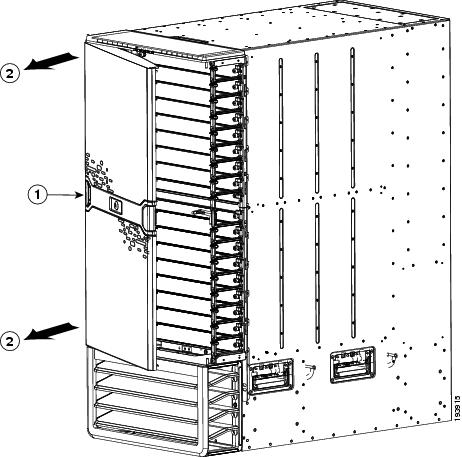
|
|
|
d.![]() Press the locking button on the inside surface of the door behind the opened latch to flatten the latch handle to the front side of the door (see Figure E-21).
Press the locking button on the inside surface of the door behind the opened latch to flatten the latch handle to the front side of the door (see Figure E-21).
e.![]() Open the box for the front door. You can find this box in the box that contains the front door and air intake frame kit. Make sure that four side cushions are aligned to the edges of the center panel of the box (see Callouts 1 and 2 in Figure E-23).
Open the box for the front door. You can find this box in the box that contains the front door and air intake frame kit. Make sure that four side cushions are aligned to the edges of the center panel of the box (see Callouts 1 and 2 in Figure E-23).
Figure E-23 Packing the Front Door
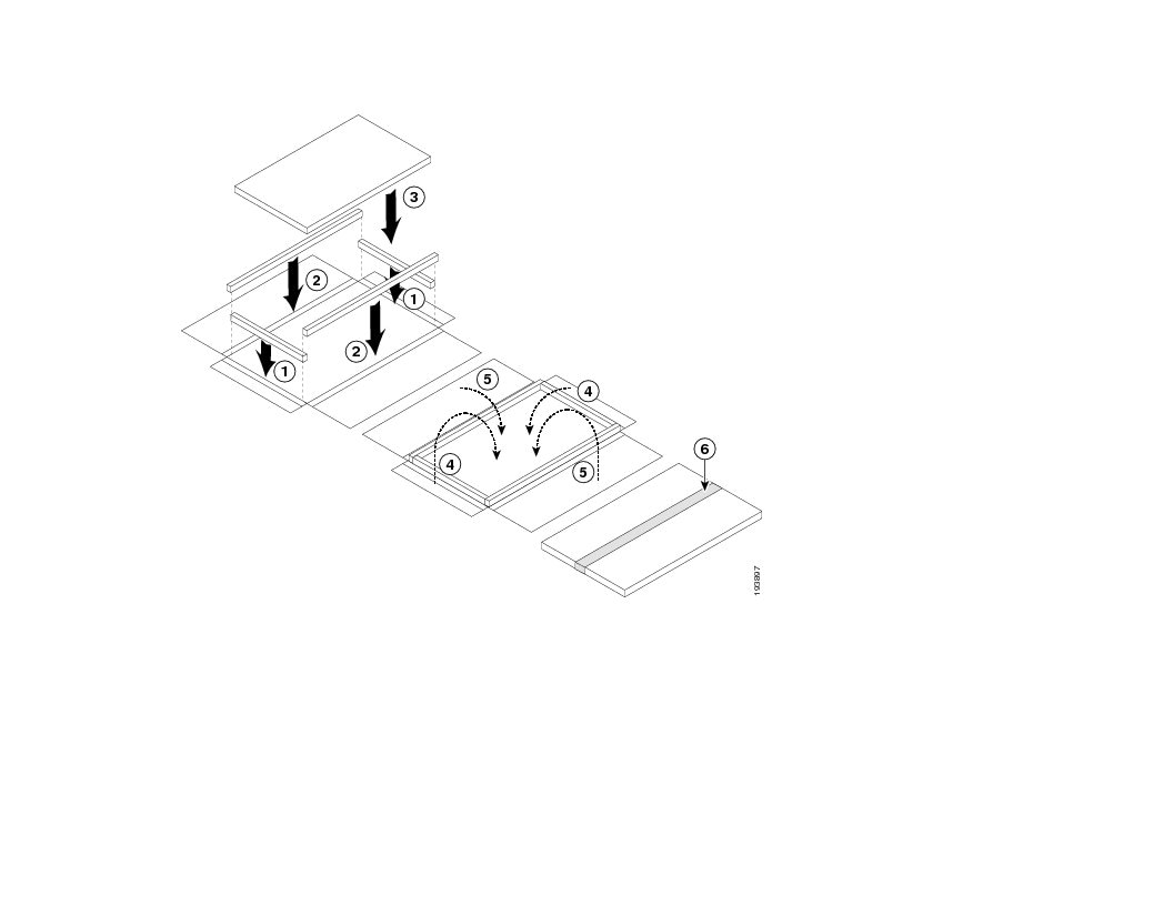
f.![]() Fold the box flaps over the door and tape them in place.
Fold the box flaps over the door and tape them in place.
g.![]() Loosen and remove the eight screws holding the bottom hinge bracket for the door. Four of the screws are attached to the right and left side of the cable management frame (two screws on each side) and four of the screws are attached to the chassis (see Figure E-24). Place the screws in a small parts bag.
Loosen and remove the eight screws holding the bottom hinge bracket for the door. Four of the screws are attached to the right and left side of the cable management frame (two screws on each side) and four of the screws are attached to the chassis (see Figure E-24). Place the screws in a small parts bag.
Note![]() Do not remove the top cover at this time. The top cover is part of the cable management frame.
Do not remove the top cover at this time. The top cover is part of the cable management frame.
Figure E-24 Removing the Bottom Hinge Bracket
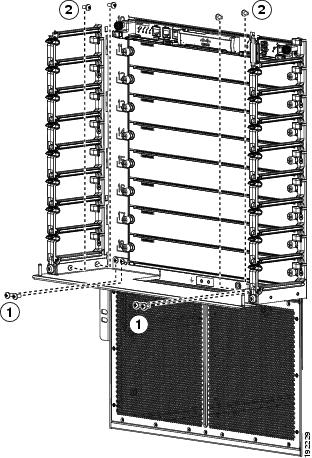
|
|
|
Remove four M4x8 screws from the cable management assemblies (two screws on each side). |
h.![]() Remove the bracket from the chassis and place it in the opened box for that bracket.
Remove the bracket from the chassis and place it in the opened box for that bracket.
i.![]() Fold the box flaps over the bracket and tape them together and to the box.
Fold the box flaps over the bracket and tape them together and to the box.
j.![]() Loosen and remove the two M3x10 screws that hold the right door stopper to the right cable management frame. Place the two screws and the door stopper in the small parts bag for the door.
Loosen and remove the two M3x10 screws that hold the right door stopper to the right cable management frame. Place the two screws and the door stopper in the small parts bag for the door.
k.![]() Loosen and remove the two M3x10 screws that hold the left door stopper to the left cable management frame. Place the two screws and the door stopper in the small parts bag for the door.
Loosen and remove the two M3x10 screws that hold the left door stopper to the left cable management frame. Place the two screws and the door stopper in the small parts bag for the door.
l.![]() Fold the short box flaps over the top, fold the long box flaps over the short flaps, and then tape the long flaps together and to the box with packing tape.
Fold the short box flaps over the top, fold the long box flaps over the short flaps, and then tape the long flaps together and to the box with packing tape.
m.![]() Loosen the two captive screws on the air intake frame (there is one captive screw on each side) so that they are no longer in contact with the chassis (see Callout 1 in Figure E-25).
Loosen the two captive screws on the air intake frame (there is one captive screw on each side) so that they are no longer in contact with the chassis (see Callout 1 in Figure E-25).
Figure E-25 Removing the Air Intake Assembly
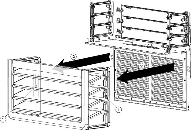
|
|
Loosen two captive screws until they are clear of the chassis. |
|
n.![]() Pull the air intake assembly off the chassis.
Pull the air intake assembly off the chassis.
o.![]() Loosen and remove the four ball-point studs shown in Figure E-26.
Loosen and remove the four ball-point studs shown in Figure E-26.
Figure E-26 Removing the Ball-Point Alignment Studs
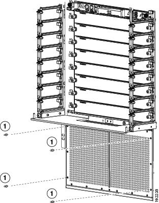
|
|
|
p.![]() Repack the air intake frame in its original packing box and put the ball-point alignment screws in the small parts bag for the door.
Repack the air intake frame in its original packing box and put the ball-point alignment screws in the small parts bag for the door.
q.![]() Fold the two short box flaps over the air intake frame, fold the two long box flaps over the short flaps, and then tape the long flaps together and to the box with packing tape.
Fold the two short box flaps over the air intake frame, fold the two long box flaps over the short flaps, and then tape the long flaps together and to the box with packing tape.
r.![]() Open the box for the front door and air intake frame kit and insert the components (see Callout 1 in Figure E-27).
Open the box for the front door and air intake frame kit and insert the components (see Callout 1 in Figure E-27).
Figure E-27 Packaging the Front Door and Air Intake Frame Kit
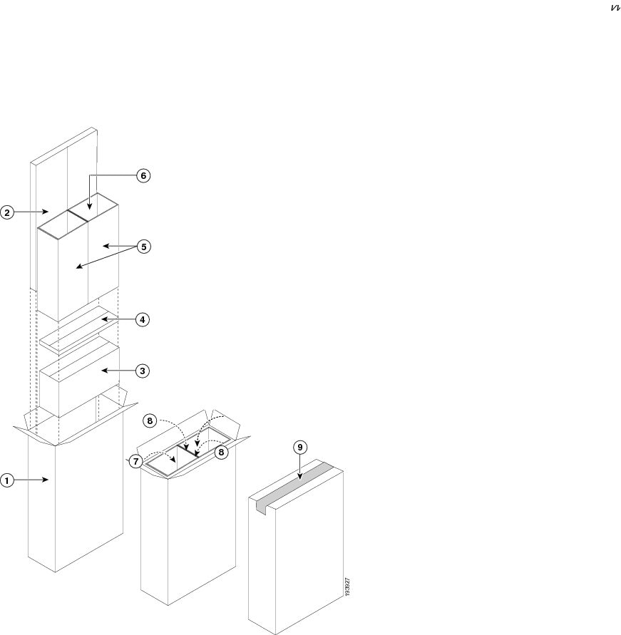
Step 10![]() Remove and repack the cable management system by following these steps:
Remove and repack the cable management system by following these steps:
a.![]() Loosen and remove the eight M4x8 pan-head screws that fasten the top cover to the upper cable management assemblies and chassis (see Figure E-28).
Loosen and remove the eight M4x8 pan-head screws that fasten the top cover to the upper cable management assemblies and chassis (see Figure E-28).
Figure E-28 Detaching the Top Cover from the Upper-Cable-Management Assemblies and Chassis
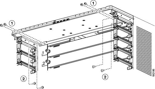
|
|
|
Four M4x8 pan-head screws fastened to the two upper cable management assemblies |
b.![]() Remove the top cover from the chassis and the two upper cable management assemblies.
Remove the top cover from the chassis and the two upper cable management assemblies.
c.![]() For the upper cable management assembly on the left, loosen and remove five M4x10 screws, and then lift off the assembly as shown in Figure E-29.
For the upper cable management assembly on the left, loosen and remove five M4x10 screws, and then lift off the assembly as shown in Figure E-29.
d.![]() Repeat Step 3c for the upper cable management assembly on the right side.
Repeat Step 3c for the upper cable management assembly on the right side.
Figure E-29 Removing an Upper-Cable-Management Assembly
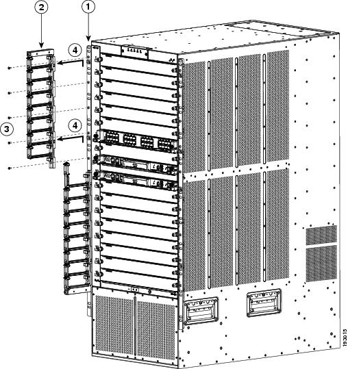
|
|
|
||
|
|
|
Lift the upper cable management assembly off the rack-mount bracket hooks. |
e.![]() For the lower cable management assembly on the left, loosen and remove four M4x10 screws, and then lift off the assembly as shown in Figure E-30.
For the lower cable management assembly on the left, loosen and remove four M4x10 screws, and then lift off the assembly as shown in Figure E-30.
Figure E-30 Removing a Lower Cable Management Assembly
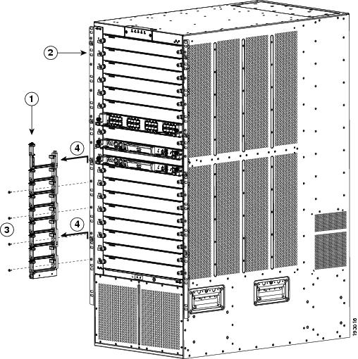
|
|
|
||
|
|
|
Lift the lower cable management assembly off the rack-mount bracket hooks. |
f.![]() Repeat Step 3e for the lower cable management assembly on the right side.
Repeat Step 3e for the lower cable management assembly on the right side.
g.![]() Open the box for the cable management frames and remove the packing materials.
Open the box for the cable management frames and remove the packing materials.
h.![]() Place the packing cushion and cardboard dividers in the box as shown with Callouts 2 and 3 in Figure E-31.
Place the packing cushion and cardboard dividers in the box as shown with Callouts 2 and 3 in Figure E-31.
Figure E-31 Packing the Cisco Nexus 7018 Cable Management System
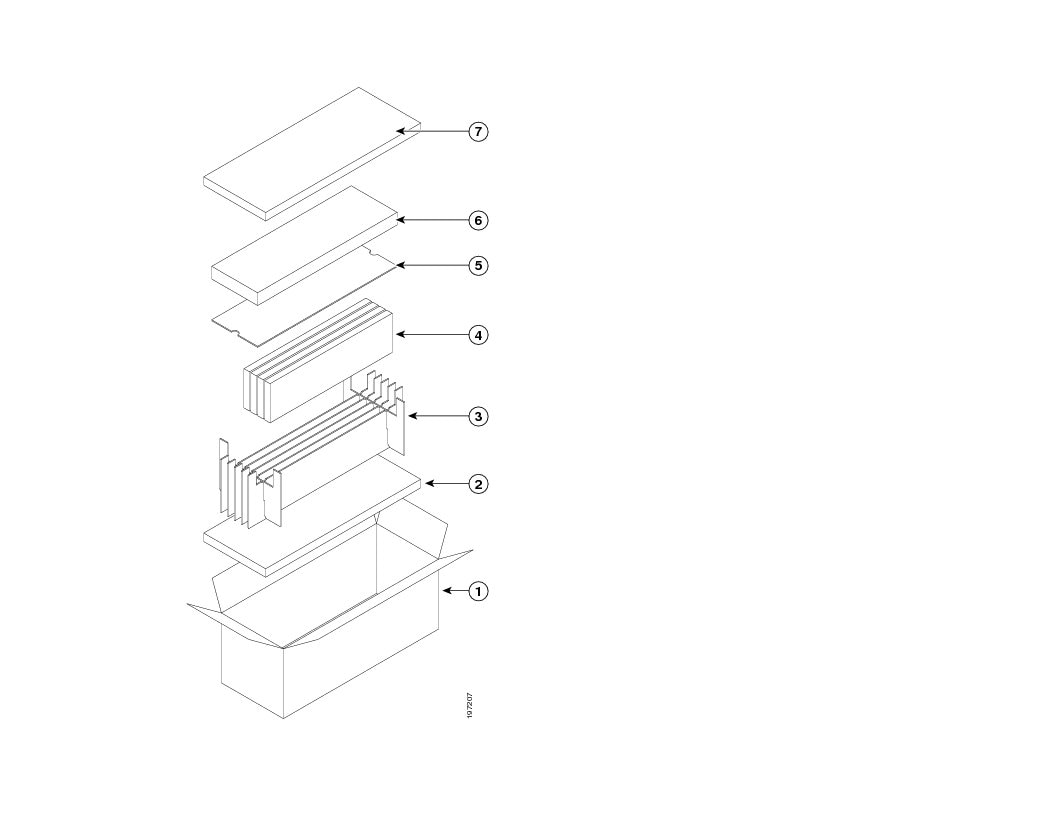
|
|
|
Place the flat cardboard divider on top of the cable management frames. |
|
|
|
|
||
|
|
|
||
|
|
Insert each of four cable management frames in an open divider slot. |
|
i.![]() Insert each of the four cable management frames into one of the open slots in the cardboard dividers.
Insert each of the four cable management frames into one of the open slots in the cardboard dividers.
j.![]() Place the flat cardboard divider on top of the packed cable management frames (see Callout 5 in Figure E-31).
Place the flat cardboard divider on top of the packed cable management frames (see Callout 5 in Figure E-31).
k.![]() Open the box for the top cover, place the top cover in the box, close the box, and place the box on top of the flat cardboard piece, which covers the packed cable management frames (see Callout 6 in Figure E-31).
Open the box for the top cover, place the top cover in the box, close the box, and place the box on top of the flat cardboard piece, which covers the packed cable management frames (see Callout 6 in Figure E-31).
l.![]() Place the remaining packing cushion on top of the top cover box, close the box for the cable management frames, and tape it shut.
Place the remaining packing cushion on top of the top cover box, close the box for the cable management frames, and tape it shut.
Step 11![]() If you need to make the chassis as light as possible for moving, remove the fan trays as follows:
If you need to make the chassis as light as possible for moving, remove the fan trays as follows:
a.![]() Place an antistatic mat or antistatic foam where you can place two fan trays.
Place an antistatic mat or antistatic foam where you can place two fan trays.
b.![]() Choose a place that prevents damage to the fan trays while they are outside the chassis.
Choose a place that prevents damage to the fan trays while they are outside the chassis.
c.![]() Unpack and place the replacement fan tray on the antistatic mat or antistatic foam.
Unpack and place the replacement fan tray on the antistatic mat or antistatic foam.
d.![]() Loosen the four captive screws on the fan tray that you are replacing by turning them counterclockwise until they are free of the chassis.
Loosen the four captive screws on the fan tray that you are replacing by turning them counterclockwise until they are free of the chassis.
e.![]() Grasp the fan tray handle with one hand and pull the fan tray part way out of its slot on the chassis.
Grasp the fan tray handle with one hand and pull the fan tray part way out of its slot on the chassis.
f.![]() If the fan tray power connector does not easily unseat from the backplane, rock it gently.
If the fan tray power connector does not easily unseat from the backplane, rock it gently.
g.![]() Place a hand under the bottom side of the fan tray to support it and pull the fan tray out of the chassis.
Place a hand under the bottom side of the fan tray to support it and pull the fan tray out of the chassis.
h.![]() Place the fan tray on an antistatic pad or repack it in its original packing materials.
Place the fan tray on an antistatic pad or repack it in its original packing materials.
Step 12![]() Disconnect each system ground by loosening and removing the two M4 screws that attach the grounding cable to the chassis.
Disconnect each system ground by loosening and removing the two M4 screws that attach the grounding cable to the chassis.
Step 13![]() Loosen and remove the 9 screws that hold each side of the chassis (18 screws total) to the vertical mounting rails on the rack or cabinet.
Loosen and remove the 9 screws that hold each side of the chassis (18 screws total) to the vertical mounting rails on the rack or cabinet.
Step 14![]() Position a mechanical lift in front of the chassis and raise its platform to the bottom of the chassis (or no more than 0.25 inches (0.6 cm) below the bottom of the chassis), so that you can push the chassis onto the lift platform.
Position a mechanical lift in front of the chassis and raise its platform to the bottom of the chassis (or no more than 0.25 inches (0.6 cm) below the bottom of the chassis), so that you can push the chassis onto the lift platform.
Step 15![]() Lay the shipping pallet flat on the floor. This pallet includes a raised portion that is bolted to the larger pallet. Make sure that the raised portion is on top.
Lay the shipping pallet flat on the floor. This pallet includes a raised portion that is bolted to the larger pallet. Make sure that the raised portion is on top.
Step 16![]() Use at least two persons to push the chassis onto the mechanical lift.
Use at least two persons to push the chassis onto the mechanical lift.
Step 17![]() After you securely position the chassis on the mechanical lift, use the mechanical lift to move the chassis to its pallet.
After you securely position the chassis on the mechanical lift, use the mechanical lift to move the chassis to its pallet.
Step 18![]() Lower the chassis to the level of the pallet or no more than 0.25 inches (0.6 cm) above the pallet.
Lower the chassis to the level of the pallet or no more than 0.25 inches (0.6 cm) above the pallet.
Step 19![]() Use at least two persons to push the chassis onto the raised portion of the pallet. Position the chassis so that it is 4 inches (10.2 cm) away from the side of the common edge of the pallet and its raised portion.
Use at least two persons to push the chassis onto the raised portion of the pallet. Position the chassis so that it is 4 inches (10.2 cm) away from the side of the common edge of the pallet and its raised portion.
Step 20![]() Attach two angle brackets to the raised portion of the pallet between the chassis and the pallet edge. Do not tighten the screws that hold these brackets to the pallet—you will need to adjust their placement after you place the chassis on the pallet. See Figure E-32.
Attach two angle brackets to the raised portion of the pallet between the chassis and the pallet edge. Do not tighten the screws that hold these brackets to the pallet—you will need to adjust their placement after you place the chassis on the pallet. See Figure E-32.
Figure E-32 Attaching the Chassis to the Shipping Pallet
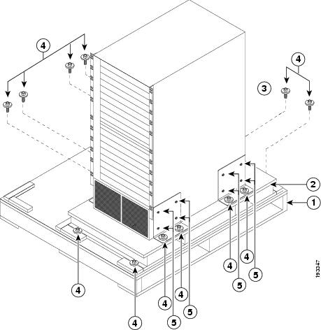
|
|
|
||
|
|
|
||
|
|
Mounting brackets (two shown and two are on the other side of the chassis) |
|
Step 21![]() Align the screw holes in the side of the chassis with the screw holes in the vertical sides of the two angle brackets. Fasten the two angle brackets to the chassis by securely tightening the four screws for each bracket. See Figure E-32.
Align the screw holes in the side of the chassis with the screw holes in the vertical sides of the two angle brackets. Fasten the two angle brackets to the chassis by securely tightening the four screws for each bracket. See Figure E-32.
Step 22![]() Attach two more angle brackets to the pallet on the other side of the chassis. Make sure that the four screw holes on the vertical side of each bracket align with four holes in the chassis.
Attach two more angle brackets to the pallet on the other side of the chassis. Make sure that the four screw holes on the vertical side of each bracket align with four holes in the chassis.
Step 23![]() Use four screws to securely attach each of the additional two brackets to the chassis.
Use four screws to securely attach each of the additional two brackets to the chassis.
Step 24![]() Securely fasten the two bolts on each of the four angle brackets to the pallet.
Securely fasten the two bolts on each of the four angle brackets to the pallet.
Step 25![]() If you removed the fan trays, replace them in the chassis as follows:
If you removed the fan trays, replace them in the chassis as follows:
a.![]() Hold the fan tray handle with one hand and use your other hand to hold the bottom of the fan tray.
Hold the fan tray handle with one hand and use your other hand to hold the bottom of the fan tray.
b.![]() Position the back of the fan tray to the open fan tray slot and slide the fan tray all the way into the slot until the electrical connector seats in the backplane and the captive screws are aligned to their holes in the chassis.
Position the back of the fan tray to the open fan tray slot and slide the fan tray all the way into the slot until the electrical connector seats in the backplane and the captive screws are aligned to their holes in the chassis.
c.![]() Tighten the captive screws to 8 in-lb (0.9 N·m) of torque.
Tighten the captive screws to 8 in-lb (0.9 N·m) of torque.
d.![]() Repeat Steps 25a to 25c to replace the other fan tray.
Repeat Steps 25a to 25c to replace the other fan tray.
Step 26![]() Place the packing bag over the chassis.
Place the packing bag over the chassis.
Step 27![]() Place the chassis packing cushion on top of the bagged chassis as shown in View A in Figure E-33.
Place the chassis packing cushion on top of the bagged chassis as shown in View A in Figure E-33.
Figure E-33 Packing the System Components
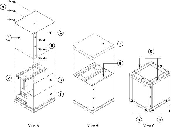
|
|
|
Insert accessory kit, cable management frame kit, and the optional front door and air intake frame kit. |
|
|
|
|
||
|
|
|
||
|
|
|
||
|
|
|
Step 28![]() Place the power supply box in the non raised area beside the chassis as shown in View A in Figure E-33.
Place the power supply box in the non raised area beside the chassis as shown in View A in Figure E-33.
Step 29![]() Place the three-segment divider in the non-raised area above the power supply box as shown in View A in Figure E-33.
Place the three-segment divider in the non-raised area above the power supply box as shown in View A in Figure E-33.
Step 30![]() Remove each of the two bottom-support rails from the rack or cabinet by loosening the eight screws that secure each of them to the vertical mounting rails on the rack or cabinet.
Remove each of the two bottom-support rails from the rack or cabinet by loosening the eight screws that secure each of them to the vertical mounting rails on the rack or cabinet.
Step 31![]() Reassemble the accessory kit by placing the following components in the accessory kit box:
Reassemble the accessory kit by placing the following components in the accessory kit box:
- Bottom-support rails (two) and mounting screws (34)
- Console connector cables and adapters
- Ground lugs (do not include the ground cable) and mounting screws (two per lug)
- Power cables (one or two for each 6-kW power supply unit)
Step 32![]() Place one J-box half on the bottom pallet along two sides of the pallet as shown in View A of Figure E-33.
Place one J-box half on the bottom pallet along two sides of the pallet as shown in View A of Figure E-33.
Step 33![]() Place the other J-box half on the other two sides as shown in View A of Figure E-33.
Place the other J-box half on the other two sides as shown in View A of Figure E-33.
Step 34![]() Connect the two J-box pieces with six corro clips (three on each seam) as shown in View A of Figure E-33.
Connect the two J-box pieces with six corro clips (three on each seam) as shown in View A of Figure E-33.
Step 35![]() If your system included the optional front door and air intake frame, pack those items in their original packing materials and place them in the open area above the power supply box.
If your system included the optional front door and air intake frame, pack those items in their original packing materials and place them in the open area above the power supply box.
Step 36![]() Place the corrugated cardboard lid on top of the package as shown in View B of Figure E-33.
Place the corrugated cardboard lid on top of the package as shown in View B of Figure E-33.
Step 37![]() Place each of the four edge protectors on one of the top edges of the lid (see View C of Figure E-33).
Place each of the four edge protectors on one of the top edges of the lid (see View C of Figure E-33).
Step 38![]() Secure the package to the pallet using at least four packing straps (two in one direction and two in the other direction) as shown in View C of Figure E-33.
Secure the package to the pallet using at least four packing straps (two in one direction and two in the other direction) as shown in View C of Figure E-33.
 Feedback