- Cisco MDS 9000 Series IP Services Configuration Guide, Release 8.x
- New and Changed Information
- Preface
- Overview
- Configuring FCIP
- Configuring the SAN Extension Tuner
- Configuring iSCSI
- Configuring IP Services
- Configuring IP Storage Services
- Configuring IPv4 for Gigabit Ethernet Interfaces
- Configuring IPv6
- Index
- Feature Information
- Overview of FCIP
- Configuring FCIP
- Enabling FCIP
- Basic FCIP Configuration
- Advanced FCIP Profile Configuration
- Advanced FCIP Interface Configuration
- Configuring Peer Information
- Configuring E Ports
- Displaying FCIP Interface Information
- Advanced FCIP Features
- FCIP Write Acceleration
- Configuring FCIP Write Acceleration
- Displaying Write Acceleration Activity Information
- FCIP Tape Acceleration
- Configuring FCIP Tape Acceleration
- Displaying Tape Acceleration Activity Information
- FCIP Compression
- Configuring FCIP Compression
- Displaying FCIP Compression Information
- Configuring FCIP Links for Maximum Performance
- Verifying FCIP Configuration
- Default Settings for FCIP Parameters
Configuring Fibre Channel over IP
Cisco MDS 9000 Family IP Storage (IPS) services extend the reach of Fibre Channel SANs by using open-standard, IP-based technology. The switch can connect separated SAN islands using Fibre Channel over IP (FCIP).

Note![]() FCIP is supported on Fibre Channel module with IPS ports on Cisco 24/10 port SAN Extension Module on Cisco MDS 9700 Series switches, MDS 9250i Multiservice Fabric Switch, and MDS 9220i Fabric Switch.
FCIP is supported on Fibre Channel module with IPS ports on Cisco 24/10 port SAN Extension Module on Cisco MDS 9700 Series switches, MDS 9250i Multiservice Fabric Switch, and MDS 9220i Fabric Switch.
This chapter includes the following sections:
Feature Information
This section briefly describes the new and updated features for releases.
Overview of FCIP
The Fibre Channel over IP Protocol (FCIP) is a tunneling protocol that connects geographically distributed Fibre Channel storage area networks (SAN islands) transparently over IP local area networks (LANs), metropolitan area networks (MANs), and wide area networks (WANs). The switch can connect separated SAN islands using Fibre Channel over IP (FCIP). (See Figure 2-1).
Figure 2-1 Fibre Channel SANs Connected by FCIP
FCIP uses TCP as a network layer transport. The DF bit is set in the TCP header.
Note![]() For more information about FCIP protocols, refer to the IETF standards for IPStorage at http://www.ietf.org. Also refer to the Fibre Channel standards for switch backbone connection at http://www.t11.org (see FC-BB-2).
For more information about FCIP protocols, refer to the IETF standards for IPStorage at http://www.ietf.org. Also refer to the Fibre Channel standards for switch backbone connection at http://www.t11.org (see FC-BB-2).
FCIP Concepts
To configure Fibre Channel module with IPS ports for FCIP, you should have a basic understanding of the following concepts:
FCIP and VE Ports
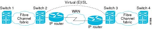
Figure 2-2 shows the internal model of FCIP in relation to Fibre Channel Inter-Switch Links (ISLs) and Cisco’s extended ISLs (EISLs).
FCIP virtual E (VE) ports operate exactly like standard Fibre Channel E ports, except that the transport in this case is FCIP instead of Fibre Channel. The only requirement is for the other end of the VE port to be another VE port.
A virtual ISL is established over an FCIP link and transports Fibre Channel traffic. Each associated virtual ISL looks like a Fibre Channel ISL with either an E port or a TE port at each end (see Figure 2-2).
Figure 2-2 FCIP Links and Virtual ISLs
See the “Configuring E Ports” section for more information.
FCIP Links
Note![]() In-order delivery (IOD) is not supported on FCIP ISLs where WA and TA are enabled.
In-order delivery (IOD) is not supported on FCIP ISLs where WA and TA are enabled.
FCIP links consist of one or more TCP connections between two FCIP link endpoints. Each link carries encapsulated Fibre Channel frames.
When the FCIP link comes up, the VE ports at both ends of the FCIP link create a virtual Fibre Channel (E)ISL and initiate the E port protocol to bring up the (E)ISL.
By default, the FCIP feature on any Cisco MDS 9000 Family switch creates two TCP connections for each FCIP link:
- One connection is used for data frames.
- The other connection is used only for Fibre Channel control frames, that is, switch-to-switch protocol frames (all Class F). This arrangement provides low latency for all control frames.
To enable FCIP on the Fibre Channel module with IPS ports, an FCIP profile and FCIP interface (interface FCIP) must be configured.
The FCIP link is established between two peers, the VE port initialization operation is identical to a normal E port. This operation is independent of the link being FCIP or pure Fibre Channel, and is based on the E port discovery process (ELP, ESC).
Once the FCIP link is established, the VE port operation is identical to E port operation for all inter-switch communication (including domain management, zones, and VSANs). At the Fibre Channel layer, all VE and E port operations are identical.
FCIP Profiles
The FCIP profile contains information about the local IP address and TCP parameters. The profile defines the following information:
- The local connection points (IP address and TCP port number)
- The operation of the underlying TCP connections for all FCIP links that use this profile
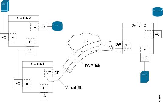
The FCIP profile’s local IP address determines the IPStorage port where the FCIP links terminate (see Figure 2-3).
Figure 2-3 FCIP Profile and FCIP Link

FCIP Interfaces
The FCIP interface is the local endpoint of the FCIP link and a VE port interface. All the FCIP and E port parameters are configured in context to the FCIP interface.
FCIP High-Availability Solutions
The following high-availability solutions are available for FCIP configurations:
Fibre Channel Port Channels
Port channels comprised of FCIP interfaces behave the same way as Fibre Channel port channels. They offer the same benefits of link redundancy between Fibre Channel switches as native FC port channels. Beneath the FCIP level, an FCIP link can run on top of a IPStorage port. This link is totally transparent to the Fibre Channel layer.
The Fibre Channel Port Channel (to which FCIP link can be a part of) does not have a restriction on which (E)ISL links can be combined in a Fibre Channel Port Channel as long as it passes the compatibility check.
For information, see the Cisco Fabric Manager Interfaces Configuration Guide and Cisco MDS 9000 Family NX-OS Interfaces Configuration Guide.
The maximum number of Fibre Channel ports that can be put into a Fibre Channel Port Channel is 16.
To configure Fibre Channel Port Channels, see the Cisco MDS 9000 Family NX-OS Interfaces Configuration Guide and Cisco Fabric Manager Interfaces Configuration Guide.
Figure 2-4 provides an example of a port channel-based load-balancing configuration. To perform this configuration, you need two IP addresses on each SAN island. This solution addresses link failures.
Figure 2-4 Port Channel-Based Load Balancing
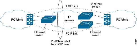
The following characteristics set Fibre Channel port channel solutions apart from other solutions:
FSPF
Figure 2-5 displays a FPSF-based load balancing configuration example. This configuration requires two IP addresses on each SAN island, and addresses IP and FCIP link failures.
Figure 2-5 FSPF-Based Load Balancing

The following characteristics set FSPF solutions apart from other solutions:
VRRP
Figure 2-6 displays a Virtual Router Redundancy Protocol (VRRP)-based high availability FCIP configuration example. This configuration requires at least two physical IPStorage ports connected to the Ethernet switch on the island where you need to implement high availability using VRRP.
Figure 2-6 VRRP-Based High Availability
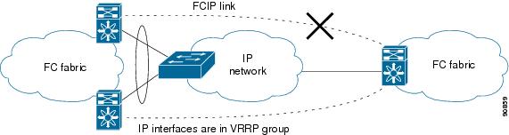
The following characteristics set VRRP solutions apart from other solutions:
- If the active VRRP port fails, the standby VRRP port takes over the VRRP IP address.
- When the VRRP switchover happens, the FCIP link automatically disconnects and reconnects.
- This configuration has only one FCIP (E)ISL link.
Note![]() Port-fast needs to be enabled in the Cisco catalyst 6500 series and Cisco Nexus 7000 series switches where the IPStorage ports or Management port is connected.
Port-fast needs to be enabled in the Cisco catalyst 6500 series and Cisco Nexus 7000 series switches where the IPStorage ports or Management port is connected.
Note![]() VRRP IPv6 is not supported for MDS 9250i switch.
VRRP IPv6 is not supported for MDS 9250i switch.
Note![]() From Cisco MDS NX-OS Release 8.3(1) and later, the VRRP feature is not supported on Cisco MDS 9000 Series Switches.
From Cisco MDS NX-OS Release 8.3(1) and later, the VRRP feature is not supported on Cisco MDS 9000 Series Switches.
Configuring FCIP
This section describes how to configure FCIP and includes the following topics:
Enabling FCIP
The Fibre Channel over IP Protocol (FCIP) is a tunneling protocol that connects geographically distributed Fibre Channel storage area networks (SAN islands) transparently over IP local area networks (LANs), metropolitan area networks (MANs), and wide area networks (WANs).
To begin configuring the FCIP feature, you must explicitly enable FCIP on the required switches in the fabric. By default, this feature is disabled in all switches in the Cisco MDS 9000 Family.
The configuration and verification operations commands for the FCIP feature are only available when FCIP is enabled on a switch. When you disable this feature, all related configurations are automatically discarded.
By default, the Cisco MDS 9700 series switches, MDS 9250i switches, and MDS 9220i switches are shipped with the SAN extension over IP package license.
To enable FCIP on any participating switch, follow these steps:
|
|
|
|
|---|---|---|
To create and manage FCIP links with DCNM-SAN, use the FCIP Wizard. For more information on the FCIP Wizard, see the Configuring FCIP chapter, in the Cisco DCNM SAN Client Online Help document.
Basic FCIP Configuration
Once you have created FCIP links using the FCIP wizard, you may need to modify parameters for these links. This includes modifying the FCIP profiles as well as the FCIP link parameters.
- For Cisco MDS 9220i Switch, each 1 Gbps or 10 Gbps IPStorage interface can have three FCIP links configured at a time and the 40 Gbps IPStorage interface can have four FCIP links configured at a time.
- For Cisco MDS 9250i Switch, each IPStorage interface can have six FCIP links configured at a time.
- For Cisco MDS 24/10-Port SAN Extension Module, each 1 Gbps or 10 Gbps IPStorage interface can have three FCIP links configured at a time and the 40 Gbps IPStorage interface can have four FCIP links configured at a time.
Note![]() When using IPsec and IKE, each IPStorage interface on the Fibre Channel module with IPS ports must be configured in its own IP subnet. If there are multiple IPStorage interfaces configured with IP address or network-mask in the same IP subnet, IKE packets might not be sent out to the correct IPS port and the IPsec link will not come up.
When using IPsec and IKE, each IPStorage interface on the Fibre Channel module with IPS ports must be configured in its own IP subnet. If there are multiple IPStorage interfaces configured with IP address or network-mask in the same IP subnet, IKE packets might not be sent out to the correct IPS port and the IPsec link will not come up.
Note![]() You can configure FCIP with IPsec and NAT on Cisco MDS 9220i switches.
You can configure FCIP with IPsec and NAT on Cisco MDS 9220i switches.
To configure an FCIP link, follow these steps on both switches:
Step 1![]() Configure the IPStorage interface.
Configure the IPStorage interface.
See the Cisco MDS 9000 Family NX-OS IP Services Configuration Guide.
Step 2![]() Create an FCIP profile and then assign the IPStorage interface’s IP address to the profile.
Create an FCIP profile and then assign the IPStorage interface’s IP address to the profile.
Step 3![]() Create an FCIP interface and then assign the profile to the interface.
Create an FCIP interface and then assign the profile to the interface.
Step 4![]() Configure the peer IP address for the FCIP interface.
Configure the peer IP address for the FCIP interface.
Creating FCIP Profiles
You must assign a local IP address of an IPStorage interface or subinterface to the FCIP profile to create an FCIP profile. You can assign IPv4 or IPv6 addresses to the interfaces. Figure 2-7 shows an example configuration.
Figure 2-7 Assigning Profiles to Each IPStorage Interface

To create an FCIP profile in switch 1 in Figure 2-7, follow these steps:
|
|
|
|
|---|---|---|
Creates a profile for the FCIP connection. The valid range is from 1 to 255. |
||
Associates the profile (10) with the local IPv4 address of the IPStorage interface (3/1). |
||
To assign an FCIP profile in switch 2 in Figure 2-7, follow these steps:
|
|
|
|
|---|---|---|
Associates the profile (20) with the local IPv4 address of the IPStorage interface. |
||
Displaying FCIP Profile Information
Example 2-1 Displaying Summary of FCIP Profiles
Example 2-2 Displaying Detailed FCIP Profile Information
Creating FCIP Links
When two FCIP link endpoints are created, an FCIP link is established between the two IPS ports. The peer IP address specifies the address of the remote FCIP endpoint. This allows the creation of an FCIP link to that peer switch once the FCIP interface is enabled.
Figure 2-8 shows an example configuration of an FCIP link.
Figure 2-8 Assigning Profiles to Each IPStorage Interface

To create an FCIP link endpoint in switch 1, follow these steps:
|
|
|
|
|---|---|---|
Assigns the peer IPv4 address information (10.1.1.1 for switch 2) to the FCIP interface. |
||
To create an FCIP link endpoint in switch 2, follow these steps:
|
|
|
|
|---|---|---|
Assigns the peer IPv4 address information (10.100.1.25 for switch 1) to the FCIP interface. |
||
Advanced FCIP Profile Configuration
A basic FCIP configuration uses the local IP address to configure the FCIP profile. In addition to the local IP address and the local port, you can specify other TCP parameters as part of the FCIP profile configuration.
This sections includes the following topics:
FCIP configuration options can be accessed from the switch (config- profile)# submode prompt.
Configuring TCP Listener Ports
To configure TCP listener ports, follow these steps:
|
|
|
|
|---|---|---|
Creates the profile (if it does not already exist) and enters profile configuration submode. The valid range is from 1 to 255. |
The default TCP port for FCIP is 3225. You can change this port by using the port command.
To change the default FCIP port number (3225), follow these steps:
|
|
|
|
|---|---|---|
Configuring TCP Parameters
You can control TCP behavior in a switch by configuring the TCP parameters that are described in this section.
Note![]() When FCIP is sent over a WAN link, the default TCP settings may not be appropriate. In such cases, we recommend that you tune the FCIP WAN link by modifying the TCP parameters (specifically bandwidth, round-trip times, and CWM burst size).
When FCIP is sent over a WAN link, the default TCP settings may not be appropriate. In such cases, we recommend that you tune the FCIP WAN link by modifying the TCP parameters (specifically bandwidth, round-trip times, and CWM burst size).
Minimum Retransmit Timeout
You can control the minimum amount of time TCP waits before retransmitting. By default, this value is 200 milliseconds.
To configure the minimum retransmit time, follow these steps:
Keepalive Timeout
You can configure the interval that the TCP connection uses to verify that the FCIP link is functioning. This ensures that an FCIP link failure is detected quickly even when there is no traffic.
If the TCP connection is idle for more than the specified time, then keepalive timeout packets are sent to ensure that the connection is active. The keepalive timeout feature can be used to tune the time taken to detect FCIP link failures.
You can configure the first interval during which the connection is idle (the default is 60 seconds). When the connection is idle for the configured interval, eight keepalive probes are sent at 1-second interval. If no response is received for these eight probes and the connection remains idle throughout, then the FCIP link is automatically closed.
Note![]() Only the first interval (during which the connection is idle) can be changed.
Only the first interval (during which the connection is idle) can be changed.
To configure the first keepalive timeout interval, follow these steps:
Maximum Retransmissions
You can specify the maximum number of times a packet is retransmitted before TCP decides to close the connection.
To configure maximum retransmissions, follow these steps:
|
|
|
|
|---|---|---|
Specifies the maximum number of retransmissions (6). The range is from 1 to 8 retransmissions. |
||
Maximum Retransmission Threshold for OBFL Logging
FCIP links utilize peer to peer TCP sessions. The intermediate network is often Ethernet which is not lossless and may drop frames. These are automatically retransmitted by the TCP sender. End applications should be able to tolerate some degree of delay caused by retransmissions. However, some applications may have a lower tolerance for retransmissions than others. Excessive TCP retransmission events are logged to OBFL to assist in troubleshooting. The threshold retransmission rate that will trigger logging can be configured. This retransmission rate is measured per FCIP profile.
To configure the OBFL retransmission rate per FCIP profile, follow these steps:
Path MTUs
Path MTU (PMTU) is the minimum MTU on the IP network between the two endpoints of the FCIP link. PMTU discovery is a mechanism by which TCP learns of the PMTU dynamically and adjusts the maximum TCP segment accordingly (RFC 1191).
By default, PMTU discovery is enabled on all switches with a timeout of 3600 seconds. If TCP reduces the size of the maximum segment because of PMTU change, the reset-timeout specifies the time after which TCP tries the original MTU.
To configure PMTU, follow these steps:
Selective Acknowledgments
TCP may experience poor performance when multiple packets are lost within one window. With the limited information available from cumulative acknowledgments, a TCP sender can only learn about a single lost packet per round trip. A selective acknowledgment (SACK) mechanism helps overcome the limitations of multiple lost packets during a TCP transmission.
The receiving TCP sends back SACK advertisements to the sender. The sender can then retransmit only the missing data segments. By default, SACK is enabled on Cisco MDS 9000 Family switches.
To configure SACK, follow these steps:
|
|
|
|
|---|---|---|
Window Management
The optimal TCP window size is automatically calculated using the maximum bandwidth parameter, the minimum available bandwidth parameter, and the dynamically measured round-trip time (RTT).
Note![]() The configured round-trip-time parameter determines the window scaling factor of the TCP connection. This parameter is only an approximation. The measured RTT value overrides the round trip time parameter for window management. If the configured round-trip-time is too small compared to the measured RTT, then the link may not be fully utilized due to the window scaling factor being too small.
The configured round-trip-time parameter determines the window scaling factor of the TCP connection. This parameter is only an approximation. The measured RTT value overrides the round trip time parameter for window management. If the configured round-trip-time is too small compared to the measured RTT, then the link may not be fully utilized due to the window scaling factor being too small.
The min-available-bandwidth parameter and the measured RTT together determine the threshold below which TCP aggressively maintains a window size sufficient to transmit at minimum available bandwidth.
The max-bandwidth-mbps parameter and the measured RTT together determine the maximum window size.
Note![]() Set the maximum bandwidth to match the worst-case bandwidth available on the physical link, considering other traffic that might be going across this link (for example, other FCIP links, WAN limitations). Maximum bandwidth should be the total bandwidth minus all other traffic going across that link.
Set the maximum bandwidth to match the worst-case bandwidth available on the physical link, considering other traffic that might be going across this link (for example, other FCIP links, WAN limitations). Maximum bandwidth should be the total bandwidth minus all other traffic going across that link.
Note![]() In Cisco MDS 9250i Multiservice Fabric Switch, you can configure the TCP maximum bandwidth up to 5 Gbps. We recommend that the minimum available bandwidth is 80% of the maximum bandwidth.
In Cisco MDS 9250i Multiservice Fabric Switch, you can configure the TCP maximum bandwidth up to 5 Gbps. We recommend that the minimum available bandwidth is 80% of the maximum bandwidth.
To configure window management, follow these steps:
Monitoring Congestion
By enabling the congestion window monitoring (CWM) parameter, you allow TCP to monitor congestion after each idle period. The CWM parameter also determines the maximum burst size allowed after an idle period. By default, this parameter is enabled and the default burst size is 50 KB.
The interaction of bandwidth parameters and CWM and the resulting TCP behavior is outlined as follows:
- If the average rate of the Fibre Channel traffic over the preceding RTT is less than the min-available-bandwidth multiplied by the RTT, the entire burst is sent immediately at the min-available-bandwidth rate, provided no TCP drops occur.
- If the average rate of the Fibre Channel traffic is greater than min-available-bandwidth multiplied by the RTT, but less than max-bandwidth multiplied by the RTT, then if the Fibre Channel traffic is transmitted in burst sizes smaller than the configured CWM value the entire burst is sent immediately by FCIP at the max-bandwidth rate.
- If the average rate of the Fibre Channel traffic is larger than the min-available-bandwidth multiplied by the RTT and the burst size is greater than the CWM value, then only a part of the burst is sent immediately. The remainder is sent with the next RTT.
The software uses standard TCP rules to increase the window beyond the one required to maintain the min-available-bandwidth to reach the max-bandwidth.

Tip![]() We recommend that this feature remains enabled to realize optimal performance. Increasing the CWM burst size can result in more packet drops in the IP network, impacting TCP performance. Only if the IP network has sufficient buffering, try increasing the CWM burst size beyond the default to achieve lower transmit latency.
We recommend that this feature remains enabled to realize optimal performance. Increasing the CWM burst size can result in more packet drops in the IP network, impacting TCP performance. Only if the IP network has sufficient buffering, try increasing the CWM burst size beyond the default to achieve lower transmit latency.
To change the CWM defaults, follow these steps:
Displaying FCIP Profile Information
Use the show fcip profile command to display FCIP profile information for the Cisco MDS 9250i Multiservice Fabric Switch:
Use the show fcip profile command to display FCIP profile information for the 24/10 port SAN Extension module:
Advanced FCIP Interface Configuration
This section describes the options you can configure on an FCIP interface to establish connection to a peer and includes the following topics:
- Assigning a Peer IP Address
- Configuring Number of TCP Connections
- Configuring Active Connections
- Enabling Time Stamp Control
- Configuring Active Connections
To establish a peer connection, you must first create the FCIP interface and enter the c onfig-if submode.
To enter the c onfig-if submode, follow these steps:
|
|
|
|
|---|---|---|
Each IPStorage interface can have three FCIP links configured at a time. For Cisco MDS 9250i, each IPStorage port can have six FCIP links configured at a time. For Cisco MDS 24/10-Port SAN Extension Module, each IPStorage port can have three FCIP links configured at a time.
Configuring Peers
All the FCIP and E port parameters are configured in context to the FCIP interface. To create an FCIP link, assign a profile to the FCIP interface and configure the peer information on the two switches at the ends of the FCIP link. The peer IP switch information causes the switch to initiate an FCIP link to that peer switch. The basic FCIP configuration uses the peer’s IP address to configure the peer information. You can establish an FCIP link with the peer using the Peer IP address option. This option configures both ends of the FCIP link. Optionally, you can also use the peer TCP port along with the IP address.
Configuring Peer Information
Assigning a Peer IP Address
The basic FCIP configuration uses the peer’s IP address to configure the peer information. You can also specify the peer’s port number to configure the peer information. If you do not specify a port, the default 3225 port number is used to establish a connection. You can specify an IPv4 address or an IPv6 address.
To assign the peer information based on the IPv4 address and port number, follow these steps:
To assign the peer information based on the IPv6 address and port number, follow these steps:
Configuring Number of TCP Connections
You can specify the number of TCP connections used for an FCIP link to be either two or five connections. By default, FCIP uses two connections for each link. Connection 0 is the FCIP control connection. The remaining one or four TCP connections are used for data.
Note![]() Make sure that the peer switch FCIP link is also configured with the same number of TCP connections, otherwise FCIP link will not come up.
Make sure that the peer switch FCIP link is also configured with the same number of TCP connections, otherwise FCIP link will not come up.
Note![]() On the Cisco MDS platform, 10 Gb IPStorage ports have different performance characteristics than 1 Gb Ethernet ports. To achieve maximum throughput on FCIP links utilizing MDS 10 Gb IPStorage ports, set the number of TCP connections to 5 on these links.
On the Cisco MDS platform, 10 Gb IPStorage ports have different performance characteristics than 1 Gb Ethernet ports. To achieve maximum throughput on FCIP links utilizing MDS 10 Gb IPStorage ports, set the number of TCP connections to 5 on these links.
To specify the TCP connection attempts, follow these steps:
|
|
|
|
|---|---|---|
Specifies the number of TCP connections. Valid values are 2 or 5. |
||
(Optional) Reverts to the factory set default of two TCP sessions per FCIP interface. |
||
Note![]() To change the number of TCP connections ensure that the FCIP interface is shut down first.
To change the number of TCP connections ensure that the FCIP interface is shut down first.
Configuring Active Connections
You can configure the mode for initiating a TCP connection. By default, the active mode is enabled to actively attempt an IP connection. If you enable the passive mode, the switch does not initiate a TCP connection but waits for the peer to connect to it. By default, the switch tries two TCP connections for each FCIP link.
Note![]() Ensure that both ends of the FCIP link are not configured as passive mode. If both ends are configured as passive, the connection is not initiated.
Ensure that both ends of the FCIP link are not configured as passive mode. If both ends are configured as passive, the connection is not initiated.
To configure the passive mode, follow these steps:
|
|
|
|
|---|---|---|
Reverts to the factory set default of using the active mode while attempting the TCP connection. |
||
Enabling Time Stamp Control
You can configure the switch to discard packets that are outside a specified time range. When enabled, this feature specifies the time range within which packets can be accepted. If the packet arrived within the range specified by this option, the packet is accepted. Otherwise, it is dropped.
By default, time stamp control is disabled in all switches in the Cisco MDS 9000 Family. When enabled, if a packet arrives within a 2000 millisecond interval (+ or –2000 milliseconds) from the network time that packet is accepted.
Note![]() If the time-stamp option is enabled, ensure to configure NTP on both switches (see the Cisco NX-OS Fundamentals Configuration Guide for more information).
If the time-stamp option is enabled, ensure to configure NTP on both switches (see the Cisco NX-OS Fundamentals Configuration Guide for more information).
Tip![]() Do not enable time stamp control on an FCIP interface that has tape acceleration or Write Acceleration configured.
Do not enable time stamp control on an FCIP interface that has tape acceleration or Write Acceleration configured.
To enable or disable the time stamp control, follow these steps:
Quality of Service
The quality of service (QoS) parameter specifies the differentiated services code point (DSCP) value to mark all IP packets (type of service—TOS field in the IP header).
- The control DSCP value applies to all FCIP frames in the control TCP connection.
- The data DSCP value applies to all FCIP frames in the data connection.
If the FCIP link has only one TCP connection, that data DSCP value is applied to all packets in that connection.
To set the QoS values on FCIP interfaces, follow these steps:
Configuring E Ports
- You configure FCIP interfaces in the same way as you configure FC (T)E interfaces. Specifically, the following features are available for FCIP interfaces:
- An FCIP interface can be a member of any VSAN
See the Cisco Fabric Configuration Guide and Cisco MDS 9000 Family NX-OS Fabric Configuration Guide.
See the Cisco Fabric Manager Interfaces Configuration Guide and Cisco MDS 9000 Family NX-OS Interfaces Configuration Guide.
–![]() Multiple FCIP links can be bundled into a Fibre Channel Port Channel.
Multiple FCIP links can be bundled into a Fibre Channel Port Channel.
–![]() FCIP links and Fibre Channel links cannot be combined in one Port Channel.
FCIP links and Fibre Channel links cannot be combined in one Port Channel.
See the Cisco Fabric Manager Security Configuration Guide and Cisco MDS 9000 Family NX-OS Security Configuration Guide.
See the Cisco Fabric Manager Fabric Configuration Guide and Cisco MDS 9000 Family NX-OS Fabric Configuration Guide.
See the Cisco Fabric Manager System Management Configuration Guide and Cisco MDS 9000 Family NX-OS System Management Configuration Guide.
Displaying FCIP Interface Information
Use the show interface commands to view the summary, counter, description, and status of the FCIP link. Use the output of these commands to verify the administration mode, the interface status, the operational mode, the related VSAN ID, and the profile used. See Example 2-3 through Example 2-7.
Example 2-3 Displaying the FCIP Summary
Example 2-4 Displaying the FCIP Interface Summary of Counters for a Specified Interface
Example 2-5 Displaying the FCIP Interface Summary of Counters for a Specified Interface
Example 2-6 Displaying Detailed FCIP Interface Standard Counter Information
Example 2-7 Displaying the FCIP Interface Description
The transmitted bytes shown in the total txbytes counter is the amount of data before compression. After compression, the compressed txbytes bytes are transmitted with compression and the uncompressed txbytes bytes are transmitted without compression. A packet may be transmitted without compression, if it becomes bigger after compression (see Example 2-4 and Example 2-5).
Example 2-8 Displaying Brief FCIP Interface Counter Information (Cisco MDS 9250i Multiservice Fabric Switch)
Example 2-9 Displaying Brief FCIP Interface Counter Information (24/10 port SAN Extension Module)
Advanced FCIP Features
You can significantly improve application performance by configuring one or more of the following options for the FCIP interface:
- FCIP Write Acceleration
- Configuring FCIP Write Acceleration
- Displaying Write Acceleration Activity Information
- FCIP Tape Acceleration
- Configuring FCIP Tape Acceleration
- Displaying Tape Acceleration Activity Information
- FCIP Compression
- Configuring FCIP Compression
- Displaying FCIP Compression Information
- Configuring FCIP Links for Maximum Performance
FCIP Write Acceleration
The FCIP Write Acceleration feature enables you to significantly improve the application write performance when storage traffic is routed over wide area networks using FCIP. When FCIP Write Acceleration is enabled, WAN throughput is maximized by acknowledging the write frames from the sender at the closer FCIP switch, thereby eliminating the impact of WAN latency for write operations. The Write Acceleration feature is disabled by default and must be enabled on both sides of the FCIP link.
Note![]() FCIP links using Write Acceleration (WA) must be ensured that all accelerated flows go through a single FCIP link (or port channel). This applies to both commands and responses in both directions. If that does not occur, then FCIP WA will fail. Consequently, FCIP WA cannot be used across FSPF equal cost paths because commands and responses could take different paths.
FCIP links using Write Acceleration (WA) must be ensured that all accelerated flows go through a single FCIP link (or port channel). This applies to both commands and responses in both directions. If that does not occur, then FCIP WA will fail. Consequently, FCIP WA cannot be used across FSPF equal cost paths because commands and responses could take different paths.
Note![]() Ensure that all FCIP links in a port channel have the same attributes such as 2 or 5 connections, WA, TA, and so on. Otherwise, you will encounter undesirable results during an upgrade.
Ensure that all FCIP links in a port channel have the same attributes such as 2 or 5 connections, WA, TA, and so on. Otherwise, you will encounter undesirable results during an upgrade.
Note![]() The FCIP Write Acceleration feature accelerates FC standard complaint SCSI WRITE commands only.
The FCIP Write Acceleration feature accelerates FC standard complaint SCSI WRITE commands only.
Note![]() IBM Peer-to-Peer Remote Copy (PPRC) is not supported by FCIP Write Acceleration.
IBM Peer-to-Peer Remote Copy (PPRC) is not supported by FCIP Write Acceleration.
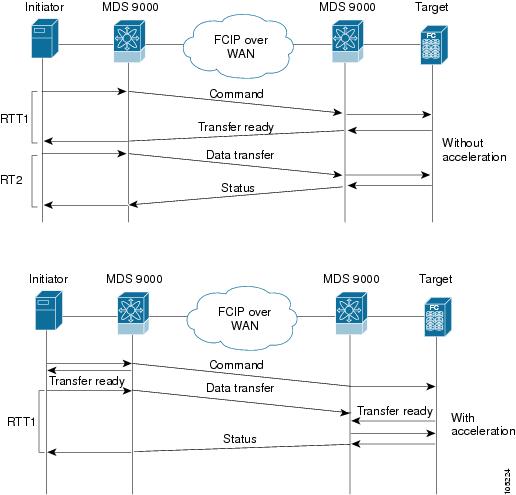
In Figure 2-9, the SCSI WRITE command without Write Acceleration requires two round-trip transfers (RTT), while the SCSI WRITE command with Write Acceleration only requires one RTT. The maximum sized Transfer Ready is sent from the host side of the FCIP link back to the host before the SCSI WRITE command reaches the target. This enables the host to start sending the write data without waiting for the long latency over the FCIP link of the SCSI WRITE command and Transfer Ready. It also eliminates the delay caused by multiple Transfer Readys needed for the exchange going over the FCIP link.
Figure 2-9 FCIP Link Write Acceleration
Tip![]() FCIP Write Acceleration (WA) can be enabled for multiple FCIP links if the links are part of a port channel configured with "channel mode active". These are port channels constructed with Port Channel Protocol (PCP). Write Acceleration cannot be used across FSPF equal cost paths in FCIP deployments. Native Fibre Channel Write Acceleration can be used with port channels. Also, FCIP Write Acceleration can be used in port channels configured with channel mode active or constructed with Port Channel Protocol (PCP). FCIP WA does not work if multiple non-port channel FCIP links exist with equal cost between the initiator and the target ports. This configuration might cause either SCSI discovery failure or failed WRITE or READ operations. When FCIP WA is used the FSPF routing should ensure that a single FCIP Port-Channel or ISL is always in the path between the initiator and the target ports.
FCIP Write Acceleration (WA) can be enabled for multiple FCIP links if the links are part of a port channel configured with "channel mode active". These are port channels constructed with Port Channel Protocol (PCP). Write Acceleration cannot be used across FSPF equal cost paths in FCIP deployments. Native Fibre Channel Write Acceleration can be used with port channels. Also, FCIP Write Acceleration can be used in port channels configured with channel mode active or constructed with Port Channel Protocol (PCP). FCIP WA does not work if multiple non-port channel FCIP links exist with equal cost between the initiator and the target ports. This configuration might cause either SCSI discovery failure or failed WRITE or READ operations. When FCIP WA is used the FSPF routing should ensure that a single FCIP Port-Channel or ISL is always in the path between the initiator and the target ports.
Only one FCIP port channel is supported per VSAN on FCIPs configured on Cisco MDS 9700 Series switches with Write Acceleration configured.
Tip![]() Do not enable time stamp control on an FCIP interface with Write Acceleration configured.
Do not enable time stamp control on an FCIP interface with Write Acceleration configured.
Note![]() From Cisco MDS NX-OS Release 7.3(1)DY(1) and later, FCIP Write Acceleration can be enabled when FCIP port channels are configured between a Cisco MDS 9250i switch and a Cisco MDS 24/10 port SAN Extension Module in a Cisco MDS 9700 Director.
From Cisco MDS NX-OS Release 7.3(1)DY(1) and later, FCIP Write Acceleration can be enabled when FCIP port channels are configured between a Cisco MDS 9250i switch and a Cisco MDS 24/10 port SAN Extension Module in a Cisco MDS 9700 Director.
Ensure that the following prerequisites are met before enabling Write Acceleration:
- Use the fcip-enhanced command on the Cisco MDS 9220i and MDS 9250i switches while creating new port channels for FCIP ports. For more information on creating port channels, see the Configuring Port Channels chapter in the Cisco MDS 9000 Series Interfaces Configuration Guide. For more information on the fcip-enhanced command, see the Cisco MDS 9000 Series Command Reference.
- When you configure FCIP port channels between Cisco MDS 9250i and MDS 9700 switches and if write acceleration is enabled on the FCIP ports, then ensure that you enable write acceleration on the FCIP port-channels using the fcip-enhanced command on the Cisco MDS 9250i switch. For more information on creating port channels, see the Configuring Port Channels chapter in the Cisco MDS 9000 Series Interfaces Configuration Guide. For more information on the fcip-enhanced command, see the Cisco MDS 9000 Series Command Reference.
- Use the show port-channel database command to ensure that only FCIP interfaces are members of port channels.
- Enable passive-mode on FCIP interfaces created on a Cisco MDS 24/10 port SAN Extension Module in a Cisco MDS 9700 Director. For more information on enabling passive mode, see the Configuring Active Connections section.
Note In Cisco MDS NX-OS Release 8.1(1) and later, Write Acceleration on FCIP port channels should not be configured between two MDS 9700 Series switches with Cisco MDS 24/10 port SAN Extension Module under the following conditions:
- If traffic flows between an FCoE port and an FC port through an FCIP port channel.
- If traffic flows through two successive FCIP port channels, one after another.
Configuring FCIP Write Acceleration
To enable Write Acceleration, follow these steps:
|
|
|
|
|---|---|---|
Displaying Write Acceleration Activity Information
Example 2-10 through Example 2-12 show how to display information about Write Acceleration activity.
Example 2-10 Displaying the Exchanges Processed by Write Acceleration at the Specified Host-End FCIP Link
Example 2-11 Displaying Exchanges Processed by Write Acceleration at the Specified Target End FCIP Link
Example 2-12 Displaying Detailed FCIP Interface Write Acceleration Counter Information
FCIP Tape Acceleration
The FCIP Tape Acceleration feature enables you to significantly improve application write performance when storage traffic is routed over wide area networks using FCIP. When FCIP Tape Acceleration is enabled, WAN throughput is maximized by acknowledging the frames from the sender at the closer FCIP switch, thereby eliminating the impact of WAN latency for write operations. The FCIP TAPE Acceleration feature is disabled by default and must be enabled on both sides of the FCIP link.
Tapes are storage devices that store and retrieve user data sequentially. Cisco MDS NX-OS provides both tape write and read acceleration.
Applications that access tape drives normally have only one SCSI WRITE or READ operation outstanding to it. This single command process limits the benefit of the tape acceleration feature when using an FCIP link over a long-distance WAN link. It impacts backup and performance because each SCSI WRITE or READ operation does not complete until the host receives a good status response from the tape drive. The FCIP tape acceleration feature helps solve this problem. It improves tape backup, archive, and restore operations by allowing faster data streaming between the host and tape drive over the WAN link.
In an example of tape acceleration for write operations, the backup server in Figure 2-10 issues write operations to a drive in the tape library. Acting as a proxy for the remote tape drives, the local Cisco MDS switch proxies a transfer ready to signal the host to start sending data. After receiving all the data, the local Cisco MDS switch proxies the successful completion of the SCSI WRITE operation. This response allows the host to start the next SCSI WRITE operation. This proxy method results in more data being sent over the FCIP link in the same time period compared to the time taken to send data without proxying. The proxy method improves the performance on WAN links.
Figure 2-10 FCIP Link Tape Acceleration for Write Operations
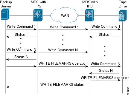
At the tape end of the FCIP link, another Cisco MDS switch buffers the command and data it has received. It then acts as a backup server to the tape drive by listening to a transfer ready from the tape drive before forwarding the data.
Note![]() In some cases such as a quick link up/down event (FCIP link, Server/Tape Port link) in a tape library environment that exports Control LUN or a Medium Changer as LUN 0 and tape drives as other LUNs, tape acceleration may not detect the tape sessions and may not accelerate these sessions. You need to keep the FCIP link disabled for a couple of minutes before enabling the link. This does not apply to tape environments where the tape drives are either direct FC attached or exported as LUN 0.
In some cases such as a quick link up/down event (FCIP link, Server/Tape Port link) in a tape library environment that exports Control LUN or a Medium Changer as LUN 0 and tape drives as other LUNs, tape acceleration may not detect the tape sessions and may not accelerate these sessions. You need to keep the FCIP link disabled for a couple of minutes before enabling the link. This does not apply to tape environments where the tape drives are either direct FC attached or exported as LUN 0.
The Cisco NX-OS provides reliable data delivery to the remote tape drives using TCP/IP over the WAN. It maintains write data integrity by allowing the WRITE FILEMARKS operation to complete end-to-end without proxying. The WRITE FILEMARKS operation signals the synchronization of the buffer data with the tape library data. While tape media errors are returned to backup servers for error handling, tape busy errors are retried automatically by the Cisco NX-OS software.
In an example of tape acceleration for read operations, the restore server in Figure 2-11 issues read operations to a drive in the tape library. During the restore process, the remote Cisco MDS switch at the tape end, in anticipation of more SCSI read operations from the host, sends out SCSI read operations on its own to the tape drive. The prefetched read data is cached at the local Cisco MDS switch. The local Cisco MDS switch on receiving SCSI read operations from the host, sends out the cached data. This method results in more data being sent over the FCIP link in the same time period compared to the time taken to send data without read acceleration for tapes. This improves the performance for tape reads on WAN links.
Figure 2-11 FCIP Link Tape Acceleration for Read Operations

The Cisco NX-OS provides reliable data delivery to the restore application using TCP/IP over the WAN. While tape media errors during the read operation are returned to the restore server for error handling, the Cisco NX-OS software recovers from any other errors.
Note![]() The FCIP tape acceleration feature is disabled by default and must be enabled on both sides of the FCIP link. If it is only enabled on one side of the FCIP link, the tape acceleration feature is operationally off.
The FCIP tape acceleration feature is disabled by default and must be enabled on both sides of the FCIP link. If it is only enabled on one side of the FCIP link, the tape acceleration feature is operationally off.
Tip![]() FCIP tape acceleration does not work if the FCIP port is part of a port channel or if there are multiple paths between the initiator and the target port. Such a configuration might cause either SCSI discovery failure or broken write or read operations.
FCIP tape acceleration does not work if the FCIP port is part of a port channel or if there are multiple paths between the initiator and the target port. Such a configuration might cause either SCSI discovery failure or broken write or read operations.
When tape acceleration is enabled in an FCIP interface, a FICON VSAN cannot be enabled in that interface. Likewise, if an FCIP interface is up in a FICON VSAN, tape acceleration cannot be enabled on that interface.
Note![]() When you enable the tape acceleration feature for an FCIP link, the link is reinitialized and the write and read acceleration feature is also automatically enabled.
When you enable the tape acceleration feature for an FCIP link, the link is reinitialized and the write and read acceleration feature is also automatically enabled.
In tape acceleration for writes, after a certain amount of data has been buffered at the remote Cisco MDS switch, the write operations from the host are flow controlled by the local Cisco MDS switch by not proxying the Transfer Ready. On completion of a write operation when some data buffers are freed, the local Cisco MDS switch resumes the proxying. Likewise, in tape acceleration for reads, after a certain amount of data has been buffered at the local Cisco MDS switch, the read operations to the tape drive are flow controlled by the remote Cisco MDS switch by not issuing any further reads. On completion of a read operation, when some data buffers are freed, the remote Cisco MDS switch resumes issuing reads.
The default flow control buffering uses the automatic option. This option takes the WAN latencies and the speed of the tape into account to provide optimum performance. You can also specify a flow control buffer size (the maximum buffer size is 12 MB).
We recommend that you use the default option for flow-control buffering.
Note![]() Starting from Cisco MDS NX-OS Release 7.3(0)DY(1), FCIP tape acceleration will work with five TCP connections.
Starting from Cisco MDS NX-OS Release 7.3(0)DY(1), FCIP tape acceleration will work with five TCP connections.
Tip![]() Do not enable time-stamp control on an FCIP interface with tape acceleration configured.
Do not enable time-stamp control on an FCIP interface with tape acceleration configured.
Tape Library LUN Mapping for FCIP Tape Acceleration
If a tape library provides logical unit (LU) mapping and FCIP tape acceleration is enabled, you must assign a unique LU number (LUN) to each physical tape drive accessible through a target port.
Figure 2-12 shows tape drives connected to Switch 2 through a single target port. If the tape library provides LUN mapping, then all the four tape drives should be assign unique LUNs.
Figure 2-12 FCIP LUN Mapping Example
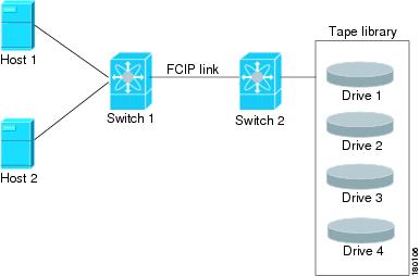
For the mappings described in Table 2-2 and Table 2-3 , Host 1 has access to Drive 1 and Drive 2, and Host 2 has access to Drive 3 and Drive 4.
Table 2-2 describes correct tape library LUN mapping.
|
|
|
|
|---|---|---|
Table 2-3 describes incorrect tape library LUN mapping.
|
|
|
|
|---|---|---|
Another example setup is when a tape drive is shared by multiple hosts through a single tape port. For instance, Host 1 has access to Drive1 and Drive2, and Host 2 has access to Drive 2, Drive 3, and Drive 4. A correct LUN mapping configuration for such a setup is shown in Table 2-4 .
|
|
|
|
|---|---|---|
Configuring FCIP Tape Acceleration
Note![]() In an FCIP tape acceleration link, if the trunk mode is on for TA enabled links, then the trunk mode allowed VSAN should be configured such that each VSAN’s traffic passes through only one link. If the traffic passes through multiple links, it may cause traffic failures.
In an FCIP tape acceleration link, if the trunk mode is on for TA enabled links, then the trunk mode allowed VSAN should be configured such that each VSAN’s traffic passes through only one link. If the traffic passes through multiple links, it may cause traffic failures.
To enable FCIP tape acceleration, follow these steps:
Displaying Tape Acceleration Activity Information
Example 2-13 through Example 2-16 show how to display information about tape acceleration activity.
Example 2-13 Displaying Information About Tapes for Which Exchanges are Tape Accelerated
Example 2-14 Displaying Information About Tapes for Which Exchanges are Tape Accelerated at the Host-End FCIP Link
Example 2-15 Displaying Information About Tapes for Which Exchanges are Tape Accelerated at the Target-End FCIP Link
Example 2-16 Displays Detailed FCIP Interface Tape Acceleration Counter Information, if Enabled
FCIP Compression
The FCIP compression option allows IP packets to be compressed on an FCIP link. This option is enabled per FCIP link. The FCIP maximum bandwidth configuration is calculated on the size of the FC frames. Since compression is done at the IP layer and FC is above the IP layer, enabling compression will not cause FCIP interfaces to transmit more than without it (that is, not increase FC throughput). Rather, it helps in reducing the amount of IP traffic sent over the IP network (that is, reduces the IP load). By default, FCIP compression is disabled. When enabled without specifying a compression mode, a compression algorithm appropriate for the FCIP service engine and link speed (as configured in the TCP parameters of the FCIP profile) is automatically used.
Note![]() The main purpose of the FCIP compression feature is to increase throughput on low bandwidth IP connections which are hitting maximum bandwidth usage. Depending on the IP Services switch or module used, the performance of the built-in IP compression engine can be significantly lower than the maximum line rate of IPStorage ports. Therefore, configuring FCIP compression on high bandwidth links can be detrimental to the overall application level performance.
The main purpose of the FCIP compression feature is to increase throughput on low bandwidth IP connections which are hitting maximum bandwidth usage. Depending on the IP Services switch or module used, the performance of the built-in IP compression engine can be significantly lower than the maximum line rate of IPStorage ports. Therefore, configuring FCIP compression on high bandwidth links can be detrimental to the overall application level performance.
The Cisco MDS 9250i switch and Cisco 24/10 port SAN Extension Module supports Auto, Mode1 and Mode2 compression modes. All of these modes internally use the hardware compression engine in the module. Auto mode is enabled by default. Mode2 uses a larger batch size for compression than Auto-mode, which results in higher compression throughput. However, Mode2 incurs a small latency due to the compression throughput. For those deployments where aggressive throughput is most important, Mode2 can be used. Mode1 gives the best compression ratio when compared to all other modes. For those deployments where compression ratio is most important, Mode1 can be used.
Note![]() If both ends of an FCIP link are running Cisco MDS NX-OS Release 8.1(1) or later, and you enable compression at one end of the FCIP link, be sure to enable it at the other end of the link also.
If both ends of an FCIP link are running Cisco MDS NX-OS Release 8.1(1) or later, and you enable compression at one end of the FCIP link, be sure to enable it at the other end of the link also.
Note![]() When using FCIP compression, the rates specified in tcp max-bandwidth-xxxx and min-available-bandwidth-xxxx in the FCIP profile are in compressed bites.
When using FCIP compression, the rates specified in tcp max-bandwidth-xxxx and min-available-bandwidth-xxxx in the FCIP profile are in compressed bites.
Configuring FCIP Compression
To enable FCIP compression, follow these steps:
|
|
|
|
|---|---|---|
Displaying FCIP Compression Information
Example 2-17 and Example 2-19 show how to display FCIP compression information.
Example 2-17 Displaying Detailed FCIP Interface Compression Information, if Enabled
Example 2-18 Displaying the Compression Engine Statistics for the 9250i
Example 2-19 Displaying the Compression Engine Statistics for 24/10 port SAN Extension Module
Configuring FCIP Links for Maximum Performance
This section describes how to configure FCIP links for optimum performance between two Cisco MDS 9250i switches, or two 24/10 port SAN Extension Modules. We recommend that the maximum and minimum bandwidth parameters in an FCIP profile be the same on both the sides.
Note ●![]() FCIP links with a tcp max-bandwidth-mbps of 33 Mbps or less will result in FSPF cost of 30000. This makes the interface unusable. Starting from Cisco MDS NX-OS Releases 8.2(1), the FSPF cost for low bandwidth FCIP links is set to 28999. Because this value is less than the FSPF maximum cost of 30000, and it will allow the traffic to be routed across the interface. It also allows additional FC or FCoE hops (including the FCIP hop) in the end-to-end path. The total FSPF cost of these additional hops should not exceed 1000, because the path will not be usable. If the FSPF cost of 28999 is not applicable for a specific topology, it should be manually configured using the fspf cost interface configuration command. To check the FSPF cost of an interface, use the show fspf interface command.
FCIP links with a tcp max-bandwidth-mbps of 33 Mbps or less will result in FSPF cost of 30000. This makes the interface unusable. Starting from Cisco MDS NX-OS Releases 8.2(1), the FSPF cost for low bandwidth FCIP links is set to 28999. Because this value is less than the FSPF maximum cost of 30000, and it will allow the traffic to be routed across the interface. It also allows additional FC or FCoE hops (including the FCIP hop) in the end-to-end path. The total FSPF cost of these additional hops should not exceed 1000, because the path will not be usable. If the FSPF cost of 28999 is not applicable for a specific topology, it should be manually configured using the fspf cost interface configuration command. To check the FSPF cost of an interface, use the show fspf interface command.
For more information on FSPF Cost, see the Cisco MDS Fabric Configuration Guide.
- FSPF equal cost multipath (ECMP) cannot be used to load balance the traffic across different types of ISLs. In other words, two or more equal cost ISLs of a different type between two switches (e.g. FCIP + FC, or FCIP + FCoE) is not supported.
- On Cisco MDS 24/10 Port SAN Extension Module, configuring multiple ECMP port channels with FCIP members in the same VSAN is not a valid configuration. If this is configured, then traffic will flow through only one of the port channels.
Configuring FCIP Links for Maximum Performance on a Cisco MDS 9250i Switch
To achieve maximum FCIP performance in 10 Gbps mode, the following configuration is recommended:
Step 1![]() Create an FCIP link on the IPStorage port.
Create an FCIP link on the IPStorage port.
If more than two FCIP links are bound to an IPStorage interface at 10 Gbps, the combined maximum bandwidth of all links bound to that interface must not exceed 10 Gbps.
Step 2![]() Set the TCP maximum and minimum bandwidth to 5000 Mbps and 4000 Mbps respectively (default value).
Set the TCP maximum and minimum bandwidth to 5000 Mbps and 4000 Mbps respectively (default value).
Step 3![]() Configure five TCP connections on each FCIP link.
Configure five TCP connections on each FCIP link.
Step 4![]() Set the MTU size to 2500 on the IPStorage port.
Set the MTU size to 2500 on the IPStorage port.
To achieve maximum FCIP performance in 10 Gbps mode, follow these configuration steps:
To achieve maximum FCIP performance in 1 Gbps mode, the following configuration is recommended:
Step 1![]() Create an FCIP link on the IPStorage port.
Create an FCIP link on the IPStorage port.
Note![]() If more than one FCIP link is bound to an IPStorage interface at 1 Gbps, the combined maximum bandwidth of all links bound to that interface must not exceed 1 Gbps.
If more than one FCIP link is bound to an IPStorage interface at 1 Gbps, the combined maximum bandwidth of all links bound to that interface must not exceed 1 Gbps.
Step 2![]() Set the TCP maximum and minimum bandwidth as 1000 Mbps and 800 Mbps respectively.
Set the TCP maximum and minimum bandwidth as 1000 Mbps and 800 Mbps respectively.
Note![]() If the TCP maximum bandwidth is set to any value more than 1000 Mbps, we recommend that you set the number of TCP connections to five.
If the TCP maximum bandwidth is set to any value more than 1000 Mbps, we recommend that you set the number of TCP connections to five.
Step 3![]() Configure two TCP connections on each FCIP link.
Configure two TCP connections on each FCIP link.
Step 4![]() Set the MTU size to 2500 for the IPStorage port.
Set the MTU size to 2500 for the IPStorage port.
Step 5![]() Enable compression on each FCIP link.
Enable compression on each FCIP link.
To achieve maximum FCIP performance in 1 Gbps mode, follow these configuration steps:
Configuring FCIP Links for Maximum Performance on Cisco MDS 24/10 port SAN Extension Module
To achieve maximum FCIP performance in 10 Gbps mode, the following configuration is recommended:
Step 1![]() Create an FCIP link on the IPStorage port.
Create an FCIP link on the IPStorage port.
If more than two FCIP links are bound to an IPStorage interface at 10 Gbps, the combined maximum bandwidth of all links bound to that interface must not exceed 10 Gbps.
Step 2![]() Set the TCP maximum and minimum bandwidth to 10000 Mbps and 8000 Mbps respectively (default value).
Set the TCP maximum and minimum bandwidth to 10000 Mbps and 8000 Mbps respectively (default value).
Step 3![]() Configure five TCP connections on each FCIP link.
Configure five TCP connections on each FCIP link.
Step 4![]() Set the MTU size to 2500 on the IPStorage port.
Set the MTU size to 2500 on the IPStorage port.
To achieve maximum FCIP performance in 10 Gbps mode, follow these configuration steps:
To achieve maximum FCIP performance in 1 Gbps mode, the following configuration is recommended:
Step 1![]() Create an FCIP link on the IPStorage port.
Create an FCIP link on the IPStorage port.
Note![]() If more than one FCIP link is bound to an IPStorage interface at 1 Gbps, the combined maximum bandwidth of all links bound to that interface must not exceed 1 Gbps.
If more than one FCIP link is bound to an IPStorage interface at 1 Gbps, the combined maximum bandwidth of all links bound to that interface must not exceed 1 Gbps.
Step 2![]() Set the TCP maximum and minimum bandwidth as 1000 Mbps and 800 Mbps respectively.
Set the TCP maximum and minimum bandwidth as 1000 Mbps and 800 Mbps respectively.
Note![]() If the TCP maximum bandwidth is set to a value that is more than 1000 Mbps, we recommend that you set the number of TCP connections to five.
If the TCP maximum bandwidth is set to a value that is more than 1000 Mbps, we recommend that you set the number of TCP connections to five.
Step 3![]() Configure two TCP connections on each FCIP link.
Configure two TCP connections on each FCIP link.
Step 4![]() Set the MTU size to 2500 for the IPStorage port.
Set the MTU size to 2500 for the IPStorage port.
To achieve maximum FCIP performance in 1 Gbps mode, follow these configuration steps:
Verifying FCIP Configuration
To verify FCIP configurations, use the following commands:
Default Settings for FCIP Parameters
Table 2-5 lists the default settings for FCIP parameters.
 Feedback