- Cisco MDS 9000 Series IP Services Configuration Guide, Release 8.x
- New and Changed Information
- Preface
- Overview
- Configuring FCIP
- Configuring the SAN Extension Tuner
- Configuring iSCSI
- Configuring IP Services
- Configuring IP Storage Services
- Configuring IPv4 for Gigabit Ethernet Interfaces
- Configuring IPv6
- Index
- Overview of iSCSI
- Configuring iSCSI
- Enabling iSCSI
- Creating iSCSI Interfaces
- Using the iSCSI Wizard
- Presenting Fibre Channel Targets as iSCSI Targets
- Presenting iSCSI Hosts as Virtual Fibre Channel Hosts
- Initiator Presentation Modes
- iSCSI Initiator Idle Timeout
- VSAN Membership for iSCSI
- Configuring VSAN Membership for iSCSI Hosts
- Configuring Default Port VSAN for iSCSI Interfaces
- iSCSI Access Control
- Fibre Channel Zoning-Based Access Control
- iSCSI-Based Access Control
- Enforcing Access Control
- iSCSI Session Authentication
- iSCSI Immediate Data and Unsolicited Data Features
- iSCSI Interface Advanced Features
- Displaying iSCSI Information
- Configuring iSLB
- iSLB Configuration Limits
- iSLB Configuration Prerequisites
- iSLB Initiators
- Configuring iSLB Using Device Manager
- Configuring iSLB Initiators
- Configuring Metrics for Load Balancing
- Verifying iSLB Initiator Configuration
- Configuring iSLB Initiator Targets
- Configuring and Activating Zones for iSLB Initiators and Initiator Targets
- Verifying iSLB Zoning Configuration
- Configuring iSLB Session Authentication
- Load Balancing Using VRRP
- Configuring Load Balancing Using VRRP
- Verifying iSLB VRRP Load Balancing Configuration
- Displaying iSLB VRRP Information
- iSLB Configuration Distribution Using CFS
- Distributing iSLB Configuration Using CFS
- iSCSI High Availability
- iSCSI Authentication Setup Guidelines and Scenarios
- Configuring No Authentication
- Configuring CHAP with Local Password Database
- Configuring CHAP with External RADIUS Server
- iSCSI Transparent Mode Initiator
- Target Storage Device Requiring LUN Mapping
- Overview of Internet Storage Name Service
- Overview of iSNS Client Functionality
- Creating an iSNS Client Profile
- Verifying iSNS Client Configuration
- iSNS Server Functionality
- Configuring an iSNS Server
- iSNS Cloud Discovery
- Default Settings
Configuring Internet Small Computer Systems Interface
Cisco MDS 9000 Family IP storage (IPS) services extend the reach of Fibre Channel SANs by using open-standard, IP-based technology. The switch allows IP hosts to access Fibre Channel storage using the Internet Small Computer Systems Interface (iSCSI) protocol.

Note![]() The iSCSI feature is specific to the Fibre Channel module with IPS ports and is available in Cisco MDS 9200 Switches or Cisco MDS 9500 Directors. In Cisco MDS NX-OS Release 7.3(0)DY(1) and later, iSCSI is not supported on Cisco MDS 9700 Directors with 24/10 port SAN Extension modules.
The iSCSI feature is specific to the Fibre Channel module with IPS ports and is available in Cisco MDS 9200 Switches or Cisco MDS 9500 Directors. In Cisco MDS NX-OS Release 7.3(0)DY(1) and later, iSCSI is not supported on Cisco MDS 9700 Directors with 24/10 port SAN Extension modules.
The Cisco MDS 9216i switch and the 14/2 Multiprotocol Services (MPS-14/2) module also allow you to use Fibre Channel, FCIP, and iSCSI features. The MPS-14/2 module is available for use in any switch in the Cisco MDS 9200 Series or Cisco MDS 9500 Series.
Note![]() For information on configuring Gigabit Ethernet interfaces, see “Basic Gigabit Ethernet Configuration for IPv4” section.
For information on configuring Gigabit Ethernet interfaces, see “Basic Gigabit Ethernet Configuration for IPv4” section.
This chapter includes the following sections:
- Overview of iSCSI
- Configuring iSCSI
- Configuring iSLB
- iSCSI High Availability
- iSCSI Authentication Setup Guidelines and Scenarios
- iSNS Cloud Discovery
- Default Settings
Overview of iSCSI
Cisco MDS 9000 Family IP Storage (IPS) services extend the reach of Fibre Channel SANs by using open-standard, IP-based technology. The iSCSI feature consists of routing iSCSI requests and responses between iSCSI hosts in an IP network and Fibre Channel storage devices in the Fibre Channel SAN that are accessible from any Fibre Channel interface of the Cisco MDS 9000 Family switch. Using the iSCSI protocol, the iSCSI driver allows an iSCSI host to transport SCSI requests and responses over an IP network. To use the iSCSI feature, you must explicitly enable iSCSI on the required switches in the fabric.
Note![]() The iSCSI feature is not supported on the Cisco Fabric Switch for HP c-Class Bladesystem and Cisco Fabric Switch for IBM BladeCenter.
The iSCSI feature is not supported on the Cisco Fabric Switch for HP c-Class Bladesystem and Cisco Fabric Switch for IBM BladeCenter.
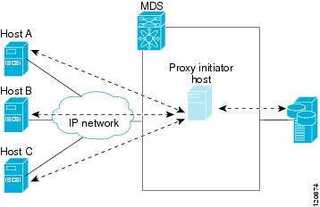
The iSCSI feature consists of routing iSCSI requests and responses between iSCSI hosts in an IP network and Fibre Channel storage devices in the Fibre Channel SAN that are accessible from any Fibre Channel interface of the Cisco MDS 9000 Family switch (see Figure 4-1).
Figure 4-1 Transporting iSCSI Requests and Responses for Transparent iSCSI Routing
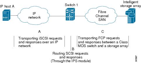
Each iSCSI host that requires access to storage through the Fibre Channel module with IPS ports or MPS-14/2 module needs to have a compatible iSCSI driver installed. Using the iSCSI protocol, the iSCSI driver allows an iSCSI host to transport SCSI requests and responses over an IP network. From the host operating system perspective, the iSCSI driver appears to be an SCSI transport driver similar to a Fibre Channel driver in the host.
The Fibre Channel module with IPS ports or MPS-14/2 module provides transparent SCSI routing. IP hosts using the iSCSI protocol can transparently access targets on the Fibre Channel network. It (see Figure 4-1) provides an example of a typical configuration of iSCSI hosts connected to an Fibre Channel module with IPS ports or MPS-14/2 module through the IP network access Fibre Channel storage on the Fibre Channel SAN.
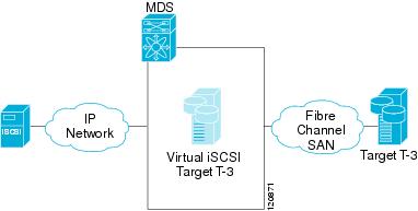
The Fibre Channel module with IPS ports or MPS-14/2 module create a separate iSCSI SAN view and Fibre Channel SAN view. For the iSCSI SAN view, the Fibre Channel module with IPS ports or MPS-14/2 module creates iSCSI virtual targets and then maps them to physical Fibre Channel targets available in the Fibre Channel SAN. They present the Fibre Channel targets to IP hosts as if the physical iSCSI targets were attached to the IP network (see Figure 4-2).
Figure 4-2 iSCSI SAN View—iSCSI Virtual Targets
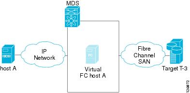
For the Fibre Channel SAN view, the Fibre Channel module with IPS ports or MPS-14/2 module presents iSCSI hosts as a virtual Fibre Channel host. The storage devices communicate with the virtual Fibre Channel host similar to communications performed with real Fibre Channel hosts (see Figure 4-3).
Figure 4-3 Fibre Channel SAN View—iSCSHI Host as an HBA
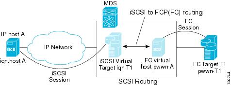
The Fibre Channel module with IPS ports or MPS-14/2 modules transparently map the command between the iSCSI virtual target and the virtual Fibre Channel host (see Figure 4-4).
Figure 4-4 iSCSI to FCP (Fibre Channel) Routing
Routing SCSI from the IP host to the Fibre Channel storage device consists of the following main actions:
- The iSCSI requests and responses are transported over an IP network between the hosts and the Fibre Channel module with IPS ports or MPS-14/2 module.
- The SCSI requests and responses are routed between the hosts on an IP network and the Fibre Channel storage device (converting iSCSI to FCP and vice versa). The Fibre Channel module with IPS ports or MPS-14/2 module performs this conversion and routing.
- The FCP requests or responses are transported between the Fibre Channel module with IPS ports or MPS-14/2 module and the Fibre Channel storage devices.
Note![]() FCP (the Fibre Channel equivalent of iSCSI) carries SCSI commands over a Fibre Channel SAN.
FCP (the Fibre Channel equivalent of iSCSI) carries SCSI commands over a Fibre Channel SAN.
Refer to the IETF standards for IP storage at http://www.ietf.org for information on the iSCSI protocol.
iSCSI Configuration Limits
iSCSI configuration has the following limits:
- The maximum number of iSCSI and iSLB initiators supported in a fabric is 2000.
- The maximum number of iSCSI and iSLB initiators supported is 200 per port.
- The maximum number of iSCSI and iSLB sessions supported by an IPS port in either transparent or proxy initiator mode is 500.
- The maximum number of iSCSI and iSLB session support by switch is 5000.
- The maximum number of iSCSI and iSLB targets supported in a fabric is 6000.
Configuring iSCSI
This section describes how to configure iSCSI on the Cisco MDS 9000 Family switches.
This section includes the following sections:
- Enabling iSCSI
- Creating iSCSI Interfaces
- Using the iSCSI Wizard
- Presenting Fibre Channel Targets as iSCSI Targets
- Presenting iSCSI Hosts as Virtual Fibre Channel Hosts
- iSCSI Access Control
- iSCSI Session Authentication
- iSCSI Immediate Data and Unsolicited Data Features
- iSCSI Interface Advanced Features
Enabling iSCSI
To use the iSCSI feature, you must explicitly enable iSCSI on the required switches in the fabric. Alternatively, you can enable or disable the iSCSI feature directly on the required modules using Fabric Manager or Device Manager. By default, this feature is disabled in all switches in the Cisco MDS 9000 Family.
To enable iSCSI on any participating switch, follow these steps:
|
|
|
|
|---|---|---|
Enters the configuration commands, one per line. End with CNTL/Z. |
||
Enables iSCSI modules on the switch. Note New command added so that SME and iSCSI are available on the same switch. |
||

To enable iSCSI on any switch using Fabric Manager, follow these steps:
Step 1![]() Choose End Devices > iSCSI in the Physical Attributes pane.
Choose End Devices > iSCSI in the Physical Attributes pane.
You see the iSCSI tables in the Information pane (see Figure 4-5).
Figure 4-5 iSCSI Tables in Fabric Manager
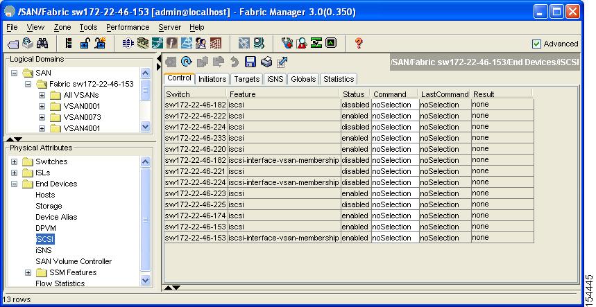
The Control tab is the default tab. You see the iSCSI enable status for all switches in the fabric that contain IPS ports.
Step 2![]() Choose enable from the Command column for each switch that you want to enable iSCSI on.
Choose enable from the Command column for each switch that you want to enable iSCSI on.
Step 3![]() Click the Apply Changes icon to save these changes.
Click the Apply Changes icon to save these changes.
To enable iSCSI on a module using Fabric Manager, follow these steps:
Step 1![]() Choose End Devices > iSCSI in the Physical Attributes pane.
Choose End Devices > iSCSI in the Physical Attributes pane.
You see the iSCSI tables in the Information pane.
Step 2![]() Click the Module Control tab.
Click the Module Control tab.
You see the Module Control dialog box in the information pane (see Figure 4-6).
Figure 4-6 Module Control Dialog Box
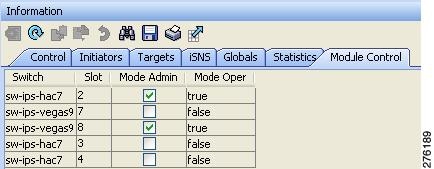
Step 3![]() Check the Mode Admin check box to enable iSCSI for a specified port on the selected module.
Check the Mode Admin check box to enable iSCSI for a specified port on the selected module.
Step 4![]() Click the Apply Changes icon to save these changes.
Click the Apply Changes icon to save these changes.
To enable iSCSI on a module using Device Manager, follow these steps:
You see the iSCSI table (see Figure 4-7).
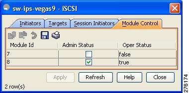
Step 2![]() Check the Mode Admin check box to enable iSCSI for the specified port on the selected module.
Check the Mode Admin check box to enable iSCSI for the specified port on the selected module.
Step 3![]() Click Apply to save these changes.
Click Apply to save these changes.
Creating iSCSI Interfaces
Each physical Gigabit Ethernet interface on an Fibre Channel module with IPS ports, MPS-14/2 module or 1/10Gbps IPStorage port on a Cisco MDS 9250i Multiservice Fabric Switch can be used to translate and route iSCSI requests to Fibre Channel targets and responses in the opposite direction. To enable this capability, the corresponding iSCSI interface must be in an enabled state.
To enable iSCSI interfaces, follow these steps:
Step 1![]() Enable the required Gigabit Ethernet interface.
Enable the required Gigabit Ethernet interface.
Step 2![]() Create the required iSCSI interface and enable the interface.
Create the required iSCSI interface and enable the interface.
Note![]() Use the tcp maximum-bandwidth-kbps and tcp maximum-bandwidth-mbps commands to configure the iSCSI speed and the switchport speed command to set the Physical IPStorage ports to 1Gbps or 10Gbps speed. The Cisco MDS switches do not limit the configuration of the iSCSI tcp maximum-bandwidth-kbps and maximum-bandwidth-mbps based on the speed of the underlying physical Gigabit Ethernet or IPStorage ports. Consequently, it is possible to configure iSCSI tcp maximum-bandwidth-kbps and tcp maximum-bandwidth-mbps commands to the equivalent of 10Gbps on a physical IPStorage port that is running at a 1Gbps speed. When configuring the tcp maximum bandwidth, ensure that it does not exceed the maximum speed of the physical IPStorage port.
Use the tcp maximum-bandwidth-kbps and tcp maximum-bandwidth-mbps commands to configure the iSCSI speed and the switchport speed command to set the Physical IPStorage ports to 1Gbps or 10Gbps speed. The Cisco MDS switches do not limit the configuration of the iSCSI tcp maximum-bandwidth-kbps and maximum-bandwidth-mbps based on the speed of the underlying physical Gigabit Ethernet or IPStorage ports. Consequently, it is possible to configure iSCSI tcp maximum-bandwidth-kbps and tcp maximum-bandwidth-mbps commands to the equivalent of 10Gbps on a physical IPStorage port that is running at a 1Gbps speed. When configuring the tcp maximum bandwidth, ensure that it does not exceed the maximum speed of the physical IPStorage port.
Using the iSCSI Wizard
To use the iSCSI wizard in Fabric Manager, follow these steps:
Step 1![]() Click the iSCSI Setup Wizard icon.
Click the iSCSI Setup Wizard icon.
You see the iSCSI Wizard Configure Initiator dialog box (see Figure 4-8).
Figure 4-8 iSCSI Wizard Configure Initiator Dialog Box
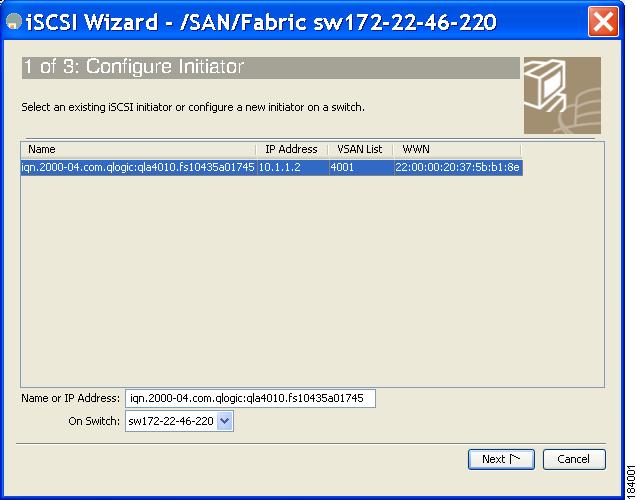
Step 2![]() Select an existing iSCSI initiator or add the iSCSI node name or IP address for a new iSCSI initiator.
Select an existing iSCSI initiator or add the iSCSI node name or IP address for a new iSCSI initiator.
Step 3![]() Select the switch for this iSCSI initiator if you are adding a new iSCSI initiator and click Next.
Select the switch for this iSCSI initiator if you are adding a new iSCSI initiator and click Next.
You see the iSCSI Wizard Select Targets dialog box (see Figure 4-9).
Figure 4-9 iSCSI Wizard Select Targets Dialog Box
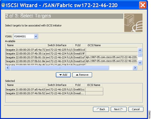
Step 4![]() Select the VSAN and targets to associate with this iSCSI initiator and click Next.
Select the VSAN and targets to associate with this iSCSI initiator and click Next.
Note![]() The iSCSI wizard turns on the Dynamic Import FC Targets feature.
The iSCSI wizard turns on the Dynamic Import FC Targets feature.
You see the iSCSI Wizard Select Zone dialog box (see Figure 4-10).
Figure 4-10 iSCSI Wizard Select Zone Dialog Box
Step 5![]() Set the zone name for this new iSCSI zone and check the ReadOnly check box if needed.
Set the zone name for this new iSCSI zone and check the ReadOnly check box if needed.
Step 6![]() Click Finish to create this iSCSI initiator.
Click Finish to create this iSCSI initiator.
If created, the target VSAN is added to the iSCSI host VSAN list.
Note![]() iSCSI wizard automatically turns on the Dynamic FC target import.
iSCSI wizard automatically turns on the Dynamic FC target import.
Presenting Fibre Channel Targets as iSCSI Targets
The Fibre Channel module with IPS ports or MPS-14/2 module presents physical Fibre Channel targets as iSCSI virtual targets, allowing them to be accessed by iSCSI hosts. The module presents these targets in one of the two ways:
- Dynamic mapping—Automatically maps all the Fibre Channel target devices/ports as iSCSI devices. Use this mapping to create automatic iSCSI target names.
- Static mapping—Manually creates iSCSI target devices and maps them to the whole Fibre Channel target port or a subset of Fibre Channel LUNs. With this mapping, you must specify unique iSCSI target names.
Static mapping should be used when iSCSI hosts should be restricted to subsets of LUs in the Fibre Channel targets and/or iSCSI access control is needed (see the “iSCSI Access Control” section). Also, static mapping allows the configuration of transparent failover if the LUs of the Fibre Channel targets are reachable by redundant Fibre Channel ports (see the “Transparent Target Failover” section).
Note![]() The Fibre Channel module with IPS ports or MPS-14/2 module does not import Fibre Channel targets to iSCSI by default. Either dynamic or static mapping must be configured before the Fibre Channel module with IPS ports or MPS-14/2 module makes Fibre Channel targets available to iSCSI initiators.
The Fibre Channel module with IPS ports or MPS-14/2 module does not import Fibre Channel targets to iSCSI by default. Either dynamic or static mapping must be configured before the Fibre Channel module with IPS ports or MPS-14/2 module makes Fibre Channel targets available to iSCSI initiators.
Dynamic Mapping
When you configure dynamic mapping the Fibre Channel module with IPS ports or MPS-14/2 module imports all Fibre Channel targets to the iSCSI domain and maps each physical Fibre Channel target port as one iSCSI target. That is, all LUs accessible through the physical storage target port are available as iSCSI LUs with the same LU number (LUN) as in the physical Fibre Channel target port.
The iSCSI target node name is created automatically using the iSCSI qualified name (IQN) format. The iSCSI qualified name is restricted to a maximum name length of 223 alphanumeric characters and a minimum length of 16 characters.
The Fibre Channel module with IPS ports or MPS-14/2 module creates an IQN formatted iSCSI target node name using the following conventions because the name must be unique in the SAN:
- IPS Gigabit Ethernet ports that are not part of a Virtual Router Redundancy Protocol (VRRP) group or port channel use this format:
Note![]() If you have configured a switch name, then the switch name is used instead of the management IP address. If you have not configured a switch name, the management IP address is used.
If you have configured a switch name, then the switch name is used instead of the management IP address. If you have not configured a switch name, the management IP address is used.
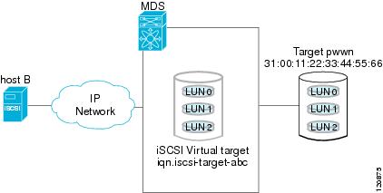
With this convention, each IPS port in a Cisco MDS 9000 Family switch creates a unique iSCSI target node name for the same Fibre Channel target port in the SAN.
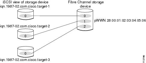
For example, if an iSCSI target was created for a Fibre Channel target port with pWWN 31:00:11:22:33:44:55:66 and that pWWN contains LUN 0, LUN 1, and LUN 2, those LUNs would become available to an IP host through the iSCSI target node name iqn.1987-05.com.cisco:05. MDS_switch_management_IP_address.01-01.3100112233445566 (see Figure 4-11).
Figure 4-11 Dynamic Target Mapping
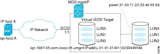
Note![]() Each iSCSI initiator may not have access to all targets depending on the configured access control mechanisms (see the “iSCSI Access Control” section).
Each iSCSI initiator may not have access to all targets depending on the configured access control mechanisms (see the “iSCSI Access Control” section).
To enable dynamic mapping of Fibre Channel targets into iSCSI, follow these steps:
|
|
|
|
|---|---|---|
Fibre Channel module with IPS ports and MPS-14/2 modules dynamically import all Fibre Channel targets in the Fibre Channel SAN into the IP network. |
To enable dynamic mapping of Fibre Channel targets into iSCSI using Device Manager, follow these steps:
You see the iSCSI configuration (see Figure 4-12).
Figure 4-12 iSCSI Configuration in Device Manager
Step 2![]() Click the Target tab to display a list of existing iSCSI targets (see Figure 4-13).
Click the Target tab to display a list of existing iSCSI targets (see Figure 4-13).
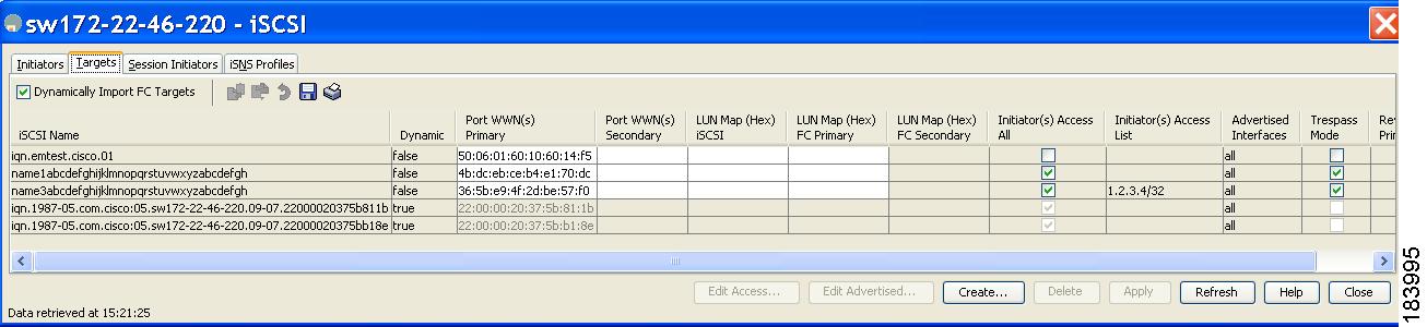
Step 3![]() Check the Dynamically Import FC Targets check box.
Check the Dynamically Import FC Targets check box.
Step 4![]() Click Apply to save this change.
Click Apply to save this change.
Static Mapping
You can manually (statically) create an iSCSI target by assigning a user-defined unique iSCSI node name to it. The iSCSI qualified name is restricted to a minimum length of 16 characters and a maximum of 223 characters. A statically mapped iSCSI target can either map the whole Fibre Channel target port (all LUNs in the target port mapped to the iSCSI target), or it can contain one or more LUs from a Fibre Channel target port (see Figure 4-14).
Figure 4-14 Statically Mapped iSCSI Targets
To create a static iSCSI virtual target for the entire Fibre Channel target port using Device Manager, follow these steps:
You see the iSCSI configuration (see Figure 4-12).
Step 2![]() Click the Targets tab to display a list of existing iSCSI targets (see Figure 4-13).
Click the Targets tab to display a list of existing iSCSI targets (see Figure 4-13).
Step 3![]() Click Create to create an iSCSI target.
Click Create to create an iSCSI target.
You see the Create iSCSI Targets dialog box (See Figure 4-15).
Figure 4-15 Create iSCSI Targets Dialog Box
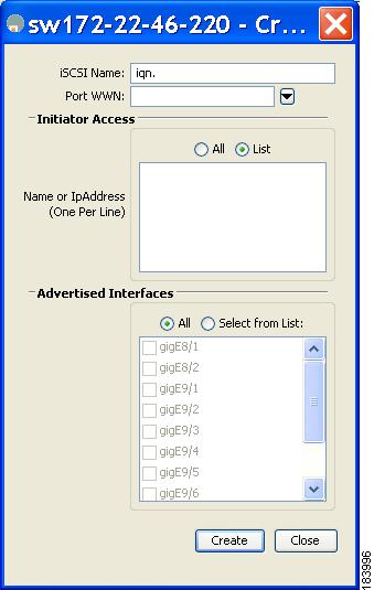
Step 4![]() Set the iSCSI target node name in the iSCSI Name field, in IQN format.
Set the iSCSI target node name in the iSCSI Name field, in IQN format.
Step 5![]() Set the Port WWN field for the Fibre Channel target port you are mapping.
Set the Port WWN field for the Fibre Channel target port you are mapping.
Step 6![]() Click the Select from List radio button and set the iSCSI initiator node names or IP addresses that you want this virtual iSCSI target to access, or click the All radio button to let the iSCSI target access all iSCSI initiators. Also see the “iSCSI Access Control” section.
Click the Select from List radio button and set the iSCSI initiator node names or IP addresses that you want this virtual iSCSI target to access, or click the All radio button to let the iSCSI target access all iSCSI initiators. Also see the “iSCSI Access Control” section.
Step 7![]() Click the Select from List radio button and check each interface you want to advertise the iSCSI targets on or click the All radio button to advertise all interfaces.
Click the Select from List radio button and check each interface you want to advertise the iSCSI targets on or click the All radio button to advertise all interfaces.
Step 8![]() Click Apply to save this change.
Click Apply to save this change.

Tip![]() An iSCSI target cannot contain more than one Fibre Channel target port. If you have already mapped the whole Fibre Channel target port, you cannot use the LUN mapping option.
An iSCSI target cannot contain more than one Fibre Channel target port. If you have already mapped the whole Fibre Channel target port, you cannot use the LUN mapping option.
Note![]() See the “iSCSI-Based Access Control” section for more information on controlling access to statically mapped targets.
See the “iSCSI-Based Access Control” section for more information on controlling access to statically mapped targets.
Advertising Static iSCSI Targets
You can limit the Gigabit Ethernet interfaces through which static iSCSI targets are advertised. By default iSCSI targets are advertised on all Gigabit Ethernet interfaces, subinterfaces, port channel interfaces, and port channel subinterfaces.
To configure a specific interface that should advertise the iSCSI virtual target using Device Manager, follow these steps:
You see the iSCSI configuration (see Figure 4-12).
Step 2![]() Click the Targets tab to display a list of existing iSCSI targets (see Figure 4-13).
Click the Targets tab to display a list of existing iSCSI targets (see Figure 4-13).
Step 3![]() Right-click the iSCSI target that you want to modify and click Edit Advertised.
Right-click the iSCSI target that you want to modify and click Edit Advertised.
You see the Advertised Interfaces dialog box.
Step 4![]() (Optional) Right-click an interface that you want to delete and click Delete.
(Optional) Right-click an interface that you want to delete and click Delete.
Step 5![]() (Optional) Click Create to advertise on more interfaces.
(Optional) Click Create to advertise on more interfaces.
You see the Create Advertised Interfaces dialog box.
To configure a specific interface that should advertise the iSCSI virtual target, follow these steps:
iSCSI Virtual Target Configuration Examples
This section provides three examples of iSCSI virtual target configurations.
Example 1
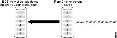
This example assigns the whole Fibre Channel target as an iSCSI virtual target. All LUNs that are part of the Fibre Channel target are available as part of the iSCSI target (see Figure 4-16).
Figure 4-16 Assigning iSCSI Node Names
Example 2
This example maps a subset of LUNs of a Fibre Channel target to three iSCSI virtual targets. Each iSCSI target only has one LUN (see Figure 4-17).
Figure 4-17 Mapping LUNs to an iSCSI Node Name
Example 3
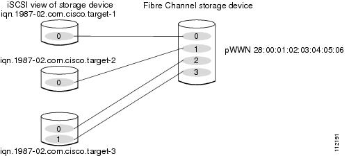
This example maps three subsets of Fibre Channel LUN targets to three iSCSI virtual targets. Two iSCSI targets have one LUN and the third iSCSI target has two LUNs (see Figure 4-18).
Figure 4-18 Mapping LUNs to Multiple iSCSI Node Names
Presenting iSCSI Hosts as Virtual Fibre Channel Hosts
The Fibre Channel module with IPS ports or MPS-14/2 module connects to the Fibre Channel storage devices on behalf of the iSCSI host to send commands and transfer data to and from the storage devices. These modules use a virtual Fibre Channel N port to access the Fibre Channel storage devices on behalf of the iSCSI host. iSCSI hosts are identified by either iSCSI qualified name (IQN) or IP address.
Initiator Identification
iSCSI hosts can be identified by the Fibre Channel module with IPS ports or MPS-14/2 module using the following:
An iSCSI initiator is identified based on the iSCSI node name it provides in the iSCSI login. This mode can be useful if an iSCSI host has multiple IP addresses and you want to provide the same service independent of the IP address used by the host. An initiator with multiple IP addresses (multiple network interface cards—NICs) has one virtual N port on each IPS port to which it logs in.
An iSCSI initiator is identified based on the IP address of the iSCSI host. This mode is useful if an iSCSI host has multiple IP addresses and you want to provide different service-based on the IP address used by the host. It is also easier to get the IP address of a host compared to getting the iSCSI node name. A virtual N port is created for each IP address it uses to log in to iSCSI targets. If the host using one IP address logs in to multiple IPS ports, each IPS port will create one virtual N port for that IP address.
You can configure the iSCSI initiator identification mode on each IPS port and all the iSCSI hosts terminating on the IPS port will be identified according to that configuration. The default mode is to identify the initiator by name.
To specify the initiator identification mode, follow these steps:
|
|
|
|
|---|---|---|
Selects the iSCSI interface on the switch that identifies all the initiators. |
||
Identifies the iSCSI initiator based on the initiator node name. This is the default behavior. |
To specify the initiator identification mode using Fabric Manager, follow these steps:
Step 1![]() Choose Interfaces > FC Logical from the Physical Attributes pane.
Choose Interfaces > FC Logical from the Physical Attributes pane.
You see the interfaces configuration in the Information pane.
You see the iSCSI interfaces configuration.
Step 3![]() Right-click the Initiator ID Mode field for the iSCSI interface that you want to modify and select name or ipaddress from the drop-down menu.
Right-click the Initiator ID Mode field for the iSCSI interface that you want to modify and select name or ipaddress from the drop-down menu.
Step 4![]() Click Apply Changes to save this change.
Click Apply Changes to save this change.
Initiator Presentation Modes
Two modes are available to present iSCSI hosts in the Fibre Channel fabric: transparent initiator mode and proxy initiator mode.
- In transparent initiator mode, each iSCSI host is presented as one virtual Fibre Channel host. The benefit of transparent mode is it allows a finer level of Fibre Channel access control configuration (similar to managing a “real” Fibre Channel host). Because of the one-to-one mapping from iSCSI to Fibre Channel, each host can have different zoning or LUN access control on the Fibre Channel storage device.
- In proxy initiator mode, there is only one virtual Fibre Channel host per one IPS port and all iSCSI hosts use that to access Fibre Channel targets. In a scenario where the Fibre Channel storage device requires explicit LUN access control for every host, the static configuration for each iSCSI initiator can be overwhelming. In this case, using the proxy initiator mode simplifies the configuration.
The Cisco MDS switches support the following iSCSI session limits:
- The maximum number of iSCSI sessions on a switch is 5000.
- The maximum number of iSCSI sessions per IPS port in transparent initiator mode is 500.
- The maximum number of iSCSI sessions per IPS port in proxy initiator mode is 500.
- The maximum number of concurrent sessions an IPS port can create is five (but the total number of sessions that can be supported is 500).
Note![]() If more than five iSCSI sessions try to come up simultaneously on a port, the initiator receives a temporary error and later retries to create a session.
If more than five iSCSI sessions try to come up simultaneously on a port, the initiator receives a temporary error and later retries to create a session.
Transparent Initiator Mode
Each iSCSI host is presented as one virtual Fibre Channel host (that is, one Fibre Channel N port). The benefit of transparent mode is it allows a finer-level of Fibre Channel access control configuration. Because of the one-to-one mapping from iSCSI to Fibre Channel, each host can have different zoning or LUN access control on the Fibre Channel storage device.
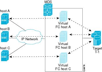
When an iSCSI host connects to the Fibre Channel module with IPS ports or MPS-14/2 module, a virtual host N port (HBA port) is created for the host (see Figure 4-19). Every Fibre Channel N port requires a unique Node WWN and Port WWN.
Figure 4-19 Virtual Host HBA Port
After the virtual N port is created with the WWNs, a fabric login (FLOGI) is done through the virtual iSCSI interface of the IPS port. After the FLOGI is completed, the virtual N port is online in the Fibre Channel SAN and virtual N port is registered in the Fibre Channel name server. The Fibre Channel module with IPS ports or MPS-14/2 module registers the following entries in the Fibre Channel name server:
- IP address of the iSCSI host in the IP-address field on the name server
- IQN of the iSCSI host in the symbolic-node-name field of the name server
- SCSI_FCP in the FC-4 type field of the name server
- Initiator flag in the FC-4 feature of the name server
- Vendor-specific iSCSI GW flag in the FC-4 type field to identify the N-port device as an iSCSI gateway device in the name server.
When all the iSCSI sessions from the iSCSI host are terminated, the Fibre Channel module with IPS ports or MPS-14/2 modules perform an explicit Fabric logout (FLOGO) to remove the virtual N-port device from the Fibre Channel SAN (this indirectly de-registers the device from the Fibre Channel name server).
For every iSCSI session from the host to the iSCSI virtual target there is a corresponding Fibre Channel session to the real Fibre Channel target. There are three iSCSI hosts (see Figure 4-19), and all three of them connect to the same Fibre Channel target. There is one Fibre Channel session from each of the three virtual Fibre Channel hosts to the target.
iSCSI Initiator Idle Timeout
iSCSI initiator idle timeout specifies the time for which the virtual Fibre Channel N port is kept idle after the initiator logs out from its last iSCSI session. The default value for this timer is 300 seconds. This is useful to avoid N ports logging in to and logging off of the Fibre Channel SAN as transient failure occurs in the IP network. This helps reduce unnecessary RSCNs being generated in the Fibre Channel SAN.
To configure the initiator idle timeout, follow these steps:
|
|
|
|
|---|---|---|
Configures the iSCSI initiators to have an idle timeout value of 10 seconds. |
To configure the initiator idle timeout using Fabric Manager, follow these steps:
Step 1![]() Choose End Devices > iSCSI in the Physical Attributes pane.
Choose End Devices > iSCSI in the Physical Attributes pane.
You see the iSCSI tables in the Information pane (see Figure 4-5).
You see the iSCSI global configuration.
Step 3![]() Right-click on the InitiatorIdle Timeout field that you want to modify and enter the new timeout value.
Right-click on the InitiatorIdle Timeout field that you want to modify and enter the new timeout value.
Step 4![]() Click the Apply Changes icon to save these changes.
Click the Apply Changes icon to save these changes.
WWN Assignment for iSCSI Initiators
An iSCSI host is mapped to an N port’s WWNs by one of the following mechanisms:
With dynamic mapping, an iSCSI host is mapped to a dynamically generated port WWN (pWWN) and node WWN (nWWN). Each time the iSCSI host connects it might be mapped to a different WWN. Use this option if no access control is required on the Fibre Channel target device (because the target device access control is usually configured using the host WWN).
The WWNs are allocated from the MDS switch's WWN pool. The WWN mapping to the iSCSI host is maintained as long as the iSCSI host has at least one iSCSI session to the IPS port. When all iSCSI sessions from the host are terminated and the Fibre Channel module with IPS ports or MPS-14/2 module performs an FLOGO for the virtual N port of the host, the WWNs are released back to the switch's Fibre Channel WWN pool. These addresses are then available for assignment to other iSCSI hosts requiring access to the Fibre Channel Fabric.
The following are three dynamic initiator modes are supported:
- iSCSI—Dynamic initiators are treated as iSCSI initiators and can access dynamic virtual targets and configured iSCSI virtual targets.
- iSLB—Dynamic initiators are treated as iSLB initiators.
- Deny—Dynamic initiators are not allowed to log in to the MDS switch.
iSCSI dynamic mapping is the default mode of operation. This configuration is distributed using CFS.
Note![]() Configuring dynamic initiator modes is supported only through the CLI, not through Device Manager or Fabric Manager.
Configuring dynamic initiator modes is supported only through the CLI, not through Device Manager or Fabric Manager.
To configure dynamic mapping (using the name option) for an iSCSI initiator, follow these steps:
|
|
|
|
|---|---|---|
Disallows dynamic initiators from logging on to the MDS switch. |
||
With static mapping, an iSCSI host is mapped to a specific pWWN and nWWN. This mapping is maintained in persistent storage and each time the iSCSI host connects, the same WWN mapping is used. This mode is required if you use access control on the target device.
You can implement static mapping in one of two ways:
- User assignment—You can specify your own unique WWN by providing them during the configuration process.
- System assignment—You can request that the switch provide a WWN from the switch’s Fibre Channel WWN pool and keep the mapping in its configuration.
Tip We recommend using the system-assign option. If you manually assign a WWN, you must ensure its uniqueness (see the Cisco Fabric Manager Fabric Configuration Guide and Cisco MDS 9000 Family NX-OS Fabric Configuration Guide for more information). You should not use any previously assigned WWNs.
To configure static mapping (using the name option) for an iSCSI initiator, follow these steps:
To configure static mapping for an iSCSI initiator using Device Manager, follow these steps:
You see the iSCSI configuration (see Figure 4-12). The Initiators tab is the default.
Step 2![]() Click Create to create an iSCSI initiator.
Click Create to create an iSCSI initiator.
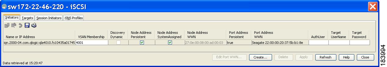
You see the Create iSCSI Initiators dialog box (see Figure 4-20).
Figure 4-20 Create iSCSI Initiators Dialog Box
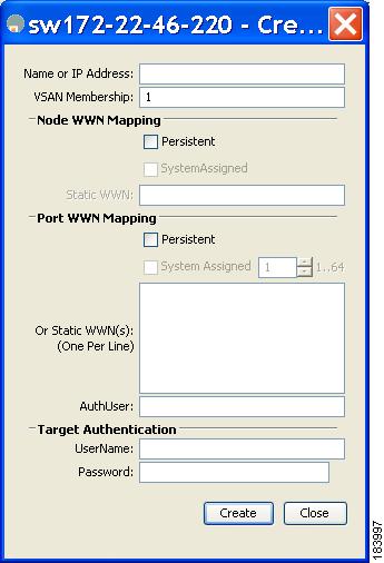
Step 3![]() Set the iSCSI node name or IP address and VSAN membership.
Set the iSCSI node name or IP address and VSAN membership.
Step 4![]() In the Node WWN section, check the Persistent check box.
In the Node WWN section, check the Persistent check box.
Step 5![]() Check the System Assigned check box if you want the switch to assign the nWWN or leave this unchecked and set the Static WWN field.
Check the System Assigned check box if you want the switch to assign the nWWN or leave this unchecked and set the Static WWN field.
Step 6![]() In the Port WWN section, check the Persistent check box if you want to statically map pWWNs to the iSCSI initiator.
In the Port WWN section, check the Persistent check box if you want to statically map pWWNs to the iSCSI initiator.
Step 7![]() If persistent, check the System Assigned check box and set the number of pWWNs to reserve for this iSCSI initiator if you want the switch to assign pWWNs. Alternately, you can leave this unchecked and set one or more pWWNs for this iSCSI initiator.
If persistent, check the System Assigned check box and set the number of pWWNs to reserve for this iSCSI initiator if you want the switch to assign pWWNs. Alternately, you can leave this unchecked and set one or more pWWNs for this iSCSI initiator.
Step 8![]() (Optional) Set the AuthUser field if authentication is enabled. Also see the “iSCSI Session Authentication” section.
(Optional) Set the AuthUser field if authentication is enabled. Also see the “iSCSI Session Authentication” section.
Step 9![]() Click Create to create this iSCSI initiator.
Click Create to create this iSCSI initiator.
To configure static mapping (using the ip-address option) for an iSCSI initiator, follow these steps:
To assign the WWN for an iSCSI initiator, follow these steps:
Note![]() If the system-assign option is used to configure WWNs for an iSCSI initiator, when the configuration is saved to an ASCII file the system-assigned WWNs are also saved. Subsequently if you perform a write erase, you must manually delete the WWN configuration from the ASCII file. Failing to do so can cause duplicate WWN assignments if the ASCII configuration file is reapplied on the switch.
If the system-assign option is used to configure WWNs for an iSCSI initiator, when the configuration is saved to an ASCII file the system-assigned WWNs are also saved. Subsequently if you perform a write erase, you must manually delete the WWN configuration from the ASCII file. Failing to do so can cause duplicate WWN assignments if the ASCII configuration file is reapplied on the switch.
Making the Dynamic iSCSI Initiator WWN Mapping Static
After a dynamic iSCSI initiator has already logged in, you may decide to permanently keep the automatically assigned nWWN/pWWN mapping so this initiator uses the same mapping the next time it logs in.
You can convert a dynamic iSCSI initiator to static iSCSI initiator and make its WWNs persistent (see the “Dynamic Mapping” section).
Note![]() You cannot convert a dynamic iSCSI initiator to a static iSLB initiator or a dynamic iSLB initiator to a static iSCSI initiator.
You cannot convert a dynamic iSCSI initiator to a static iSLB initiator or a dynamic iSLB initiator to a static iSCSI initiator.
Note![]() Making the dynamic pWWNs static after the initiator is created is supported only through the CLI, not through Device Manager or Fabric Manager. In Fabric Manager or Device Manager, you must delete and then recreate this initiator to have the pWWNs static.
Making the dynamic pWWNs static after the initiator is created is supported only through the CLI, not through Device Manager or Fabric Manager. In Fabric Manager or Device Manager, you must delete and then recreate this initiator to have the pWWNs static.
To permanently keep the automatically assigned nWWN/pWWN mapping, follow these steps:
WWNs assigned to static iSCSI initiators by the system can be inadvertently returned to the system when an upgrade fails or you downgrade the system software (manually booting up an older Cisco MDS SAN-OS release without using the install all command). In these instances, the system can later assign those WWNs to other iSCSI initiators (dynamic or static) and cause conflicts.
You can address this problem by checking for and removing any configured WWNs that belong to the system whenever such scenarios occur.
To check for and remove WWN conflicts, follow these steps:
To permanently keep the automatically assigned nWWN mapping using Fabric Manager, follow these steps:
Step 1![]() Choose End Devices > iSCSI in the Physical Attributes pane.
Choose End Devices > iSCSI in the Physical Attributes pane.
You see the iSCSI tables in the Information pane (see Figure 4-5).
Step 2![]() Click the Initiators tab.
Click the Initiators tab.
You see the iSCSI initiators configured.
Step 3![]() Check the Persistent Node WWN check box for the iSCSI initiators that you want to make static.
Check the Persistent Node WWN check box for the iSCSI initiators that you want to make static.
Step 4![]() Click the Apply Changes icon to save these changes.
Click the Apply Changes icon to save these changes.
Proxy Initiator Mode
In the event that the Fibre Channel storage device requires explicit LUN access control for every host use the transparent initiator mode (presenting one iSCSI host as one Fibre Channel host). Every iSCSI host has to be configured statically. This can mean several configuration tasks for each iSCSI host. If you do not need explicit LUN access control, using the proxy initiator mode simplifies the configuration.
In this mode, only one virtual host N port (HBA port) is created per IPS port. All the iSCSI hosts connecting to that IPS port will be multiplexed using the same virtual host N port (see Figure 4-21). This mode simplifies the task of statically binding WWNs. LUN mapping and assignment on the Fibre Channel storage array must be configured to allow access from the proxy virtual N port’s pWWN for all LUNs used by each iSCSI initiator that connects through this IPS port. The LUN is then assigned to each iSCSI initiator by configuring iSCSI virtual targets (see the “Static Mapping” section) with LUN mapping and iSCSI access control (see the “iSCSI Access Control” section).
Figure 4-21 Multiplexing IPS Ports
Proxy initiator mode can be configured on a per IPS port basis, in which case only iSCSI initiators terminating on that IPS port will be in this mode.
When an IPS port is configured in proxy-initiator mode, fabric login (FLOGI) is done through the virtual iSCSI interface of the IPS port. After the FLOGI is completed, the proxy-initiator virtual N port is online in the Fibre Channel fabric and virtual N port is registered in the Fibre Channel name server. The Fibre Channel module with IPS ports or MPS-14/2 module registers the following entries in the Fibre Channel name server:
- iSCSI interface name iSCSI slot /port is registered in the symbolic-node-name field of the name server
- SCSI_FCP in the FC-4 type field of the name server
- Initiator flag in the FC-4 feature of the name server
- Vendor specific flag (iscsi-gw) in the FC-4 type field to identify the N-port device as an iSCSI gateway device in the name server
Similar to transparent initiator mode, the user can provide a pWWN and nWWN or request a system assigned WWN for the proxy initiator N port.
To configure the proxy initiator, follow these steps:
To configure the proxy initiator using Fabric Manager, follow these steps:
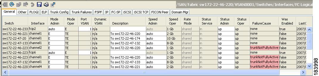
Step 1![]() Expand Switches, expand Interfaces, and then select FC Logical in the Physical Attributes pane.
Expand Switches, expand Interfaces, and then select FC Logical in the Physical Attributes pane.
You see the Interface tables in the Information pane (see Figure 4-22).
Figure 4-22 FC Logical Interface Tables
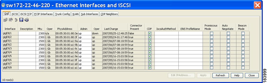
Step 2![]() In Device Manager, select Interface > Ethernet and iSCSI.
In Device Manager, select Interface > Ethernet and iSCSI.
You see the Ethernet Interfaces and iSCSI dialog box (See in Figure 4-23).
Figure 4-23 Ethernet Interfaces and iSCSI Dialog Box
Step 3![]() Click the iSCSI tab in either FM or DM.
Click the iSCSI tab in either FM or DM.
You see the iSCSI interface configuration table (see Figure 4-24).
Figure 4-24 iSCSI Tab in Device Manager
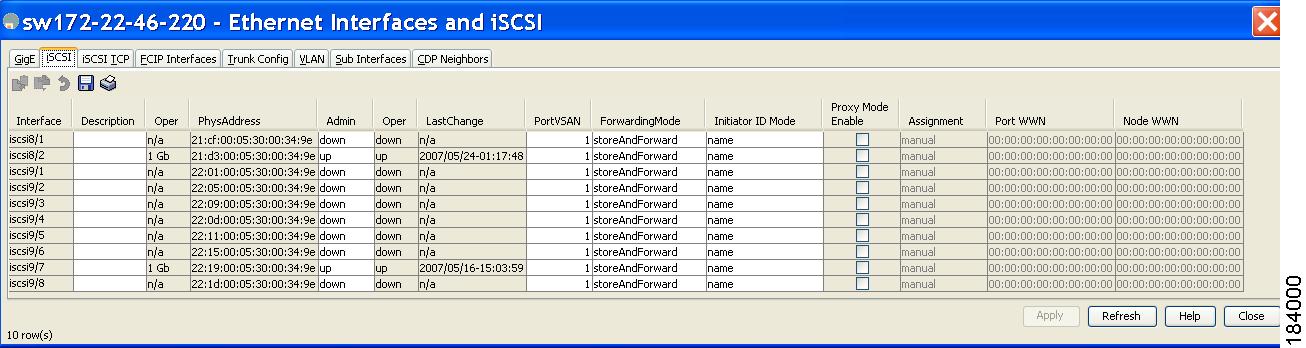
Step 4![]() Check the Proxy Mode Enable check box.
Check the Proxy Mode Enable check box.
Step 5![]() Click the Apply Changes icon in Fabric Manager or click Apply in Device Manager to save these changes.
Click the Apply Changes icon in Fabric Manager or click Apply in Device Manager to save these changes.
Note![]() When an interface is in proxy initiator mode, you can only configure Fibre Channel access control (zoning) based on the iSCSI interface’s proxy N port attributes—the WWN pairs or the FC ID. You cannot configure zoning using iSCSI attributes such as IP address or IQN of the iSCSI initiator. To enforce initiator-based access control, use iSCSI based access control (see the “iSCSI Access Control” section).
When an interface is in proxy initiator mode, you can only configure Fibre Channel access control (zoning) based on the iSCSI interface’s proxy N port attributes—the WWN pairs or the FC ID. You cannot configure zoning using iSCSI attributes such as IP address or IQN of the iSCSI initiator. To enforce initiator-based access control, use iSCSI based access control (see the “iSCSI Access Control” section).
VSAN Membership for iSCSI
VSAN membership can be configured for an iSCSI interface, called the port VSAN. All the iSCSI devices that connect to this interface automatically become members of this VSAN, if it is not explicitly configured in a VSAN. The default port VSAN of an iSCSI interface is VSAN 1. Similar to Fibre Channel devices, iSCSI devices have two mechanisms by which VSAN membership can be defined.
- iSCSI host—VSAN membership to iSCSI host. (This method takes precedent over the iSCSI interface).
- iSCSI interface—VSAN membership to iSCSI interface. (All iSCSI hosts connecting to this iSCSI interface inherit the interface VSAN membership if the host is not configured in any VSAN by the iSCSI host method).
Configuring VSAN Membership for iSCSI Hosts
Individual iSCSI hosts can be configured to be in a specific VSAN. The specified VSAN overrides the iSCSI interface VSAN membership.
To assign VSAN membership for iSCSI hosts, follow these steps:
|
|
|
|
|---|---|---|
switch(config)# iscsi initiator name iqn.1987-02.com.cisco.initiator |
||
To assign VSAN membership for iSCSI hosts using Fabric Manager, follow these steps:
Step 1![]() Choose End Devices > iSCSI in the Physical Attributes pane.
Choose End Devices > iSCSI in the Physical Attributes pane.
You see the iSCSI tables in the Information pane (see Figure 4-5).
Step 2![]() Click the Initiators tab.
Click the Initiators tab.
You see the iSCSI initiators configured.
Step 3![]() Fill in the VSAN Membership field to assign a VSAN to the iSCSI hosts.
Fill in the VSAN Membership field to assign a VSAN to the iSCSI hosts.
Step 4![]() Click the Apply Changes icon to save these changes.
Click the Apply Changes icon to save these changes.
Note![]() When an initiator is configured in any other VSAN (other than VSAN 1), for example VSAN 2, the initiator is automatically removed from VSAN 1. If you also want it to be present in VSAN 1, you must explicitly configure the initiator in VSAN 1.
When an initiator is configured in any other VSAN (other than VSAN 1), for example VSAN 2, the initiator is automatically removed from VSAN 1. If you also want it to be present in VSAN 1, you must explicitly configure the initiator in VSAN 1.
Configuring Default Port VSAN for iSCSI Interfaces
VSAN membership can be configured for an iSCSI interface, called the port VSAN. All the iSCSI devices that connect to this interface automatically become members of this VSAN, if it is not explicitly configured in a VSAN. In other words, the port VSAN of an iSCSI interface is the default VSAN for all dynamic iSCSI initiators. The default port VSAN of an iSCSI interface is VSAN 1.
To change the default port VSAN for an iSCSI interface, follow these steps:
To change the default port VSAN for an iSCSI interface using Device Manager, follow these steps:
Step 1![]() Choose Interface > Ethernet and iSCSI.
Choose Interface > Ethernet and iSCSI.
You see the Ethernet Interfaces and iSCSI dialog box (see Figure 4-23).
You see the iSCSI interface configuration table (see Figure 4-24).
Step 3![]() Double-click the PortVSAN column and modify the default port VSAN.
Double-click the PortVSAN column and modify the default port VSAN.
Step 4![]() Click Apply to save these changes.
Click Apply to save these changes.
Example of VSAN Membership for iSCSI Devices
Figure 4-25 provides an example of VSAN membership for iSCSI devices:
- iSCSI interface 1/1 is a member of VSAN Y.
- iSCSI initiator host A has explicit VSAN membership to VSAN X.
- Three iSCSI initiators (host A, host B, and host C) C connect to iSCSI interface 1/1.
Figure 4-25 VSAN Membership for iSCSI Interfaces
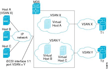
Host A’s virtual Fibre Channel N port will be added to VSAN X because of explicit membership for the initiator. The virtual host-B and host-C N ports do not have any explicit membership configuration so they will inherit the iSCSI interface VSAN membership and be part of VSAN Y.
Advanced VSAN Membership for iSCSI Hosts
An iSCSI host can be a member of multiple VSANs. In this case, multiple virtual Fibre Channel hosts are created, one in each VSAN in which the iSCSI host is a member. This configuration is useful when certain resources such as Fibre Channel tape devices need to be shared among different VSANs.
iSCSI Access Control
Two methods of access control are available for iSCSI devices. Depending on the initiator mode used to present the iSCSI hosts in the Fibre Channel fabric, either or both of the access control methods can be used.
- Fiber Channel zoning-based access control—Fibre Channel zoning has been extended to support iSCSI devices, and this extension has the advantage of having a uniform, flexible access control mechanism across the whole SAN. In the case of iSCSI, multiple iSCSI devices may be connected behind an iSCSI interface. Interface-based zoning may not be useful because all iSCSI devices behind the interface will automatically be within the same zone.
- iSCSI ACL-based access control—iSCSI-based access control is applicable only if static iSCSI virtual targets are created. For a static iSCSI target, you can configure a list of iSCSI initiators that are allowed to access the targets. By default, static iSCSI virtual targets are not accessible to any iSCSI host.
Depending on the initiator mode used to present the iSCSI hosts in the Fibre Channel fabric, either or both the access control mechanisms can be used.
Fibre Channel Zoning-Based Access Control
Cisco SAN-OS Release 3.x and NX-OS Release 4.1(1b) VSAN and zoning concepts have been extended to cover both Fibre Channel devices and iSCSI devices. Zoning is the standard access control mechanism for Fibre Channel devices, which is applied within the context of a VSAN. Fibre Channel zoning has been extended to support iSCSI devices, and this extension has the advantage of having a uniform, flexible access control mechanism across the whole SAN.
Common mechanisms for identifying members of a Fibre Channel zone are the following:
- Fibre Channel device pWWN.
- Interface and switch WWN. Device connecting via that interface is within the zone.
See the Cisco Fabric Manager Fabric Configuration Guide and Cisco MDS 9000 Family NX-OS Fabric Configuration Guide for details on Fibre Channel zoning.
In the case of iSCSI, multiple iSCSI devices may be connected behind an iSCSI interface. Interface-based zoning may not be useful because all the iSCSI devices behind the interface will automatically be within the same zone.
In transparent initiator mode (where one Fibre Channel virtual N port is created for each iSCSI host as described in the “Transparent Initiator Mode” section), if an iSCSI host has static WWN mapping then the standard Fibre Channel device pWWN-based zoning membership mechanism can be used.
Zoning membership mechanism has been enhanced to add iSCSI devices to zones based on the following:
- IPv4 address/subnet mask
- IPv6 address/prefix length
- iSCSI qualified name (IQN)
- Symbolic-node-name (IQN)
For iSCSI hosts that do not have a static WWN mapping, the feature allows the IP address or iSCSI node name to be specified as zone members. Note that iSCSI hosts that have static WWN mapping can also use these features. IP address based zone membership allows multiple devices to be specified in one command by providing the subnet mask.
Note![]() In proxy initiator mode, all iSCSI devices connecting to an IPS port gain access to the Fibre Channel fabric through a single virtual Fibre Channel N port. Zoning based on the iSCSI node name or IP address will not have any effect. If zoning based on pWWN is used, then all iSCSI devices connecting to that IPS port will be put in the same zone. To implement individual initiator access control in proxy initiator mode, configure an iSCSI ACL on the virtual target (see the “iSCSI-Based Access Control” section).
In proxy initiator mode, all iSCSI devices connecting to an IPS port gain access to the Fibre Channel fabric through a single virtual Fibre Channel N port. Zoning based on the iSCSI node name or IP address will not have any effect. If zoning based on pWWN is used, then all iSCSI devices connecting to that IPS port will be put in the same zone. To implement individual initiator access control in proxy initiator mode, configure an iSCSI ACL on the virtual target (see the “iSCSI-Based Access Control” section).
To add an iSCSI initiator to the zone database, follow these steps:
To add an iSCSI initiator to the zone database using Fabric Manager, follow these steps:
Step 1![]() Choose Zone > Edit Local Full Zone Database.
Choose Zone > Edit Local Full Zone Database.
You see the Edit Local Zone Database dialog box (see Figure 4-26).
Figure 4-26 Edit Local Zone Database Dialog Box in Fabric Manager
Step 2![]() Select the VSAN you want to add the iSCSI host initiator to and click OK.
Select the VSAN you want to add the iSCSI host initiator to and click OK.
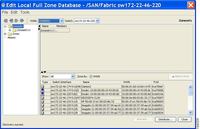
You see the available zones and zone sets for that VSAN (see Figure 4-27).
Figure 4-27 Available Zones and Zone Sets
Step 3![]() From the list of available devices with iSCSI host initiators, drag the initiators to add into the zone.
From the list of available devices with iSCSI host initiators, drag the initiators to add into the zone.
Step 4![]() Click Distribute to distribute the change.
Click Distribute to distribute the change.
iSCSI-Based Access Control
iSCSI-based access control is applicable only if static iSCSI virtual targets are created (see the “Static Mapping” section). For a static iSCSI target, you can configure a list of iSCSI initiators that are allowed to access the targets.
By default, static iSCSI virtual targets are not accessible to any iSCSI host. You must explicitly configure accessibility to allow an iSCSI virtual target to be accessed by all hosts. The initiator access list can contain one or more initiators. The iSCSI initiator can be identified by one of the following mechanisms:
Note![]() For a transparent mode iSCSI initiator, if both Fibre Channel zoning and iSCSI ACLs are used, then for every static iSCSI target that is accessible to the iSCSI host, the initiator’s virtual N port should be in the same Fibre Channel zone as the Fibre Channel target.
For a transparent mode iSCSI initiator, if both Fibre Channel zoning and iSCSI ACLs are used, then for every static iSCSI target that is accessible to the iSCSI host, the initiator’s virtual N port should be in the same Fibre Channel zone as the Fibre Channel target.
To configure access control in iSCSI follow these steps:
To configure access control in iSCSI using Device Manager, follow these steps:
You see the iSCSI configuration (see Figure 4-12).
You see the iSCSI virtual targets.
Step 3![]() Uncheck the Initiators Access All check box if checked.
Uncheck the Initiators Access All check box if checked.
You see the Initiators Access dialog box.
Step 5![]() Click Create to add more initiators to the Initiator Access list.
Click Create to add more initiators to the Initiator Access list.
You see the Create Initiators Access dialog box.
Step 6![]() Add the name or IP address for the initiator that you want to permit for this virtual target.
Add the name or IP address for the initiator that you want to permit for this virtual target.
Step 7![]() Click Create to add this initiator to the Initiator Access List.
Click Create to add this initiator to the Initiator Access List.
Enforcing Access Control
Fibre Channel module with IPS ports and MPS-14/2 modules use both iSCSI and Fibre Channel zoning-based access control lists to enforce access control. Access control is enforced both during the iSCSI discovery phase and the iSCSI session creation phase. Access control enforcement is not required during the I/O phase because the Fibre Channel module with IPS ports or MPS-14/2 module is responsible for the routing of iSCSI traffic to Fibre Channel.
- iSCSI discovery phase—When an iSCSI host creates an iSCSI discovery session and queries for all iSCSI targets, the Fibre Channel module with IPS ports or MPS-14/2 module returns only the list of iSCSI targets this iSCSI host is allowed to access based on the access control policies discussed in the previous section. The Fibre Channel module with IPS ports or MPS-14/2 module does this by querying the Fibre Channel name server for all the devices in the same zone as the initiator in all VSANs. It then filters out the devices that are initiators by looking at the FC4-feature field of the FCNS entry. (If a device does not register as either initiator or target in the FC4-feature field, the Fibre Channel module with IPS ports or MPS-14/2 module will advertise it). It then responds to the iSCSI host with the list of targets. Each will have either a static iSCSI target name that you configure or a dynamic iSCSI target name that the Fibre Channel module with IPS ports or MPS-14/2 module creates for it (see the “Dynamic Mapping” section).
- iSCSI session creation—When an IP host initiates an iSCSI session, the Fibre Channel module with IPS ports or MPS-14/2 module verifies if the specified iSCSI target (in the session login request) is allowed by both the access control mechanisms described in the “iSCSI-Based Access Control” section.
If the iSCSI target is a static mapped target, the Fibre Channel module with IPS ports or MPS-14/2 module verifies if the iSCSI host is allowed within the access list of the iSCSI target. If the IP host does not have access, its login is rejected. If the iSCSI host is allowed, it validates if the virtual Fibre Channel N port used by the iSCSI host and the Fibre Channel target mapped to the static iSCSI virtual target are in the same Fibre Channel zone.
If the iSCSI target is an autogenerated iSCSI target, then the Fibre Channel module with IPS ports or MPS-14/2 module extracts the WWN of the Fibre Channel target from the iSCSI target name and verifies if the initiator and the Fibre Channel target is in the same Fibre Channel zone or not. If they are, then access is allowed.
The Fibre Channel module with IPS ports or MPS-14/2 module uses the Fibre Channel virtual N port of the iSCSI host and does a zone-enforced name server query for the Fibre Channel target WWN. If the FC ID is returned by the name server, then the iSCSI session is accepted. Otherwise, the login request is rejected.
iSCSI Session Authentication
The Fibre Channel module with IPS ports or MPS-14/2 module supports the iSCSI authentication mechanism to authenticate the iSCSI hosts that request access to the storage devices. By default, the Fibre Channel module with IPS ports or MPS-14/2 modules allow CHAP or None authentication of iSCSI initiators. If authentication is always used, you must configure the switch to allow only CHAP authentication.
For CHAP user name or secret validation, you can use any method supported and allowed by the Cisco MDS AAA infrastructure. AAA authentication supports a RADIUS, TACACS+, or local authentication device. See the Cisco Fabric Manager Security Configuration Guide.
The aaa authentication iscsi command enables AAA authentication for the iSCSI host and specifies the method to use. See Cisco MDS 9000 Family NX-OS Security Configuration Guide
To configure AAA authentication for an iSCSI user, follow these steps:
To configure AAA authentication for an iSCSI user using Fabric Manager, follow these steps:
Step 1![]() Choose Switches > Security > AAA in the Physical Attributes pane.
Choose Switches > Security > AAA in the Physical Attributes pane.
You see the AAA configuration in the Information pane.
Step 2![]() Click the Applications tab.
Click the Applications tab.
You see the AAA configuration per application (see Figure 4-28).
Figure 4-28 AAA per Application Configuration
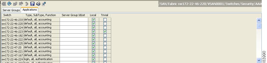
Step 3![]() Right-click the ServerGroup Id List field for the iSCSI application and enter the server group that you want iSCSI to use.
Right-click the ServerGroup Id List field for the iSCSI application and enter the server group that you want iSCSI to use.
Note![]() You should use an existing server group or create a new server group before configuring it for iSCSI session authentication.
You should use an existing server group or create a new server group before configuring it for iSCSI session authentication.
Step 4![]() Click the Apply Changes icon to save these changes.
Click the Apply Changes icon to save these changes.
Configuring Authentication Mechanism
You can configure iSCSI CHAP or None authentication at both the global level and at each interface level.
The authentication for a Gigabit Ethernet interface or subinterface overrides the authentication method configured at the global level.
If CHAP authentication is used, issue the iscsi authentication chap command at either the global level or at a per-interface level. If authentication should not be used at all, issue the iscsi authentication none command.
To configure the authentication mechanism for iSCSI, follow these steps:
|
|
|
|
|---|---|---|
Configures CHAP as the default authentication mechanism globally for the Cisco MDS switch. CHAP authentication is required for all iSCSI sessions. |
To configure AAA authentication for an iSCSI user using Fabric Manager, follow these steps:
Step 1![]() Choose End Devices > iSCSI in the Physical Attributes pane.
Choose End Devices > iSCSI in the Physical Attributes pane.
You see the iSCSI tables in the Information pane (see Figure 4-5).
You see the iSCSI authentication configuration table.
Step 3![]() Select chap or none from the authMethod column.
Select chap or none from the authMethod column.
Step 4![]() Click the Apply Changes icon in Fabric Manager to save these changes.
Click the Apply Changes icon in Fabric Manager to save these changes.
To configure the authentication mechanism for iSCSI sessions to a particular interface, follow these steps:
|
|
|
|
|---|---|---|
Specifies that no authentication is required for iSCSI sessions to the selected interface. |
To configure the authentication mechanism for iSCSI sessions to a particular interface using Fabric Manager, follow these steps:
Step 1![]() Choose Switches > Interfaces > Gigabit Ethernet in the Physical Attributes pane.
Choose Switches > Interfaces > Gigabit Ethernet in the Physical Attributes pane.
You see the Gigabit Ethernet configuration in the Information pane.
You see the iSCSI and iSNS configuration (see Figure 4-29).
Figure 4-29 Configuring iSCSI Authentication on an Interface
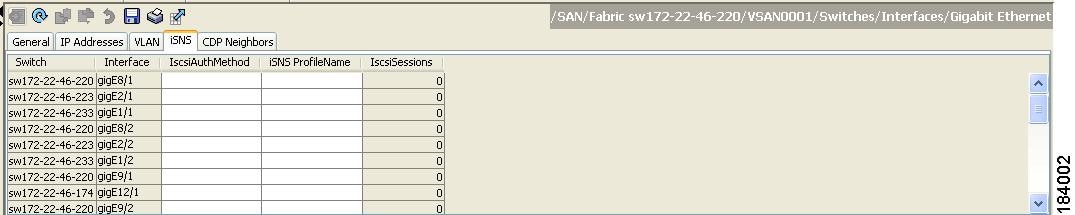
Step 3![]() Right-click on the IscsiAuthMethod field and select none or chap.
Right-click on the IscsiAuthMethod field and select none or chap.
Step 4![]() Click the Apply Changes icon to save these changes.
Click the Apply Changes icon to save these changes.
Configuring Local Authentication
See the Cisco Fabric Manager Security Configuration Guide and Cisco MDS 9000 Family NX-OS Security Guide to create the local password database. To create users in the local password database for the iSCSI initiator, the iSCSI keyword is mandatory.
To configure iSCSI users for local authentication, follow these steps:
To configure iSCSI users for local authentication using Device Manager, follow these steps:
Step 1![]() Choose Security > iSCSI.
Choose Security > iSCSI.
You see the iSCSI Security dialog box (see Figure 4-30).
Figure 4-30 iSCSI Security Dialog Box
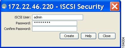
Step 2![]() Complete the iSCSI User, Password, and Password Confirmation fields.
Complete the iSCSI User, Password, and Password Confirmation fields.
Step 3![]() Click Create to save this new user.
Click Create to save this new user.
Restricting iSCSI Initiator Authentication
By default, the iSCSI initiator can use any user name in the RADIUS server or in the local database in authenticating itself to the Fibre Channel module with IPS ports or MPS-14/2 module (the CHAP user name is independent of the iSCSI initiator name). The Fibre Channel module with IPS ports or MPS-14/2 module allows the initiator to log in as long as it provides a correct response to the CHAP challenge sent by the switch. This can be a problem if one CHAP user name and password has been compromised.
To restrict an initiator to use a specific user name for CHAP authentication, follow these steps:
To restrict an initiator to use a specific user name for CHAP authentication using Fabric Manager, follow these steps:
Step 1![]() Choose End Devices > iSCSI in the Physical Attributes pane.
Choose End Devices > iSCSI in the Physical Attributes pane.
You see the iSCSI tables in the Information pane (see Figure 4-5).
Step 2![]() Right-click the AuthUser field and enter the user name to which you want to restrict the iSCSI initiator.
Right-click the AuthUser field and enter the user name to which you want to restrict the iSCSI initiator.
Step 3![]() Click the Apply Changes icon to save these changes.
Click the Apply Changes icon to save these changes.
Configuring Mutual CHAP Authentication
The Fibre Channel module with IPS ports or MPS-14/2 module supports a mechanism by which the iSCSI initiator can authenticate the Cisco MDS switch’s iSCSI target during the iSCSI login phase. This authentication is available in addition to the Fibre Channel module with IPS ports or MPS-14/2 module authentication of the iSCSI initiator.
In addition to the Fibre Channel module with IPS ports or MPS-14/2 module authentication of the iSCSI initiator, the Fibre Channel module with IPS ports or MPS-14/2 module also supports a mechanism for the iSCSI initiator to authenticate the Cisco MDS switch’s iSCSI target during the iSCSI login phase. This authentication requires the user to configure a user name and password for the switch to present to the iSCSI initiator. The provided password is used to calculate a CHAP response to a CHAP challenge sent to the IPS port by the initiator.
To configure a global iSCSI target user name and password to be used by the switch to authenticate itself to an initiator, follow these steps:
To configure a global iSCSI target user name and password to be used by the switch to authenticate itself to an initiator using Fabric Manager, follow these steps:
Step 1![]() Choose End Devices > iSCSI in the Physical Attributes pane.
Choose End Devices > iSCSI in the Physical Attributes pane.
You see the iSCSI tables in the Information pane (see Figure 4-5).
Step 2![]() Select the Globals tab.
Select the Globals tab.
You see the global iSCSI configuration.
Step 3![]() Fill in the Target UserName and Target Password fields.
Fill in the Target UserName and Target Password fields.
Step 4![]() Click the Apply Changes icon to save these changes.
Click the Apply Changes icon to save these changes.
To configure a per-initiator iSCSI target’s user name and password used by the switch to authenticate itself to an initiator, follow these steps:
Use the show running-config and the show iscsi global commands to display the global configuration. Use the show running-config and the show iscsi initiator configured commands to display the initiator specific configuration.(See the “Displaying iSCSI Information” section for command output examples).
To configure a per-initiator iSCSI target’s user name and password used by the switch to authenticate itself to an initiator using Device Manager, follow these steps:
You see the iSCSI configuration (see Figure 4-12).
Step 2![]() Complete the Target UserName and Target Password fields for the initiator that you want to configure.
Complete the Target UserName and Target Password fields for the initiator that you want to configure.
Step 3![]() Click Create to add this initiator to the Initiator Access List.
Click Create to add this initiator to the Initiator Access List.
Configuring an iSCSI RADIUS Server
To configure an iSCSI RADIUS server, follow these steps:
Step 1![]() Configure the RADIUS server to allow access from the Cisco MDS switch's management Ethernet IP address.
Configure the RADIUS server to allow access from the Cisco MDS switch's management Ethernet IP address.
Step 2![]() Configure the shared secret for the RADIUS server to authenticate the Cisco MDS switch.
Configure the shared secret for the RADIUS server to authenticate the Cisco MDS switch.
Step 3![]() Configure the iSCSI users and passwords on the RADIUS server.
Configure the iSCSI users and passwords on the RADIUS server.
iSCSI Immediate Data and Unsolicited Data Features
Cisco MDS switches support the iSCSI immediate data and unsolicited data features if requested by the initiator during the login negotiation phase. Immediate data is iSCSI write data contained in the data segment of an iSCSI command protocol data unit (PDU), such as combining the write command and write data together in one PDU. Unsolicited data is iSCSI write data that an initiator sends to the iSCSI target, such as an MDS switch, in an iSCSI data-out PDU without having to receive an explicit ready to transfer (R2T) PDU from the target.
These two features help reduce I/O time for small write commands because it removes one round-trip between the initiator and the target for the R2T PDU. As an iSCSI target, the MDS switch allows up to 64 KB of unsolicited data per command. This is controlled by the FirstBurstLength parameter during iSCSI login negotiation phase.
If an iSCSI initiator supports immediate data and unsolicited data features, these features are automatically enabled on the MDS switch with no configuration required.
iSCSI Interface Advanced Features
Advanced configuration options are available for iSCSI interfaces on a per-IPS port basis. These configurations are similar to the advanced FCIP configurations and are already explained in that section (see Advanced FCIP Profile Configuration for more information).
To access these commands from the iSCSI interface, follow these steps:
|
|
|
|
|---|---|---|
|
|
||
|
|
Cisco MDS switches support the following advanced features for iSCSI interfaces:
iSCSI Listener Port
You can configure the TCP port number for the iSCSI interface that listens for new TCP connections. The default port number is 3260. Once you change the TCP port number, the iSCSI port only accepts TCP connections on the newly configured port.
TCP Tuning Parameters
You can configure the following TCP parameters:
- Minimum retransmit timeout (See the “Minimum Retransmit Timeout” section for more information).
- Keepalive timeout (See the“Keepalive Timeout” section for more information).
- Maximum retransmissions (See the“Maximum Retransmissions” section for more information).
- Path MTU (See the “Path MTUs” section for more information).
- SACK (SACK is enabled by default for iSCSI TCP configurations).
- Window management (The iSCSI defaults are max-bandwidth is 1 Gbps, min-available-bandwidth is 70 Mbps, and round-trip-time is 1 msec). (See the “Window Management” section for more information).
- Buffer size (The iSCSI default send buffer size is 4096 KB) (See the “Displaying FCIP Profile Information” section for more information).
- Window congestion monitoring (enabled by default and the default burst size is 50 KB) (See the “Monitoring Congestion” section for more information).
- Maximum delay jitter (enabled by default and the default time is 500 microseconds).
Setting QoS Values
To set the QoS values, follow these steps:
To set the QoS values using Fabric Manager, follow these steps:
Step 1![]() Expand Switches, expand Interfaces and then select FC Logical in the Physical Attributes pane.
Expand Switches, expand Interfaces and then select FC Logical in the Physical Attributes pane.
You see the Interface tables in the Information pane (see Figure 4-22).
Step 2![]() In Device Manager, choose Interface > Ethernet and iSCSI.
In Device Manager, choose Interface > Ethernet and iSCSI.
You see the Ethernet Interfaces and iSCSI dialog box (see Figure 4-23).
Step 3![]() Click the iSCSI TCP tab in either Fabric Manager or Device Manager.
Click the iSCSI TCP tab in either Fabric Manager or Device Manager.
You see the iSCSI TCP configuration table.
Step 4![]() Set the QoS field from 1 to 6.
Set the QoS field from 1 to 6.
Step 5![]() Click the Apply Changes icon in Fabric Manager or click Apply in Device Manager to save these changes.
Click the Apply Changes icon in Fabric Manager or click Apply in Device Manager to save these changes.
iSCSI Routing Modes
Cisco MDS 9000 Family switches support multiple iSCSI routing modes. Each mode negotiates different operational parameters, has different advantages and disadvantages, and is suitable for different usages.
In pass-thru mode, the port on the Fibre Channel module with IPS ports or MPS 14/2 module converts and forwards read data frames from the Fibre Channel target to the iSCSI host frame-by-frame without buffering. This means that one data-in frame received is immediately sent out as one iSCSI data-in PDU.
In the opposite direction, the port on the Fibre Channel module with IPS ports or MPS 14/2 module limits the maximum size of iSCSI write data-out PDU that the iSCSI host can send to the maximum data size that the Fibre Channel target specifies that it can receive. The result is one iSCSI data-out PDU received sent out as one Fibre Channel data frame to the Fibre Channel target.
The absence of buffering in both directions leads to an advantage of lower forwarding latency. However, a small maximum data segment length usually results in lower data transfer performance from the host because of a higher processing overhead by the host system. Another benefit of this mode is iSCSI data digest can be enabled. This helps protect the integrity of iSCSI data carried in the PDU over what TCP checksum offers.
In store-and-forward mode, the port on the Fibre Channel module with IPS ports or MPS 14/2 module assembles all the Fibre Channel data frames of an exchange to build one large iSCSI data-in PDU before forwarding it to the iSCSI client.
In the opposite direction, the port on the Fibre Channel module with IPS ports or MPS 14/2 module does not impose a small data segment size on the host so the iSCSI host can send an iSCSI data-out PDU of any size (up to 256 KB). The port then waits until the whole iSCSI data-out PDU is received before it converts, or splits, the PDU, and forwards Fibre Channel frames to the Fibre Channel target.
The advantage of this mode is higher data transfer performance from the host. The disadvantages are higher transfer latency and that the iSCSI data digest (CRC) cannot be used.
Note![]() The store-and-forward mode is the default forwarding mode.
The store-and-forward mode is the default forwarding mode.
Cut-through mode improves the read operation performance over store-and-forward mode. The port on the Fibre Channel module with IPS ports or MPS 14/2 module achieves this by forwarding each Fibre Channel data-in frame to the iSCSI host as it is received without waiting for the whole exchange complete. There is no difference for write data-out operations from store-and-forward mode.
Figure 4-31 compares the messages exchanged by the iSCSI routing modes.
Figure 4-31 iSCSI Routing Modes
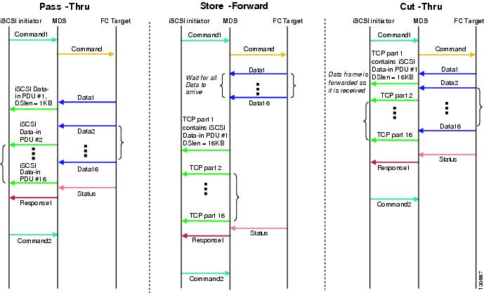
Table 4-1 compares the advantages and disadvantages of the different iSCSI routing modes.
Displaying iSCSI Information
Use the show iscsi command to obtain detailed information about iSCSI configurations.
Displaying iSCSI Interfaces
Use the show iscsi interface command to view the summary, counter, description, and status of the iSCSI interface. Use the output to verify the administrative mode, the interface status, TCP parameters currently used, and brief statistics.
Example 4-1 Displaying the iSCSI Interface Information
Displaying iSCSI Statistics
Use the show iscsi stats command to view brief or detailed iSCSI statistics per iSCSI interface. See Example 4-2 and Example 4-3.
Example 4-2 displays iSCSI throughput on an IPS port in both inbound and outbound directions. It also displays the number of different types of iSCSI PDU received and transmitted by this IPS port.
Example 4-2 Displaying Brief iSCSI Statistics for an iSCSI Interface
Example 4-3displays detailed iSCSI statistics for an IPS port. Along with the traffic rate and the number of each iSCSI PDU type, it shows the number of FCP frames received and forwarded, the number of iSCSI login attempts, successes, and failures. It also shows the number of different types of iSCSI PDUs sent and received that are noncritical or occur less frequently, such as NOP in and out (NOP-In and NOP-Out), text request and response (Text-REQ and Text-RESP), and task management request and response (TMF-REQ and TMF-RESP).
Various types of errors and PDU or frame drop occurrences are also counted and displayed. For example, Bad header digest shows the number of iSCSI PDUs received that have a header digest that fails CRC verification. The iSCSI Drop section shows the number of PDUs that were dropped because of reasons such as target down, LUN mapping fail, Data CRC error, or unexpected Immediate or Unsolicited data. These statistics are helpful for debugging purposes when the feature is not working as expected.
The last section, Buffer Stats, gives statistics on the internal IPS packet buffer operation. This section is for debugging purposes only.
Example 4-3 Displaying Detailed iSCSI Statistics for the iSCSI Interface
Displaying Proxy Initiator Information
If the proxy initiator feature is enabled in the iSCSI interface, use the show interface iscsi command to display configured proxy initiator information (see Example 4-4 and Example 4-5).
Example 4-4 Displaying Proxy Initiator Information for the iSCSI Interface with System-Assigned WWNs
Example 4-5 Displaying Proxy Initiator Information for the iSCSI Interface with User-Assigned WWNs
Displaying Global iSCSI Information
Use the show iscsi global command to view the overall configuration and the iSCSI status. See Example 4-6.
Example 4-6 Displaying the Current Global iSCSI Configuration and State
Displaying iSCSI Sessions
Use the show iscsi session command to view details about the current iSCSI sessions in the switch. Without parameters, this command displays all sessions. The output can be filtered by specifying an initiator, a target, or both.
Example 4-7 displays one iSCSI initiator configured based on the IQN (iqn.1987-05.com.cisco:02.3021b0f2fda0.avanti12-w2k) and another based on its IPv4 address (10.10.100.199).
Example 4-7 Displaying Brief Information of All iSCSI Sessions
Example 4-8 and Example 4-9 display the iSCSI initiator configured based on its IPv4 address (10.10.100.199).
Example 4-8 Displaying Brief Information About the Specified iSCSI Session
Example 4-9 Displaying Detailed Information About the Specified iSCSI Session
Displaying iSCSI Initiators
Use the show iscsi initiator command to display information about all initiators connected to an iSCSI interface in the switch. The information can be filtered to display only the desired iSCSI initiator by specifying the initiator name. Detailed output of the iSCSI initiator can be obtained by specifying the detail option. The iscsi-session (and optionally detail) parameter displays only iSCSI session information. The fcp-session (and optionally detail) parameter displays only FCP session information. The output includes static and dynamic initiators. See Example 4-10 and Example 4-11.
Example 4-10 Displaying Information About Connected iSCSI Initiators
Example 4-11 Displaying Detailed Information About the iSCSI Initiator
Use the show fcns database (and optionally detail) to display the Fibre Channel name server entry for the Fibre Channel N port created for iSCSI initiators in the SAN. See Example 4-12 and Example 4-13.
Example 4-12 Displaying the FCNS Database Contents
Example 4-13 Displaying the FCNS Database in Detail
Use the show iscsi initiator configured to display information about all the configured iSCSI initiators. Specifying the name shows information about the desired initiator. See Example 4-14.
Example 4-14 Displaying Information About Configured Initiators
Displaying iSCSI Virtual Targets
Use the show iscsi virtual-target to display information about the Fibre Channel targets exported as iSCSI virtual targets to the iSCSI initiators. The output includes static as well as dynamic targets. See Example 4-15.
Example 4-15 Displaying Exported Targets
Displaying iSCSI User Information
The show user-account iscsi command displays all configured iSCSI user names. See Example 4-16.
Example 4-16 Displaying iSCSI User Names
Configuring iSLB
The iSCSI server load balancing (iSLB) feature provides a means to easily configure large scale iSCSI deployments containing hundreds or even thousands of initiators. iSLB provides the following features:
- The iSLB initiator configuration is simplified with support for initiator targets and auto-zones.
- Cisco Fabric Services (CFS) eliminates the need for manual configuration by distributing the iSLB initiator configuration among all MDS switches in the fabric.
- Dynamic load balancing of iSLB initiators is available using iSCSI login redirect and VRRP.
When not using iSLB, configuring iSCSI requires the following:
–![]() Initiator configuration using static pWWN and VSAN.
Initiator configuration using static pWWN and VSAN.
–![]() Zoning configuration for initiators and targets.
Zoning configuration for initiators and targets.
–![]() Optional create virtual target and give access to the initiator.
Optional create virtual target and give access to the initiator.
–![]() Configuration of target LUN mapping and masking on the storage system for the initiator based on the static pWWN created for the initiator on the MDS switch.
Configuration of target LUN mapping and masking on the storage system for the initiator based on the static pWWN created for the initiator on the MDS switch.
- You need to duplicate the configuration manually on multiple MDS switches.
- There is no load balancing for IPS ports. For example:
–![]() The Virtual Router Redundancy Protocol (VRRP) only supports active and backup, not load balancing.
The Virtual Router Redundancy Protocol (VRRP) only supports active and backup, not load balancing.
–![]() You must use multiple VRRP groups and configure hosts in different groups.
You must use multiple VRRP groups and configure hosts in different groups.
iSLB provides the following features:
- The iSLB initiator configuration is simplified with support for initiator targets and auto-zones.
- Cisco Fabric Services (CFS) eliminates the need for manual configuration by distributing the iSLB initiator configuration among all MDS switches in the fabric.
Note![]() Only statically mapped iSLB initiator configuration is distributed throughout the fabric using CFS. Dynamically and statically mapped iSCSI initiator configurations are not distributed.
Only statically mapped iSLB initiator configuration is distributed throughout the fabric using CFS. Dynamically and statically mapped iSCSI initiator configurations are not distributed.
This section covers the following topics:
- iSCSI Configuration Limits
- iSLB Configuration Prerequisites
- iSLB Initiators
- Configuring iSLB Using Device Manager
- Configuring iSLB Initiators
- Load Balancing Using VRRP
- Configuring Load Balancing Using VRRP
- iSLB Configuration Distribution Using CFS
- Distributing iSLB Configuration Using CFS
Note![]() Before configuring iSLB, you must enable iSCSI (see the “Enabling iSCSI” section).
Before configuring iSLB, you must enable iSCSI (see the “Enabling iSCSI” section).
Note![]() For iSLB, all switches in the fabric must be running Cisco MDS SAN-OS Release 2.1(1a) or later.
For iSLB, all switches in the fabric must be running Cisco MDS SAN-OS Release 2.1(1a) or later.
iSLB Configuration Limits
iSLB configuration has the following limits:
- The maximum number of iSLB and iSCSI initiators supported in a fabric is 2000.
- The maximum number of iSLB and iSCSI sessions supported by an IPS port in either transparent or proxy initiator mode is 500.
- The maximum number of iSLB initiators supported in a fabric is 2000.
- The maximum number of iSLB initiators and iSCSI sessions supported by a switch is 5000.
- The maximum number of iSLB sessions per IPS port in either transparent or proxy initiator mode is 500.
- The maximum number of iSLB and iSCSI targets supported in a fabric is 6000.
- The maximum number of switches in a fabric that can have iSLB with CFS distribution enabled is four.
- No more than 200 new iSLB initiators can be added to the pending configuration. Before adding more initiators, you must commit the configuration.
- You cannot disable iSCSI if you have more than 200 iSLB initiators in the running configuration. Reduce the number of iSLB initiators to fewer than 200 before disabling iSCSI.
- iSLB can be used without CFS distribution but if iSLB auto-zone feature is used, traffic is disrupted when any zoneset is activated.
- If IVR and iSLB features are enabled in the same fabric, you should have at least one switch in the fabric where both these features are enabled. Any zoning-related configuration and activation (for normal zones, IVR zones, or iSLB zones) must be performed on this switch. Otherwise, there may be traffic disruption in the fabric.
iSLB Configuration Prerequisites
Perform the following prerequisite actions prior to configuring iSLB:
- Enable iSCSI (see the “Enabling iSCSI” section for more information).
- Configure the Gigabit Ethernet interfaces (see the “Basic Gigabit Ethernet Configuration for IPv4” section).
- Configure the VRRP groups (see the “Configuring Load Balancing Using VRRP” section).
- Configure and activate a zone set (see the Cisco Fabric Manager Fabric Configuration Guide and Cisco MDS 9000 Family NX-OS Fabric Configuration Guide for more information).
- Enable CFS distribution for iSLB (see the “Enabling iSLB Configuration Distribution” section).
iSLB Initiators
iSLB initiators provide the following features in addition to those supported by iSCSI initiators:
- An iSLB initiator also supports iSLB virtual targets.
- Initiator targets–These targets are configured for a particular initiator.
- Load balancing using iSCSI login redirect and VRRP–If iSCSI login redirect is enabled, the IPS Manager redirects incoming sessions to the best interface based on the calculated load for each interface.
- Configuration distribution to other switches using CFS.
iSLB initiators provide the following features in addition to those supported by iSCSI initiators:
- An iSLB initiator also supports iSLB virtual targets. These targets are very similar to iSCSI virtual targets with the exception that they do not include the advertise interface option and as a result are distributable using CFS.
- Initiator targets–—These targets are configured for a particular initiator.
- Load balancing using iSCSI login redirect and VRRP—If load balancing is enabled, the IPS Manager redirects incoming sessions to the best interface based on the calculated load for each interface.
- Configuration distribution to other switches using CFS.
Configuring iSLB Using Device Manager
To configure iSLB using Device Manager, follow these steps:
Step 1![]() Choose IP > iSCSI iSLB.
Choose IP > iSCSI iSLB.
You see the iSCSI iSLB dialog box (see Figure 4-32).
Figure 4-32 iSCSI iSLB Dialog Box
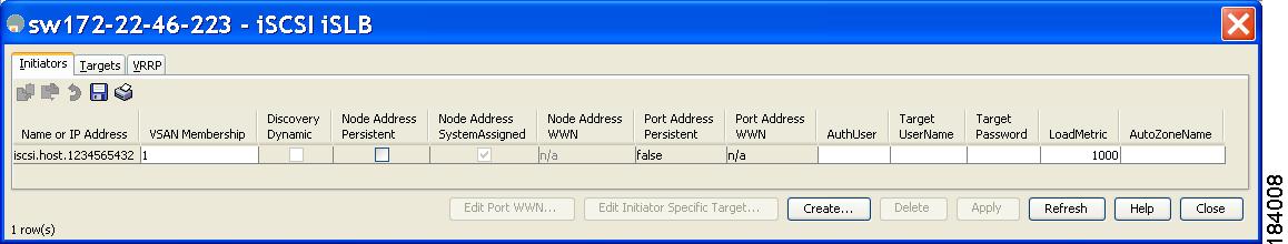
Step 2![]() Click Create to create a new iSCSI iSLB initiator.
Click Create to create a new iSCSI iSLB initiator.
You see the Create iSCSI iSLB Initiators dialog box (see Figure 4-33).
Figure 4-33 Create iSCSI iSLB Initiators Dialog Box
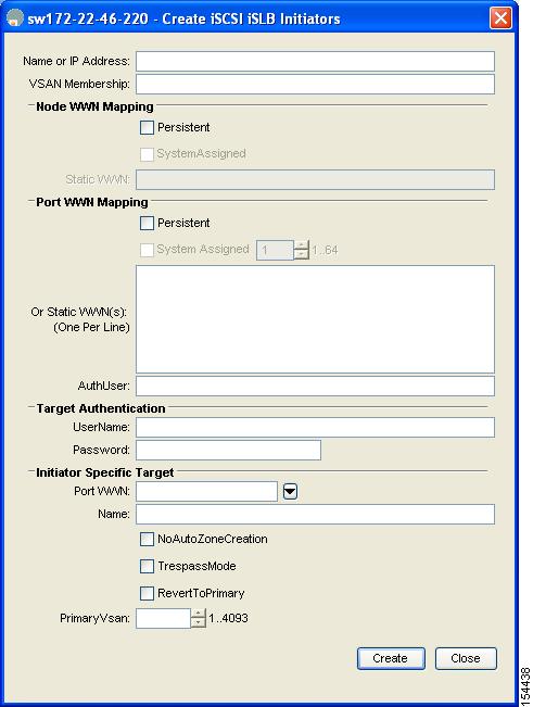
Step 3![]() Set the Name or IP Address field to the iSLB name or IP address.
Set the Name or IP Address field to the iSLB name or IP address.
Step 4![]() Set the VSAN Membership field to the VSAN that you want the iSLB initiator in.
Set the VSAN Membership field to the VSAN that you want the iSLB initiator in.
Also see the “Assigning VSAN Membership for iSLB Initiators” section.
Step 5![]() Check the Persistent check box to convert a dynamic nWWN to static for the iSLB initiator.
Check the Persistent check box to convert a dynamic nWWN to static for the iSLB initiator.
Also see the “Making the Dynamic iSLB Initiator WWN Mapping Static” section.
Step 6![]() (Optional) Check the SystemAssigned check box to have the switch assign the nWWN.
(Optional) Check the SystemAssigned check box to have the switch assign the nWWN.
Step 7![]() (Optional) Set the Static WWN field to manually assign the static nWWN. You must ensure uniqueness for this nWWN.
(Optional) Set the Static WWN field to manually assign the static nWWN. You must ensure uniqueness for this nWWN.
Step 8![]() (Optional) Check the Port WWN Mapping Persistent check box to convert dynamic pWWNs to static for the iSLB initiator.
(Optional) Check the Port WWN Mapping Persistent check box to convert dynamic pWWNs to static for the iSLB initiator.
See the “Making the Dynamic iSLB Initiator WWN Mapping Static” section.
Step 9![]() (Optional) Check the SystemAssigned check box and set the number of pWWNs you want to have the switch assign the PWWN.
(Optional) Check the SystemAssigned check box and set the number of pWWNs you want to have the switch assign the PWWN.
Step 10![]() (Optional) Set the Static WWN(s) field to manually assign the static pWWNs.
(Optional) Set the Static WWN(s) field to manually assign the static pWWNs.
You must ensure uniqueness for these pWWN.
Step 11![]() (Optional) Set the AuthUser field to the username that you want to restrict the iSLB initiator to for iSLB authentication.
(Optional) Set the AuthUser field to the username that you want to restrict the iSLB initiator to for iSLB authentication.
Also see the “Restricting iSLB Initiator Authentication” section.
Step 12![]() Fill in the Username and Password fields to configure iSLB initiator target CHAP authentication.
Fill in the Username and Password fields to configure iSLB initiator target CHAP authentication.
Also see the “Configuring iSLB Session Authentication” section.
Step 13![]() In the Initiator Specific Target section, set the pWWN to configure an iSLB initiator target.
In the Initiator Specific Target section, set the pWWN to configure an iSLB initiator target.
Step 14![]() (Optional) Set the Name field to a globally unique identifier (IQN).
(Optional) Set the Name field to a globally unique identifier (IQN).
Step 15![]() (Optional) Check the NoAutoZoneCreation check box to disable auto-zoning.
(Optional) Check the NoAutoZoneCreation check box to disable auto-zoning.
Step 16![]() (Optional) Check the TresspassMode check box.
(Optional) Check the TresspassMode check box.
Also see the “LUN Trespass for Storage Port Failover” section.
Step 17![]() (Optional) Check the RevertToPrimary check box to revert back to the primary port after an HA failover when the primary port comes back up.
(Optional) Check the RevertToPrimary check box to revert back to the primary port after an HA failover when the primary port comes back up.
Step 18![]() Set the PrimaryVsan to the VSAN for the iSLB initiator target.
Set the PrimaryVsan to the VSAN for the iSLB initiator target.
Step 19![]() Click Create to create this iSLB initiator.
Click Create to create this iSLB initiator.
Step 20![]() If CFS is enabled, select commit from the CFS drop-down menu.
If CFS is enabled, select commit from the CFS drop-down menu.
Configuring iSLB Initiators
This section includes the following topics:
- Configuring iSLB Initiator Names or IP Addresses
- Assigning WWNs to iSLB Initiators
- Making the Dynamic iSLB Initiator WWN Mapping Static
- Assigning VSAN Membership for iSLB Initiators
- Configuring Metrics for Load Balancing
- Verifying iSLB Initiator Configuration
- Verifying iSLB Authentication Configuration
- Configuring Load Balancing Using VRRP
- Configuring iSLB Session Authentication
- Verifying iSLB Authentication Configuration
Configuring iSLB Initiator Names or IP Addresses
You must specify the iSLB initiator name or IP address before configuring it.
Note![]() Specifying the iSLB initiator name or IP address is the same as for an iSCSI initiator. See the “Static Mapping” section.
Specifying the iSLB initiator name or IP address is the same as for an iSCSI initiator. See the “Static Mapping” section.
To enter iSLB initiator configuration submode using the name option for an iSLB initiator, follow these steps:
To enter iSLB initiator configuration submode using the ip-address option for an iSLB initiator, follow these steps:
Assigning WWNs to iSLB Initiators
An iSLB host is mapped to an N port’s WWNs by one of the following mechanisms:
Note![]() Assigning WWNs for iSLB initiators is the same as for iSCSI initiators. For information on dynamic and static mapping, see the “WWN Assignment for iSCSI Initiators” section.
Assigning WWNs for iSLB initiators is the same as for iSCSI initiators. For information on dynamic and static mapping, see the “WWN Assignment for iSCSI Initiators” section.
Tip![]() We recommend using the SystemAssign system-assign option. If you manually assign a WWN, you must ensure its uniqueness (see the Cisco Fabric Manager Fabric Configuration Guide and Cisco MDS 9000 Family NX-OS Fabric Configuration Guide for more information). You should not use any previously assigned WWNs.
We recommend using the SystemAssign system-assign option. If you manually assign a WWN, you must ensure its uniqueness (see the Cisco Fabric Manager Fabric Configuration Guide and Cisco MDS 9000 Family NX-OS Fabric Configuration Guide for more information). You should not use any previously assigned WWNs.
Making the Dynamic iSLB Initiator WWN Mapping Static
After a dynamic iSLB initiator has logged in, you may decide to permanently keep the automatically assigned nWWN/pWWN mapping to allow this initiator to use the same mapping the next time it logs in (see the “Dynamic Mapping” section).
You can convert a dynamic iSLB initiator to a static iSLB initiator and make its WWNs persistent
Note![]() You cannot convert a dynamic iSCSI initiator to a static iSLB initiator or a dynamic iSLB initiator to a static iSCSI initiator (see the “Dynamic Mapping” section on page 4-20).
You cannot convert a dynamic iSCSI initiator to a static iSLB initiator or a dynamic iSLB initiator to a static iSCSI initiator (see the “Dynamic Mapping” section on page 4-20).
Note![]() Making the dynamic mapping for iSLB initiators static is the same as for iSCSI. See the “Making the Dynamic iSLB Initiator WWN Mapping Static” section“Making the Dynamic iSCSI Initiator WWN Mapping Static” section.
Making the dynamic mapping for iSLB initiators static is the same as for iSCSI. See the “Making the Dynamic iSLB Initiator WWN Mapping Static” section“Making the Dynamic iSCSI Initiator WWN Mapping Static” section.
Note![]() Only statically mapped iSLB initiator configuration is distributed throughout the fabric using CFS. Dynamically and statically configured iSCSI initiator configurations are not distributed.
Only statically mapped iSLB initiator configuration is distributed throughout the fabric using CFS. Dynamically and statically configured iSCSI initiator configurations are not distributed.
See the Configuring iSLB Using Device Manager.
To permanently keep the automatically assigned nWWN/pWWN mapping, follow these steps:
Configuring iSLB Target Access Mapping
In iSLB, all fabric distributed configurations including iSCSI virtual target access are part of the iSCSI initiator configuration. Access is granted using the pWWN or the device alias. You can specify the one or more of the following optional parameters:
In addition, you can disable auto zoning.
If you configure an IQN for an initiator target then that name is used to identify the target. Otherwise, an unique IQN is generated for the initiator target.
To configure iSLB initiator access to an iSCSI virtual target, follow these steps:
To verify the iSLB target configuration, use the show islb initiator configured command.
Assigning VSAN Membership for iSLB Initiators
Individual iSLB hosts can be configured to be in a specific VSAN (similar to the DPVM feature for Fibre Channel. The specified VSAN overrides the iSCSI interface VSAN membership.
For more information, see the Cisco MDS 9000 Family NX-OS Fabric Manager Fabric Configuration Guide.
Note![]() Specifying the iSLB initiator VSAN is the same as for an iSCSI initiator. See the VSAN Membership for iSCSI.
Specifying the iSLB initiator VSAN is the same as for an iSCSI initiator. See the VSAN Membership for iSCSI.
To assign VSAN membership for iSLB initiators, follow these steps:
|
|
|
|
|---|---|---|
Configures an iSLB initiator using its IPv4 address and enters iSLB initiator configuration submode. |
||
Note![]() When an iSLB initiator is configured in any other VSAN (other than VSAN 1, the default VSAN), for example VSAN 2, the initiator is automatically removed from VSAN 1. If you also want it to be present in VSAN 1, you must explicitly configure the initiator in VSAN 1.
When an iSLB initiator is configured in any other VSAN (other than VSAN 1, the default VSAN), for example VSAN 2, the initiator is automatically removed from VSAN 1. If you also want it to be present in VSAN 1, you must explicitly configure the initiator in VSAN 1.
Configuring Metrics for Load Balancing
You can assign a load metric to each initiator for weighted load balancing. The load calculated is based on the number of initiators on a given iSCSI interface. This feature accommodates initiators with different bandwidth requirements. For example, you could assign a higher load metric to a database server than to a web server. Weighted load balancing also accommodates initiators with different link speeds.
Also, you can configure initiator targets using the device alias or the pWWN. If you configure an IQN for an initiator target, then that name is used to identify the initiator target. Otherwise, a unique IQN is generated for the initiator target.
For more information on load balancing, see the “Load Balancing Using VRRP” section.
Choose IP > iSCSI iSLB in Device Manager and set the LoadMetric field to change the load balancing metric for an iSLB initiator.
See the Configuring iSLB Using Device Manager.
To configure a weight for load balancing, follow these steps:
|
|
|
|
|---|---|---|
switch(config)# islb initiator name iqn.1987-02.com.cisco.initiator |
Configures an iSLB initiator using the name of the initiator node and enters iSLB initiator configuration mode. |
|
Verifying iSLB Initiator Configuration
To verify the iSLB initiator configuration, use the show islb initiator configured command.
Configuring iSLB Initiator Targets
You can configure initiator targets using the device alias or the pWWN. You can also optionally specify one or more of the following optional parameters:
Note![]() The VSAN identifier is optional if the target is online. If the target is not online, the VSAN identifier is required.
The VSAN identifier is optional if the target is online. If the target is not online, the VSAN identifier is required.
In addition, you can disable auto-zoning.
If you configure an IQN for an initiator target, then that name is used to identify the initiator target. Otherwise, a unique IQN is generated for the initiator target.
To configure iSLB initiator targets, follow these steps:
To configure additional iSLB initiator targets using Device Manager, follow these steps:
Step 1![]() Choose IP > iSCSI iSLB.
Choose IP > iSCSI iSLB.
You see the iSCSI iSLB dialog box (see Figure 4-32).
Step 2![]() Click on the initiator you want to add targets to and click Edit Initiator Specific Targets.
Click on the initiator you want to add targets to and click Edit Initiator Specific Targets.
You see the Initiator Specific Target dialog box.
Step 3![]() Click Create to create a new initiator target.
Click Create to create a new initiator target.
You see the Create Initiator Specific Target dialog box (see Figure 4-34).
Figure 4-34 Create Initiator Specific Target Dialog Box
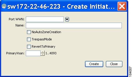
Step 4![]() Fill in the pWWN field with the initiator target pWWN.
Fill in the pWWN field with the initiator target pWWN.
Step 5![]() (Optional) Set the Name field to a globally unique identifier (IQN).
(Optional) Set the Name field to a globally unique identifier (IQN).
Step 6![]() (Optional) Check the NoAutoZoneCreation check box to disable auto-zoning (see Figure 4-33).
(Optional) Check the NoAutoZoneCreation check box to disable auto-zoning (see Figure 4-33).
Step 7![]() (Optional) Check the TresspassMode check box. See the “LUN Trespass for Storage Port Failover” section.
(Optional) Check the TresspassMode check box. See the “LUN Trespass for Storage Port Failover” section.
Step 8![]() (Optional) Check the RevertToPrimary check box to revert back to the primary port after an HA failover when the primary port comes back up.
(Optional) Check the RevertToPrimary check box to revert back to the primary port after an HA failover when the primary port comes back up.
Step 9![]() Set the PrimaryVsan to the VSAN for the iSLB initiator target.
Set the PrimaryVsan to the VSAN for the iSLB initiator target.
Step 10![]() Click Create to create this iSLB initiator target.
Click Create to create this iSLB initiator target.
Step 11![]() If CFS is enabled, select commit from the CFS drop-down menu.
If CFS is enabled, select commit from the CFS drop-down menu.
Configuring and Activating Zones for iSLB Initiators and Initiator Targets
You can configure a zone name where the iSLB initiators and initiator targets are added. If you do not specify a zone name, the IPS manager creates one dynamically. iSLB zone sets have the following considerations:
- Auto-zoning of the initiator with the initiator targets is enabled by default.
- A zone set must be active in a VSAN for auto-zones to be created in that VSAN.
- iSLB zone set activation might fail if another zone set activation is in process or if the zoning database is locked. Retry the iSLB zone set activation if a failure occurs. To avoid this problem, only perform only one zoning related operation (normal zones, IVR zones, or iSLB zones) at a time.
- Auto-zones are created when the zone set is activated and there has been at least one change in the zoneset. The activation has no effect if only the auto-zones have changed.
To configure the iSLB initiator optional auto-zone name and activate the zone set, follow these steps:
Choose IP > iSCSI iSLB in Device Manager and set the autoZoneName field to change the auto zone name for an iSLB initiator.
Verifying iSLB Zoning Configuration
The following example shows the show zoneset active command output when the dynamically generated zone name is used:
The following example shows the show zoneset active command output when the configured zone name IslbZone is used:
Configuring iSLB Session Authentication
The Fibre Channel module with IPS ports and MPS-14/2 module support the iSLB authentication mechanism to authenticate iSLB hosts that request access to storage. By default, the Fibre Channel module with IPS ports and MPS-14/2 module allow CHAP or None authentication of iSCSI initiators. If authentication is always used, you must configure the switch to allow only CHAP authentication.
For CHAP user name or secret validation you can use any method supported and allowed by the Cisco MDS AAA infrastructure (see the Cisco Fabric Manager Security Configuration GuideCisco MDS 9000 Family NX-OS Security Configuration Guide for more information). AAA authentication supports RADIUS, TACACS+, or a local authentication device.
Note![]() Specifying the iSLB session authentication is the same as for iSCSI. See the “iSCSI Session Authentication” section.
Specifying the iSLB session authentication is the same as for iSCSI. See the “iSCSI Session Authentication” section.
Restricting iSLB Initiator Authentication
By default, the iSLB initiator can use any user name in the RADIUS or local AAA database in authenticating itself to the Fibre Channel module with IPS ports or MPS-14/2 module (the CHAP user name is independent of the iSLB initiator name). The Fibre Channel module with IPS ports or MPS-14/2 module allows the initiator to log in as long as it provides a correct response to the CHAP challenge sent by the switch. This can be a problem if one CHAP user name and password have been compromised.
To restrict an initiator to use a specific user name for CHAP authentication, follow these steps:
Choose IP > iSCSI iSLB in Device Manager and set the AuthName field to restrict an initiator to use a specific user name for CHAP authentication.
Mutual CHAP Authentication
In addition to the Fibre Channel module with IPS ports and MPS-14/2 module authentication of the iSLB initiator, the Fibre Channel module with IPS ports and MPS-14/2 module also support a mechanism for the iSLB initiator to authenticate the Cisco MDS switch’s initiator target during the iSCSI login phase. This authentication requires the user to configure a user name and password for the switch to present to the iSLB initiator. The provided password is used to calculate a CHAP response to a CHAP challenge sent to the IPS port by the initiator.
To configure a per-initiator user name and password used by the switch to authenticate itself to an initiator, follow these steps:
Choose IP > iSCSI iSLB in Device Manager and set the Target Username and Target Password fields to configure a per-initiator user name and password used by the switch to authenticate itself to an initiator.
Verifying iSLB Authentication Configuration
Use the show running-config and the show iscsi global (see Example 4-6) commands to display the global configuration. Use the show running-config and the show islb initiator configured (see Example 4-14) commands to display the initiator specific configuration.
To verify the iSLB user name and mutual CHAP configuration, use the show islb initiator configured command:
Load Balancing Using VRRP
You can configure Virtual Router Redundancy Protocol (VRRP) load balancing for iSLB. The host is configured with a VRRP address as the portal address. When the VRRP master port receives the first iSCSI session from an initiator, it assigns a backup port to serve that particular host. The information is synchronized to all switches through CFS if recovery is needed when a master port fails. The initiator gets a temporary redirect iSCSI login response. The host then logs in to the backup port at its physical IP address. All iSCSI interfaces in a VRRP group that has load balancing enabled must have the same interface VSAN, authentication, proxy initiator mode, and forwarding mode.
You can configure Virtual Router Redundancy Protocol (VRRP) load balancing for iSLB. Figure 4-35 shows an example of load balancing using iSLB.
Figure 4-35 iSLB Initiator Load Balancing Example
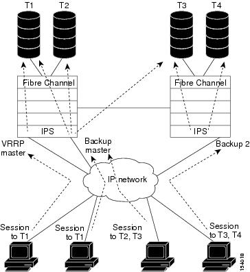
The host is configured with a VRRP address as the portal address. When the VRRP master port receives the first iSCSI session from an initiator, it assigns a backup port to serve that particular host. This information is synchronized to all switches through CFS if recovery is needed when a master port fails. The initiator gets a temporary redirect iSCSI login response. The host then logs in to the backup port at its physical IP address. If the backup port goes down, the host will revert to the master port. The master port knows through CFS that the backup port has gone down and redirects the host to another backup port.
Note![]() If an Ethernet port channel is configured between the Fibre Channel module with IPS ports and an Ethernet switch, the load balancing policy on the Ethernet switch must be based on source/destination IP address only, not port numbers, for load balancing with VRRP to operate correctly.
If an Ethernet port channel is configured between the Fibre Channel module with IPS ports and an Ethernet switch, the load balancing policy on the Ethernet switch must be based on source/destination IP address only, not port numbers, for load balancing with VRRP to operate correctly.
Note![]() An initiator can also be redirected to the physical IP address of the master interface.
An initiator can also be redirected to the physical IP address of the master interface.
Tip![]() iSLB VRRP load balancing is based on the number of iSLB initiators and not number of sessions. Any iSLB initiator that has more targets configured than the other iSLB initiators (resulting in more sessions) should be configured with a higher load metric. For example, you can increase the load metric of the iSLB initiator with more targets to 3000 from the default value of 1000.
iSLB VRRP load balancing is based on the number of iSLB initiators and not number of sessions. Any iSLB initiator that has more targets configured than the other iSLB initiators (resulting in more sessions) should be configured with a higher load metric. For example, you can increase the load metric of the iSLB initiator with more targets to 3000 from the default value of 1000.
Changing iSCSI Interface Parameters and the Impact on Load Balancing
All iSCSI interfaces in a VRRP group that has load balancing enabled must have the same interface VSAN, authentication, proxy initiator mode, and forwarding mode. When you need to change any of these parameters for the iSCSI interfaces in a VRRP group, you must do so one interface at a time. During the transition time when the parameter is changed on some interfaces in the VRRP group and not the others, the master port does not redirect new initiators and instead handles them locally.
VRRP Load Balancing Algorithm for Selecting Gigabit Ethernet Interfaces
When the VRRP master receives an iSCSI session request from an initiator, it first checks for an existing mapping to one of the interfaces in that VRRP group. If such a mapping exists, the VRRP master redirects the initiator to that interface. If no such mapping exists, the VRRP master selects the least loaded interface and updates the selected interface’s load with the initiator’s iSLB metric (weight).
Note![]() The VRRP master interface is treated specially and it needs to take a lower load compared to the other interfaces. This is to account for the redirection work performed by the master interface for every session. A new initiator is assigned to the master interface only if the following is true for every other interface:
The VRRP master interface is treated specially and it needs to take a lower load compared to the other interfaces. This is to account for the redirection work performed by the master interface for every session. A new initiator is assigned to the master interface only if the following is true for every other interface:
VRRP backup interface load > [2 * VRRP master interface load + 1]
Example 4-17 and Example 4-18 are based on the following configurations:
- GigabitEthernet2/1.441 is the VRRP master interface for Switch1.
- GigabitEthernet2/2.441 is the VRRP backup interface for Switch1.
- GigabitEthernet1/1.441 is the VRRP backup interface for Switch2.
- GigabitEthernet1/2.441 is the VRRP backup interface for Switch2.
Example 4-17 Load Distribution with the Default Metric
The follow example output shows the initial load distribution for three initiators with the default load metric value:
The following example output shows load distribution for four initiators. The interface load metric value for the master interface changed from 0 to 1000.
The following example output shows load distribution for nine initiators. The interface load metric values for the backup interfaces have changed.
Example 4-18 Load Distribution with the Metric Set to 3000 on One Initiator
The following example output shows the initial load distribution for three initiators with one initiator having load metric of 3000 and the remaining initiator with the default metric value:
The follow example output shows load distribution for four initiators. The interface load metric value for the master interface changed from 0 to 1000.
The following example output shows load distribution for nine initiators. The interface load metric values for the backup interfaces have changed.
Configuring Load Balancing Using VRRP
You must first configure VRRP on the Gigabit Ethernet interfaces on the switch that connect to the IP network before configuring VRRP for iSLB. For information on how to configure VRRP on a Gigabit Ethernet interface, see the “Virtual Router Redundancy Protocol” section.
To configure VRRP load balancing using Device Manager, follow these steps:
Step 1![]() Choose IP > iSCSI iSLB.
Choose IP > iSCSI iSLB.
You see the iSCSI iSLB dialog box (see Figure 4-32).
Step 3![]() Click Create to configure VRRP load balancing for iSLB initiators.
Click Create to configure VRRP load balancing for iSLB initiators.
You see the Create iSCSI iSLB VRRP dialog box (see Figure 4-36).
Figure 4-36 Create iSCSI iSLB VRRP Dialog Box
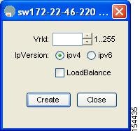
Step 4![]() Set the Vrld to the VRRP group number.
Set the Vrld to the VRRP group number.
Step 5![]() Select either ipv4 or ipv6 and check the LoadBalance check box.
Select either ipv4 or ipv6 and check the LoadBalance check box.
Step 6![]() Click Create to enable load balancing.
Click Create to enable load balancing.
Step 7![]() If CFS is enabled, select commit from the CFS drop-down menu.
If CFS is enabled, select commit from the CFS drop-down menu.
Enabling VRRP for Load Balancing
To enable or disable VRRP for iSLB, follow these steps:
|
|
|
|
|---|---|---|
Verifying iSLB VRRP Load Balancing Configuration
To verify the iSLB VRRP load balancing configuration for IPv4, use the show vrrp vr command:
To verify the iSLB VRRP load balancing configuration for IPv6, use the show vrrp ipv6 vr command:
Displaying iSLB VRRP Information
Use the show islb vrrp summary vr command to display VRRP load-balancing information:
iSLB Configuration Distribution Using CFS
You can distribute the configuration for iSLB initiators and initiator targets on an MDS switch. This feature lets you synchronize the iSLB configuration across the fabric from the console of a single MDS switch. The iSCSI initiator idle timeout, global authentication, and iSCSI dynamic initiator mode parameters are also distributed. CFS distribution is disabled by default.
Configuration for iSLB initiators and initiator targets on an MDS switch can be distributed using the Cisco Fabric Services (CFS). This feature allows you to synchronize the iSLB configuration across the fabric from the console of a single MDS switch. The iSCSI initiator idle timeout, iSCSI dynamic initiator mode, and global authentication parameters are also distributed. CFS distribution is disabled by default (see the Cisco Fabric Manager System Management Configuration Guide and Cisco MDS 9000 Family NX-OS System Management Configuration Guide for more information).
After enabling the distribution, the first configuration starts an implicit session. All server configuration changes entered thereafter are stored in a temporary database and applied to all switches in the fabric (including the originating one) when you explicitly commit the database.
When CFS is enabled for iSLB, the first iSLB configuration operation starts a CFS session and locks the iSLB configuration in the fabric. The configuration changes are applied to the pending configuration database. When you make the changes to the fabric, the pending configuration is distributed to all the switches in the fabric. Each switch then validates the configuration. This check ensures the following:
- The VSANs assigned to the iSLB initiators are configured on all the switches.
- The static WWNs configured for the iSLB initiators are unique and available on all the switches.
- The iSLB initiator node names do not conflict with the iSCSI initiators on all the switches.
After the check completes successfully, all the switches commit the pending configuration to the running configuration. If any check fails, the entire commit fails.
Note![]() iSLB is only fully supported when CFS is enabled. Using iSLB auto-zoning without enabling CFS mode may cause traffic disruption when any zone set is activated.
iSLB is only fully supported when CFS is enabled. Using iSLB auto-zoning without enabling CFS mode may cause traffic disruption when any zone set is activated.
Note![]() CFS does not distribute non-iSLB initiator configurations or import Fibre Channel target settings.
CFS does not distribute non-iSLB initiator configurations or import Fibre Channel target settings.
Non-iSLB virtual targets will continue to support advertised interfaces option.
Tip![]() The pending changes are only available in the volatile directory and are discarded if the switch is restarted.
The pending changes are only available in the volatile directory and are discarded if the switch is restarted.
Distributing iSLB Configuration Using CFS
This section contains the following:
- Enabling iSLB Configuration Distribution
- Locking the Fabric
- Committing Changes to the Fabric
- Discarding Pending Changes
- Clearing a Fabric Lock
- CFS Merge Process
- Displaying Pending iSLB Configuration Changes
- Displaying iSLB CFS Status
- Displaying iSLB CFS Distribution Session Status
- Displaying iSLB CFS Merge Status
- iSLB CFS Merge Status Conflicts
Enabling iSLB Configuration Distribution
To enable CFS distribution of the iSLB configuration, follow these steps:
|
|
|
|
|---|---|---|
To enable CFS distribution of the iSLB configuration using Device Manager, follow these steps:
You see the CFS dialog box (see Figure 4-37).
Figure 4-37 Enabling CFS in Device Manager
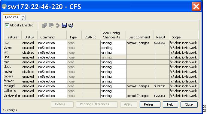
Step 2![]() Set the Command field to enable for the iSLB feature.
Set the Command field to enable for the iSLB feature.
Step 3![]() Click Apply to save this change.
Click Apply to save this change.
Locking the Fabric
The first action that modifies the existing configuration creates the pending configuration and locks the feature in the fabric. Once you lock the fabric, the following conditions apply:
- No other user can make any configuration changes to this feature.
- A pending configuration is created by copying the active configuration. Modifications from this point on are made to the pending configuration and remain there until you commit the changes to the active configuration (and other switches in the fabric) or discard them.
Note![]() iSCSI configuration changes are not allowed when an iSLB CFS session is active.
iSCSI configuration changes are not allowed when an iSLB CFS session is active.
Committing Changes to the Fabric
To apply the pending iSLB configuration changes to the active configuration and to other MDS switches in the fabric, you must commit the changes. The pending configuration changes are distributed and, on a successful commit, the configuration changes are applied to the active configuration in the MDS switches throughout the fabric, the automatic zones are activated, and the fabric lock is released.
To commit iSLB configuration changes to other MDS switches in the fabric, activate iSLB automatic zones, and release the fabric lock, follow these steps:
|
|
|
|
|---|---|---|
Commits the iSLB configuration distribution, activates iSLB automatic zones, and releases the fabric lock. |
To commit iSLB configuration changes to other MDS switches in the fabric, activate iSLB automatic zones, and release the fabric lock using Device Manager, follow these steps:
You see the CFS Configuration dialog box (see Figure 4-37).
Step 2![]() Set the Command field to commit for the iSLB feature.
Set the Command field to commit for the iSLB feature.
Step 3![]() Click Apply to save this change.
Click Apply to save this change.
Discarding Pending Changes
At any time, you can discard the pending changes to the iSLB configuration and release the fabric lock. This action has no affect on the active configuration on any switch in the fabric.
To discard the pending iSLB configuration changes and release the fabric lock, follow these steps:
|
|
|
|
|---|---|---|
To discard the pending iSLB configuration changes and release the fabric lock using Device Manager, follow these steps:
You see the CFS Configuration dialog box (see Figure 4-37).
Step 2![]() Set the Command field to abort for the iSLB feature.
Set the Command field to abort for the iSLB feature.
Step 3![]() Click Apply to save this change.
Click Apply to save this change.
Clearing a Fabric Lock
If you have performed an iSLB configuration task and have not released the lock by either committing or discarding the changes, an administrator can release the lock from any switch in the fabric. If the administrator performs this task, your pending changes are discarded and the fabric lock is released.
Note![]() The pending changes are only available in the volatile directory and are discarded if the switch is restarted.
The pending changes are only available in the volatile directory and are discarded if the switch is restarted.
To release a fabric lock, issue the clear islb session command in EXEC mode using a login ID that has administrative privileges:
To release a fabric lock using Device Manager, follow these steps:
You see the CFS Configuration dialog box (see Figure 4-37).
Step 2![]() Set the Command field to clear for the iSLB feature.
Set the Command field to clear for the iSLB feature.
Step 3![]() Click Apply to save this change.
Click Apply to save this change.
CFS Merge Process
When two fabrics merge, CFS attempts to merge the iSLB configuration from both the fabrics. A designated switch (called the dominant switch) in one fabric sends its iSLB configuration to a designated switch (called the subordinate switch) in the other fabric. The subordinate switch compares its running configuration to the received configuration for any conflicts. If no conflicts are detected, it merges the two configurations and sends it to all the switches in both the fabrics. Each switch then validates the configuration. This check ensures the following:
- VSANs assigned to the iSLB initiators are configured on all the switches.
- The static WWNs configured for the iSLB initiators are unique and available on all the switches.
- The iSLB initiator node names have no conflicts with iSCSI initiators on all the switches.
If this check completes successfully, the subordinate switch directs all the switches to commit the merged configuration to running configuration. If any check fails, the merge fails.
The show islb merge status command displays the exact reason for the failure. The first successful commit request after a merge failure takes the fabric out of the merge failure state.
Displaying Pending iSLB Configuration Changes
You can display the pending configuration changes using the show islb pending command:
You can display the differences between the pending configuration and the current configuration using the show islb pending-diff command:
Displaying iSLB CFS Status
You can display the iSLB CFS status using the show islb session status command:
Displaying iSLB CFS Distribution Session Status
You can display the status of the iSLB CFS distribution session using the show islb cfs-session status command:
Displaying iSLB CFS Merge Status
You can display the iSLB CFS merge status using the show islb merge status command:
iSLB CFS Merge Status Conflicts
Merge conflicts may occur. User intervention is required for the following merge conflicts:
- The iSCSI global authentication or iSCSI initiator idle timeout parameters are not configured the same in the two fabrics.
- The same iSLB initiator is configured differently in the two fabrics.
- An iSLB initiator in one fabric has the same name as an iSCSI initiator in the other fabric.
- Duplicate pWWN/nWWN configuration is detected in the two fabric. For example, a pWWN/nWWN configured for an iSLB initiator on one fabric is configured for an iSCSI initiator or a different iSLB initiator in the other fabric.
- A VSAN configured for an iSLB initiator in one fabric does not exist in the other fabric.
Tip![]() Check the syslog for details on merge conflicts.
Check the syslog for details on merge conflicts.
User intervention is not required when the same iSLB initiator has a different set of non-conflicting initiator targets. The merged configuration is the union of all the initiator targets.
iSCSI High Availability
The following high availability features are available for iSCSI configurations:
Transparent Target Failover
The following high-availability features are available for iSCSI configurations:
- iSCSI high availability with host running multi-path software—In this topology, you have recovery from failure of any of the components. The host multi-path software takes care of load balancing or failover across the different paths to access the storage.
- iSCSI high availability with host not having multi-path software—Without multi-path software, the host does not have knowledge of the multiple paths to the same storage.
iSCSI High Availability with Host Running Multipath Software
Figure 4-38 shows the physical and logical topology for an iSCSI HA solution for hosts running multi-path software. In this scenario, the host has four iSCSI sessions. There are two iSCSI sessions from each host NIC to the two IPS ports.
Figure 4-38 Host Running Multipath Software
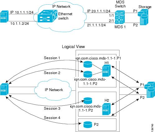
Each IPS ports is exporting the same two Fibre Channel target ports of the storage but as different iSCSI target names if you use dynamic iSCSI targets). So the two IPS ports are exporting a total of four iSCSI target devices. These four iSCSI targets map the same two ports of the Fibre Channel target.
The iSCSI host uses NIC-1 to connect to IPS port 1 and NIC-2 to connect to IPS port 2. Each IPS port exports two iSCSI targets, so the iSCSI host creates four iSCSI sessions.
If the iSCSI host NIC-1 fails (see Figure 4-38 for the physical view), then sessions 1 and 2 fail but we still have sessions 3 and 4.
If the IPS port 1 fails, the iSCSI host cannot connect to the IPS port, and sessions 1 and 2 fail. But sessions 3 and 4 are still available.
If the storage port 1 fails, then the IPS ports will terminate sessions 1 and 3 (put iSCSI virtual target iqn.com.cisco.mds-5.1-2.p1 and iqn-com.cisco.mds-5.1-1.p1 in offline state). But sessions 2 and 4 are still available.
In this topology, you have recovery from failure of any of the components. The host multi-path software takes care of load-balancing or failover across the different paths to access the storage.
iSCSI HA with Host Not Having Any Multipath Software
The above topology will not work if the host does not have multi-path software because the host has multiple sessions to the same storage. Without multi-path software the host does not have knowledge of the multiple paths to the same storage.
IP storage has two additional features that provide an HA solution in this scenario.
- IPS ports support the VRRP feature (see “Configuring VRRP for IPStorage Interfaces” section) to provide failover for IPS ports.
- IPS has transparent Fibre Channel target failover for iSCSI static virtual targets.
Statically imported iSCSI targets have an additional option to provide a secondary pWWN for the Fibre Channel target. This can be used when the physical Fibre Channel target is configured to have an LU visible across redundant ports. When the active port fails, the secondary port becomes active and the iSCSI session switches to use the new active port (see Figure 4-39).
Figure 4-39 Static Target Importing Through Two Fibre Channel Ports
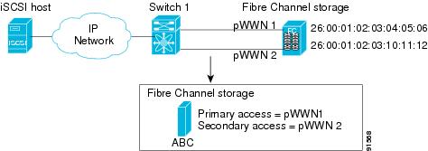
In Figure 4-39, you can create an iSCSI virtual target that is mapped to both pWWN1 and pWWN2 to provide redundant access to the Fibre Channel targets.
The failover to a secondary port is done transparently by the IPS port without impacting the iSCSI session from the host. All outstanding I/Os are terminated with a check condition status when the primary port fails. New I/Os received during the failover are not completed and receive a busy status.
Tip![]() If you use LUN mapping, you can define a different secondary Fibre Channel LUN if the LU number is different.
If you use LUN mapping, you can define a different secondary Fibre Channel LUN if the LU number is different.
Enable the optional revert-primary-port option to direct the IPS port to switch back to the primary port when the primary port is up again. If this option is disabled (default) and the primary port is up again after a switchover, the old sessions will remain with the secondary port and do not switch back to the primary port. However, any new session will use the primary port. This is the only situation when both the primary and secondary ports are used at the same time.
To create a static iSCSI virtual target, follow these steps:
To create a static iSCSI virtual target for the entire Fibre Channel target port using Device Manager, follow these steps:
You see the iSCSI configuration (see Figure 4-12).
Step 2![]() Click the Targets tab to display a list of existing iSCSI targets shown (see Figure 4-13).
Click the Targets tab to display a list of existing iSCSI targets shown (see Figure 4-13).
Step 3![]() Click Create to create an iSCSI target.
Click Create to create an iSCSI target.
You see the Create iSCSI Targets dialog box (see Figure 4-15).
Step 4![]() Set the iSCSI target node name in the iSCSI Name field, in IQN format.
Set the iSCSI target node name in the iSCSI Name field, in IQN format.
Step 5![]() Set the Port WWN field for the Fibre Channel target port you are mapping.
Set the Port WWN field for the Fibre Channel target port you are mapping.
Step 6![]() Click the Select from List radio button and set the iSCSI initiator node names or IP addresses that you want this virtual iSCSI target to access, or click the All radio button to let the iSCSI target access all iSCSI initiators. See the “iSCSI Access Control” section.
Click the Select from List radio button and set the iSCSI initiator node names or IP addresses that you want this virtual iSCSI target to access, or click the All radio button to let the iSCSI target access all iSCSI initiators. See the “iSCSI Access Control” section.
Step 7![]() Chick the Select from List radio button and check each interface you want to advertise the iSCSI targets on or choose the All radio button to advertise all interfaces.
Chick the Select from List radio button and check each interface you want to advertise the iSCSI targets on or choose the All radio button to advertise all interfaces.
Step 8![]() Click Apply to save this change.
Click Apply to save this change.
LUN Trespass for Storage Port Failover
In addition to the high availability of statically imported iSCSI targets, the trespass feature is available to enable the move of LUs, on an active port failure, from the active to the passive port of a statically imported iSCSI target.
In physical Fibre Channel targets, which are configured to have LUs visible over two Fibre Channel N ports, when the active port fails, the passive port takes over. Some physical Fibre Channel targets require that the trespass feature be used to move the LUs from the active port to the passive port. A statically imported iSCSI target's secondary pWWN option and an additional option of enabling the trespass feature is available for a physical Fibre Channel target with redundant ports. When the active port fails, the passive port becomes active, and if the trespass feature is enabled, the Cisco MDS switch sends a request to the target to move the LUs on the new active port. The iSCSI session switches to use the new active port and the moved LUs are accessed over the new active port (see Figure 4-40).
Figure 4-40 Virtual Target with an Active Primary Port
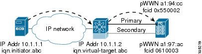
To enable the trespass feature for a static iSCSI virtual target, follow these steps:
Use the show iscsi virtual-target command to verify:
In Device Manager, choose IP > iSCSI, select the Targets tab, and check the Trespass Mode check box to enable the trespass feature for a static iSCSI virtual target.
Multiple IPS Ports Connected to the Same IP Network
Figure 4-41 provides an example of a configuration with multiple Gigabit Ethernet interfaces in the same IP network.
Figure 4-41 Multiple Gigabit Ethernet Interfaces in the Same IP Network
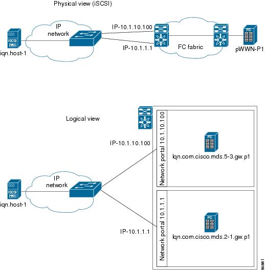
In Figure 4-41, each iSCSI host discovers two iSCSI targets for every physical Fibre Channel target (with different names). The multi-pathing software on the host provides load-balancing over both paths. If one Gigabit Ethernet interface fails, the host multi-pathing software is not affected because it can use the second path.
VRRP-Based High Availability
Figure 4-42 provides an example of a VRRP-based high availability iSCSI configuration.
Figure 4-42 VRRP-Based iSCSI High Availability
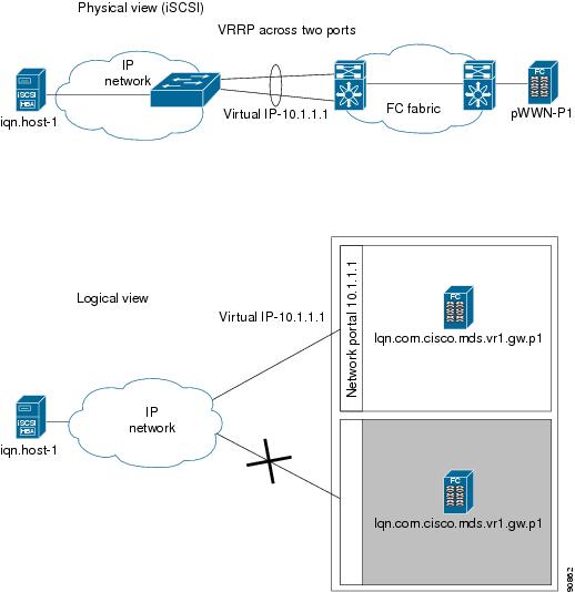
In Figure 4-42, each iSCSI host discovers one iSCSI target for every physical Fibre Channel target. When the Gigabit Ethernet interface of the VRRP master fails, the iSCSI session is terminated. The host then reconnects to the target and the session comes up because the second Gigabit Ethernet interface has taken over the virtual IP address as the new master.
Ethernet Port Channel-Based High Availability
Note![]() All iSCSI data traffic for one iSCSI link is carried on one TCP connection. Consequently, the aggregated bandwidth is 1 Gbps for that iSCSI link.
All iSCSI data traffic for one iSCSI link is carried on one TCP connection. Consequently, the aggregated bandwidth is 1 Gbps for that iSCSI link.
Figure 4-43 provides a sample Ethernet Port Channel-based high availability iSCSI configuration.
Figure 4-43 Ethernet Port Channel-Based iSCSI High Availability
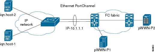
In Figure 4-43, each iSCSI host discovers one iSCSI target for every physical Fibre Channel target. The iSCSI session from the iSCSI host to the iSCSI virtual target (on the IPS port) uses one of the two physical interfaces (because an iSCSI session uses one TCP connection). When the Gigabit Ethernet interface fails, the Fibre Channel module with IPS ports and the Ethernet switch transparently forwards all the frames on to the second Gigabit Ethernet interface.
Note![]() If an Ethernet port channel is configured between the Fibre Channel module with IPS ports and an Ethernet switch, the load balancing policy on the Ethernet switch must be based on source/destination IP address only, not port numbers, for load balancing with VRRP to operate correctly.
If an Ethernet port channel is configured between the Fibre Channel module with IPS ports and an Ethernet switch, the load balancing policy on the Ethernet switch must be based on source/destination IP address only, not port numbers, for load balancing with VRRP to operate correctly.
iSCSI Authentication Setup Guidelines and Scenarios
This section provides guidelines on iSCSI authentication possibilities, setup requirements, and sample scenarios. It includes the following authentication setup guidelines:
- Configuring No Authentication
- Configuring CHAP with Local Password Database
- Configuring CHAP with External RADIUS Server
- iSCSI Transparent Mode Initiator
- Target Storage Device Requiring LUN Mapping
Note![]() This section does not specify the steps to enter or exit EXEC mode, configuration mode, or any submode. Be sure to verify the prompt before entering any command.
This section does not specify the steps to enter or exit EXEC mode, configuration mode, or any submode. Be sure to verify the prompt before entering any command.
Configuring No Authentication
Set the iSCSI authentication method to none to configure a network with no authentication:
In Fabric Manager, choose End Devices > iSCSI in the Physical Attributes pane. Then select the Globals tab and set the AuthMethod drop-down menu to none and click Apply Changes.
Configuring CHAP with Local Password Database
To configure authentication using the CHAP option with the local password database, follow these steps:
Step 1![]() Set the AAA authentication to use the local password database for the iSCSI protocol:
Set the AAA authentication to use the local password database for the iSCSI protocol:
Step 2![]() Set the iSCSI authentication method to require CHAP for all iSCSI clients:
Set the iSCSI authentication method to require CHAP for all iSCSI clients:
Step 3![]() Configure the user names and passwords for iSCSI users:
Configure the user names and passwords for iSCSI users:
Note![]() If you do not specify the iscsi option, the user name is assumed to be a Cisco MDS switch user instead of an iSCSI user.
If you do not specify the iscsi option, the user name is assumed to be a Cisco MDS switch user instead of an iSCSI user.
Step 4![]() Verify the global iSCSI authentication setup:
Verify the global iSCSI authentication setup:
To configure authentication using the CHAP option with the local password database, follow these steps:
Step 1![]() Set the AAA authentication to use the local password database for the iSCSI protocol:
Set the AAA authentication to use the local password database for the iSCSI protocol:
a.![]() In Fabric Manager, choose Switches > Security > AAA in the Physical Attributes pane.
In Fabric Manager, choose Switches > Security > AAA in the Physical Attributes pane.
b.![]() Click the Applications tab in the Information pane.
Click the Applications tab in the Information pane.
c.![]() Check the Local check box for the iSCSI row and click Apply Changes
Check the Local check box for the iSCSI row and click Apply Changes
Step 2![]() Set the iSCSI authentication method to require CHAP for all iSCSI clients:
Set the iSCSI authentication method to require CHAP for all iSCSI clients:
a.![]() In Fabric Manager, choose End Devices > iSCSI in the Physical Attributes pane.
In Fabric Manager, choose End Devices > iSCSI in the Physical Attributes pane.
b.![]() Click the Globals tab in the Information pane.
Click the Globals tab in the Information pane.
c.![]() Set the AuthMethod drop-down menu to chap and click Apply Changes.
Set the AuthMethod drop-down menu to chap and click Apply Changes.
Configuring CHAP with External RADIUS Server
To configure authentication using the CHAP option with an external RADIUS server, follow these steps:
Step 1![]() Configure the password for the Cisco MDS switch as RADIUS client to the RADIUS server:
Configure the password for the Cisco MDS switch as RADIUS client to the RADIUS server:
Step 2![]() Configure the RADIUS server IP address by performing one of the following:
Configure the RADIUS server IP address by performing one of the following:
Step 3![]() Configure the RADIUS server group IP address by performing one of the following:
Configure the RADIUS server group IP address by performing one of the following:
Step 4![]() Set up the iSCSI authentication method to require CHAP for all iSCSI clients:
Set up the iSCSI authentication method to require CHAP for all iSCSI clients:
Step 5![]() Verify that the global iSCSI authentication setup is for CHAP:
Verify that the global iSCSI authentication setup is for CHAP:
Step 6![]() Verify that the AAA authentication information is for iSCSI”
Verify that the AAA authentication information is for iSCSI”
Step 1![]() Configure the password for the Cisco MDS switch as RADIUS client to the RADIUS server:
Configure the password for the Cisco MDS switch as RADIUS client to the RADIUS server:
a.![]() In Fabric Manager, choose Switches > Security > AAA > RADIUS in the Physical Attributes pane.
In Fabric Manager, choose Switches > Security > AAA > RADIUS in the Physical Attributes pane.
b.![]() Click the Default tab in the Information pane.
Click the Default tab in the Information pane.
c.![]() Set the AuthKey field to the default password and click the Apply Changes icon.
Set the AuthKey field to the default password and click the Apply Changes icon.
Step 2![]() Configure the RADIUS server IP address:
Configure the RADIUS server IP address:
a.![]() In Fabric Manager, choose Switches > Security > AAA > RADIUS in the Physical Attributes pane.
In Fabric Manager, choose Switches > Security > AAA > RADIUS in the Physical Attributes pane.
b.![]() Click the Server tab in the Information pane and click Create Row.
Click the Server tab in the Information pane and click Create Row.
c.![]() Set the Index field to a unique number.
Set the Index field to a unique number.
d.![]() Set the IP Type radio button to ipv4 or ipv6.
Set the IP Type radio button to ipv4 or ipv6.
e.![]() Set the Name or IP Address field to the IP address of the RADIUS server and click Create.
Set the Name or IP Address field to the IP address of the RADIUS server and click Create.
Step 3![]() Create a RADIUS server group and add the RADIUS server to the group:
Create a RADIUS server group and add the RADIUS server to the group:
a.![]() In Fabric Manager, choose Switches > Security > AAA in the Physical Attributes pane.
In Fabric Manager, choose Switches > Security > AAA in the Physical Attributes pane.
b.![]() Select the Server Groups tab in the Information pane and click Create Row.
Select the Server Groups tab in the Information pane and click Create Row.
c.![]() Set the Index field to a unique number.
Set the Index field to a unique number.
d.![]() Set the Protocol radio button to radius.
Set the Protocol radio button to radius.
e.![]() Set the Name field to the server group name.
Set the Name field to the server group name.
f.![]() Set the ServerIDList to the index value of the RADIUS server (as created in Step 2 c.) and click Create.
Set the ServerIDList to the index value of the RADIUS server (as created in Step 2 c.) and click Create.
Step 4![]() Set up the authentication verification for the iSCSI protocol to go to the RADIUS server.
Set up the authentication verification for the iSCSI protocol to go to the RADIUS server.
a.![]() In Fabric Manager, choose Switches > Security > AAA in the Physical Attributes pane.
In Fabric Manager, choose Switches > Security > AAA in the Physical Attributes pane.
b.![]() Click the Applications tab in the Information pane.
Click the Applications tab in the Information pane.
c.![]() Right-click on the iSCSI row in the Type, SubType, Function column.
Right-click on the iSCSI row in the Type, SubType, Function column.
d.![]() Set the ServerGroup IDList to the index value of the Server Group (as created in Step 3 c) and click Create.
Set the ServerGroup IDList to the index value of the Server Group (as created in Step 3 c) and click Create.
Step 5![]() Set up the iSCSI authentication method to require CHAP for all iSCSI clients.
Set up the iSCSI authentication method to require CHAP for all iSCSI clients.
a.![]() In Fabric Manager, choose End Devices > iSCSI in the Physical Attributes pane.
In Fabric Manager, choose End Devices > iSCSI in the Physical Attributes pane.
b.![]() Select chap from the AuthMethod drop-down menu.
Select chap from the AuthMethod drop-down menu.
c.![]() Click the Apply Changes icon.
Click the Apply Changes icon.
Step 6![]() In Fabric Manager, choose End Devices > iSCSI in the Physical Attributes pane.
In Fabric Manager, choose End Devices > iSCSI in the Physical Attributes pane.
Step 7![]() Click the Globals tab in the Information pane to verify that the global iSCSI authentication setup is for CHAP.
Click the Globals tab in the Information pane to verify that the global iSCSI authentication setup is for CHAP.
Step 8![]() In Fabric Manager, choose Switches > Security > AAA in the Physical Attributes pane.
In Fabric Manager, choose Switches > Security > AAA in the Physical Attributes pane.
Step 9![]() Click the Applications tab in the Information pane to verify the AAA authentication information for iSCSI.
Click the Applications tab in the Information pane to verify the AAA authentication information for iSCSI.
To configure an iSCSI RADIUS server, follow these steps:
Step 1![]() Configure the RADIUS server to allow access from the Cisco MDS switch's management Ethernet IP address.
Configure the RADIUS server to allow access from the Cisco MDS switch's management Ethernet IP address.
Step 2![]() Configure the shared secret for the RADIUS server to authenticate the Cisco MDS switch.
Configure the shared secret for the RADIUS server to authenticate the Cisco MDS switch.
Step 3![]() Configure the iSCSI users and passwords on the RADIUS server.
Configure the iSCSI users and passwords on the RADIUS server.
iSCSI Transparent Mode Initiator
This scenario assumes the following configuration (see Figure 4-44):
- No LUN mapping or LUN masking or any other access control for hosts on the target device
- No iSCSI login authentication (that is, login authentication set to none)
- The topology is as follows:
–![]() iSCSI interface 7/1 is configured to identify initiators by IP address.
iSCSI interface 7/1 is configured to identify initiators by IP address.
–![]() iSCSI interface 7/5 is configured to identify initiators by node name.
iSCSI interface 7/5 is configured to identify initiators by node name.
–![]() The iSCSI initiator host 1 with IPv4 address 10.11.1.10 and name iqn.1987-05.com.cisco:01.255891611111 connects to IPS port 7/1 is identified using IPv4 address (host 1 = 10.11.1.10).
The iSCSI initiator host 1 with IPv4 address 10.11.1.10 and name iqn.1987-05.com.cisco:01.255891611111 connects to IPS port 7/1 is identified using IPv4 address (host 1 = 10.11.1.10).
–![]() The iSCSI initiator host 2 with IPv4 address 10.15.1.10 and node name iqn.1987-05.com.cisco:01.25589167f74c connects to IPS port 7/5.
The iSCSI initiator host 2 with IPv4 address 10.15.1.10 and node name iqn.1987-05.com.cisco:01.25589167f74c connects to IPS port 7/5.
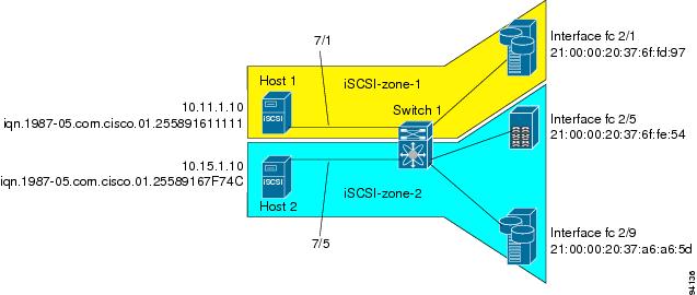
To configure scenario 1 (see Figure 4-44), follow these steps:
Step 1![]() Configure null authentication for all iSCSI hosts in Cisco MDS switches:
Configure null authentication for all iSCSI hosts in Cisco MDS switches:
Step 2![]() Configure iSCSI to dynamically import all Fibre Channel targets into the iSCSI SAN using auto-generated iSCSI target names:
Configure iSCSI to dynamically import all Fibre Channel targets into the iSCSI SAN using auto-generated iSCSI target names:
Step 3![]() Configure the Gigabit Ethernet interface in slot 7 port 1 with an IPv4 address and enable the interface:
Configure the Gigabit Ethernet interface in slot 7 port 1 with an IPv4 address and enable the interface:
Note![]() Host 2 is connected to this port.
Host 2 is connected to this port.
Step 4![]() Configure the iSCSI interface in slot 7 port 1 to identify all dynamic iSCSI initiators by their IP address, and enable the interface:
Configure the iSCSI interface in slot 7 port 1 to identify all dynamic iSCSI initiators by their IP address, and enable the interface:
Step 5![]() Configure the Gigabit Ethernet interface in slot 7 port 5 with the IPv4 address and enable the interface:
Configure the Gigabit Ethernet interface in slot 7 port 5 with the IPv4 address and enable the interface:
Step 6![]() Configure the iSCSI interface in slot 7 port 5 to identify all dynamic iSCSI initiators by node name and enable the interface:
Configure the iSCSI interface in slot 7 port 5 to identify all dynamic iSCSI initiators by node name and enable the interface:
Note![]() Host 1 is connected to this port.
Host 1 is connected to this port.
Step 7![]() Verify the available Fibre Channel targets (see Figure 4-44):
Verify the available Fibre Channel targets (see Figure 4-44):
Step 8![]() Create a zone named iscsi-zone-1 with host 1 and one Fibre Channel target in it:
Create a zone named iscsi-zone-1 with host 1 and one Fibre Channel target in it:
Note![]() Use the IP address of the host in zone membership configuration because the iSCSI interface is configured to identify all hosts based on IP address.
Use the IP address of the host in zone membership configuration because the iSCSI interface is configured to identify all hosts based on IP address.
Step 9![]() Create a zone named iscsi-zone-2 with host 2 and two Fibre Channel targets in it:
Create a zone named iscsi-zone-2 with host 2 and two Fibre Channel targets in it:
Note![]() Use the symbolic node name of the iSCSI host in zone membership configuration because the iSCSI interface is configured to identify all hosts based on node name.
Use the symbolic node name of the iSCSI host in zone membership configuration because the iSCSI interface is configured to identify all hosts based on node name.
Step 10![]() Create a zone set and add the two zones as members:
Create a zone set and add the two zones as members:
Step 11![]() Activate the zone set:
Activate the zone set:
Step 12![]() Display the active zone set:
Display the active zone set:
Note![]() The iSCSI hosts are not connected so they do not have an FC ID yet.
The iSCSI hosts are not connected so they do not have an FC ID yet.
Step 13![]() Bring up the iSCSI hosts (host 1 and host 2).
Bring up the iSCSI hosts (host 1 and host 2).
Step 14![]() Show all the iSCSI sessions (use the detail option for detailed information):
Show all the iSCSI sessions (use the detail option for detailed information):
Note![]() The last part of the auto-created target name is the Fibre Channel target's pWWN.
The last part of the auto-created target name is the Fibre Channel target's pWWN.
Step 15![]() Verify the details of the two iSCSI initiators:
Verify the details of the two iSCSI initiators:
Step 16![]() View the active zone set. The iSCSI initiators' FC IDs are resolved:
View the active zone set. The iSCSI initiators' FC IDs are resolved:
Step 17![]() The Fibre Channel name server shows the virtual N ports created for the iSCSI hosts:
The Fibre Channel name server shows the virtual N ports created for the iSCSI hosts:
Step 18![]() Verify the detailed output of the iSCSI initiator nodes in the Fibre Channel name server:
Verify the detailed output of the iSCSI initiator nodes in the Fibre Channel name server:
To configure scenario 1 (see Figure 4-44), follow these steps:
Step 1![]() Configure null authentication for all iSCSI hosts in Cisco MDS switches.
Configure null authentication for all iSCSI hosts in Cisco MDS switches.
a.![]() In Fabric Manager, choose End Devices > iSCSI in the Physical Attributes pane.
In Fabric Manager, choose End Devices > iSCSI in the Physical Attributes pane.
b.![]() Select none from the AuthMethod drop-down menu in the Information pane.
Select none from the AuthMethod drop-down menu in the Information pane.
c.![]() Click the Apply Changes icon.
Click the Apply Changes icon.
Step 2![]() Configure iSCSI to dynamically import all Fibre Channel targets into the iSCSI SAN using auto-generated iSCSI target names.
Configure iSCSI to dynamically import all Fibre Channel targets into the iSCSI SAN using auto-generated iSCSI target names.
a.![]() In Device Manager, click IP > iSCSI.
In Device Manager, click IP > iSCSI.
c.![]() Check the Dynamically Import FC Targets check box.
Check the Dynamically Import FC Targets check box.
Step 3![]() Configure the Gigabit Ethernet interface in slot 7 port 1 with an IPv4 address and enable the interface.
Configure the Gigabit Ethernet interface in slot 7 port 1 with an IPv4 address and enable the interface.
a.![]() In Fabric Manager, choose Switches > Interfaces > Gigabit Ethernet in the Physical Attributes pane.
In Fabric Manager, choose Switches > Interfaces > Gigabit Ethernet in the Physical Attributes pane.
b.![]() Select the IP Address tab in the Information pane and click Create Row.
Select the IP Address tab in the Information pane and click Create Row.
c.![]() Set the IP address and subnet mask for the Gigabit Ethernet interface in slot 7 port 1.
Set the IP address and subnet mask for the Gigabit Ethernet interface in slot 7 port 1.
e.![]() Select the General tab and select up from the Admin drop-down menu for the Gigabit Ethernet interface in slot 7 port 1.
Select the General tab and select up from the Admin drop-down menu for the Gigabit Ethernet interface in slot 7 port 1.
f.![]() Click the Apply Changes icon.
Click the Apply Changes icon.
Note![]() Host 2 is connected to this port.
Host 2 is connected to this port.
Step 4![]() Configure the iSCSI interface in slot 7 port 1 to identify all dynamic iSCSI initiators by their IP address, and enable the interface.
Configure the iSCSI interface in slot 7 port 1 to identify all dynamic iSCSI initiators by their IP address, and enable the interface.
a.![]() In Fabric Manager, choose Switches > Interfaces > FC Logical in the Physical Attributes pane.
In Fabric Manager, choose Switches > Interfaces > FC Logical in the Physical Attributes pane.
b.![]() Click the iSCSI tab in the Information pane.
Click the iSCSI tab in the Information pane.
c.![]() Select ipaddress from the Initiator ID Mode drop-down menu and click the Apply Changes icon.
Select ipaddress from the Initiator ID Mode drop-down menu and click the Apply Changes icon.
d.![]() In Device Manager, choose Interfaces > Ethernet and iSCSI.
In Device Manager, choose Interfaces > Ethernet and iSCSI.
f.![]() Select up from the Admin drop-down menu for the iSCSI interface in slot 7 port 1.
Select up from the Admin drop-down menu for the iSCSI interface in slot 7 port 1.
Step 5![]() Configure the Gigabit Ethernet interface in slot 7 port 5 with an IPv4 address and enable the interface.
Configure the Gigabit Ethernet interface in slot 7 port 5 with an IPv4 address and enable the interface.
a.![]() In Fabric Manager, choose Switches > Interfaces > Gigabit Ethernet in the Physical Attributes pane.
In Fabric Manager, choose Switches > Interfaces > Gigabit Ethernet in the Physical Attributes pane.
b.![]() Click the IP Address tab in the Information pane and click Create Row.
Click the IP Address tab in the Information pane and click Create Row.
c.![]() Set the IP address and subnet mask for the Gigabit Ethernet interface in slot 7 port 5.
Set the IP address and subnet mask for the Gigabit Ethernet interface in slot 7 port 5.
e.![]() Select the General tab and select up from the Admin drop-down menu for the Gigabit Ethernet interface in slot 7 port 5.
Select the General tab and select up from the Admin drop-down menu for the Gigabit Ethernet interface in slot 7 port 5.
f.![]() Click the Apply Changes icon.
Click the Apply Changes icon.
Step 6![]() Configure the iSCSI interface in slot 7 port 5 to identify all dynamic iSCSI initiators by node name and enable the interface.
Configure the iSCSI interface in slot 7 port 5 to identify all dynamic iSCSI initiators by node name and enable the interface.
a.![]() In Fabric Manager, choose Switches > Interfaces > FC Logical in the Physical Attributes pane.
In Fabric Manager, choose Switches > Interfaces > FC Logical in the Physical Attributes pane.
b.![]() Click the iSCSI tab in the Information pane.
Click the iSCSI tab in the Information pane.
c.![]() Select name from the Initiator ID Mode drop-down menu and click the Apply Changes icon.
Select name from the Initiator ID Mode drop-down menu and click the Apply Changes icon.
d.![]() In Device Manager, choose Interfaces > Ethernet and iSCSI.
In Device Manager, choose Interfaces > Ethernet and iSCSI.
f.![]() Select up from the Admin drop-down menu for the iSCSI interface in slot 7 port 5.
Select up from the Admin drop-down menu for the iSCSI interface in slot 7 port 5.
Note![]() Host 1 is connected to this port.
Host 1 is connected to this port.
Step 7![]() Verify the available Fibre Channel targets.
Verify the available Fibre Channel targets.
a.![]() In Device Manager, Choose FC > Name Server.
In Device Manager, Choose FC > Name Server.
Step 8![]() Create a zone named iscsi-zone-1 with host 1 and one Fibre Channel target in it.
Create a zone named iscsi-zone-1 with host 1 and one Fibre Channel target in it.
Note![]() Use the IP address of the host in zone membership configuration because the iSCSI interface is configured to identify all hosts based on IP address.
Use the IP address of the host in zone membership configuration because the iSCSI interface is configured to identify all hosts based on IP address.
a.![]() In Fabric Manager, choose Zones > Edit Local Full Zone Database.
In Fabric Manager, choose Zones > Edit Local Full Zone Database.
b.![]() Select VSAN 1 from the VSAN drop-down menu in the Edit Local Full Zone Database dialog box.
Select VSAN 1 from the VSAN drop-down menu in the Edit Local Full Zone Database dialog box.
c.![]() Select the Zones folder in the left navigation pane and click Insert.
Select the Zones folder in the left navigation pane and click Insert.
d.![]() Set the Zone Name field to iscsi-zone-1 and click OK.
Set the Zone Name field to iscsi-zone-1 and click OK.
e.![]() Select the iscsi-zone-1 folder in the left navigation pane and click Insert.
Select the iscsi-zone-1 folder in the left navigation pane and click Insert.
f.![]() Set the ZoneBy radio button to WWN.
Set the ZoneBy radio button to WWN.
g.![]() Set the Port WWN to the pWWN for the Fibre Channel target (that is, 21:00:00:20:37:6f:fd:97) and click Add.
Set the Port WWN to the pWWN for the Fibre Channel target (that is, 21:00:00:20:37:6f:fd:97) and click Add.
h.![]() Set the ZoneBy radio button to iSCSI IP Address/Subnet.
Set the ZoneBy radio button to iSCSI IP Address/Subnet.
i.![]() Set the IP Address/Mask field to the IP Address for Host 1 iSCSI initiator (10.11.1.10) and click Add.
Set the IP Address/Mask field to the IP Address for Host 1 iSCSI initiator (10.11.1.10) and click Add.
Step 9![]() Create a zone named iscsi-zone-2 with host 2 and two Fibre Channel targets in it.
Create a zone named iscsi-zone-2 with host 2 and two Fibre Channel targets in it.
Note![]() Use the symbolic node name of the iSCSI host in zone membership configuration because the iSCSI interface is configured to identify all hosts based on node name.
Use the symbolic node name of the iSCSI host in zone membership configuration because the iSCSI interface is configured to identify all hosts based on node name.
a.![]() In Fabric Manager, choose Zones > Edit Local Full Zone Database from the main menu.
In Fabric Manager, choose Zones > Edit Local Full Zone Database from the main menu.
b.![]() Select VSAN 2 from the VSAN drop-down menu in the Edit Local Full Zone Database dialog box.
Select VSAN 2 from the VSAN drop-down menu in the Edit Local Full Zone Database dialog box.
c.![]() Select the Zones folder in the left navigation pane and click Insert.
Select the Zones folder in the left navigation pane and click Insert.
d.![]() Set the Zone Name field to iscsi-zone-2 and click OK.
Set the Zone Name field to iscsi-zone-2 and click OK.
e.![]() Select the iscsi-zone-2 folder in the left navigation pane and click Insert.
Select the iscsi-zone-2 folder in the left navigation pane and click Insert.
f.![]() Set the ZoneBy radio button to WWN.
Set the ZoneBy radio button to WWN.
g.![]() Set the Port WWN to the pWWN for one of the Fibre Channel targets (for example, 21:00:00:20:37:6f:fe:5). and click Add.
Set the Port WWN to the pWWN for one of the Fibre Channel targets (for example, 21:00:00:20:37:6f:fe:5). and click Add.
h.![]() Set the Port WWN to the pWWN for another of the Fibre Channel targets (for example, 21:00:00:20:37:a6:a6:5d). and click Add.
Set the Port WWN to the pWWN for another of the Fibre Channel targets (for example, 21:00:00:20:37:a6:a6:5d). and click Add.
i.![]() Set the ZoneBy radio button to iSCSI name.
Set the ZoneBy radio button to iSCSI name.
j.![]() Set the Port Name field to the symbolic name for host 2 (iqn.1987-05.com.cisco:01.25589167f74c) and click Add.
Set the Port Name field to the symbolic name for host 2 (iqn.1987-05.com.cisco:01.25589167f74c) and click Add.
Step 10![]() Create a zone set, add the two zones as members, and activate the zone set.
Create a zone set, add the two zones as members, and activate the zone set.
Note![]() iSCSI interface is configured to identify all hosts based on node name.
iSCSI interface is configured to identify all hosts based on node name.
a.![]() In Fabric Manager, choose Zones > Edit Local Full Zone Database.
In Fabric Manager, choose Zones > Edit Local Full Zone Database.
b.![]() Select VSAN 1 from the VSAN drop-down menu in the Edit Local Full Zone Database dialog box.
Select VSAN 1 from the VSAN drop-down menu in the Edit Local Full Zone Database dialog box.
c.![]() Select the Zoneset folder in the left navigation pane and click Insert.
Select the Zoneset folder in the left navigation pane and click Insert.
d.![]() Set the Zoneset Name to zonset-iscsi and click OK.
Set the Zoneset Name to zonset-iscsi and click OK.
e.![]() Click on the zoneset-iscsi folder and click Insert.
Click on the zoneset-iscsi folder and click Insert.
f.![]() Set the Zone Name field to iscsi-zone-1 and click OK.
Set the Zone Name field to iscsi-zone-1 and click OK.
g.![]() Set the Zone Name field to iscsi-zone-2 and click OK.
Set the Zone Name field to iscsi-zone-2 and click OK.
h.![]() Click Activate to activate the new zone set.
Click Activate to activate the new zone set.
i.![]() Click Continue Activation to finish the activation.
Click Continue Activation to finish the activation.
Step 11![]() Bring up the iSCSI hosts (host 1 and host 2).
Bring up the iSCSI hosts (host 1 and host 2).
Step 12![]() Show all the iSCSI sessions.
Show all the iSCSI sessions.
a.![]() In Device Manager, choose Interfaces > Monitor > Ethernet.
In Device Manager, choose Interfaces > Monitor > Ethernet.
b.![]() Click the iSCSI connections tab to show all the iSCSI sessions.
Click the iSCSI connections tab to show all the iSCSI sessions.
c.![]() In Device Manager, choose IP > iSCSI and select the Session Initiators tab.
In Device Manager, choose IP > iSCSI and select the Session Initiators tab.
Step 13![]() In Fabric Manager, choose End Devices > iSCSI in the Physical Attributes pane to verify the details of the two iSCSI initiators
In Fabric Manager, choose End Devices > iSCSI in the Physical Attributes pane to verify the details of the two iSCSI initiators
Step 14![]() In Fabric Manager, choose Zones > Edit Local Full Zone Database to view the active zone set. The iSCSI initiators' FC IDs are resolved.
In Fabric Manager, choose Zones > Edit Local Full Zone Database to view the active zone set. The iSCSI initiators' FC IDs are resolved.
Step 15![]() In Device Manager, Choose FC > Name Server. The Fibre Channel name server shows the virtual N ports created for the iSCSI hosts.
In Device Manager, Choose FC > Name Server. The Fibre Channel name server shows the virtual N ports created for the iSCSI hosts.
Step 16![]() In Device Manager, Choose FC > Name Server.
In Device Manager, Choose FC > Name Server.
Step 17![]() Click the Advanced tab. Verify the detailed output of the iSCSI initiator nodes in the Fibre Channel name server.
Click the Advanced tab. Verify the detailed output of the iSCSI initiator nodes in the Fibre Channel name server.
Target Storage Device Requiring LUN Mapping
Sample scenario 2 assumes the following configuration (see Figure 4-45):
- Access control is based on Fibre Channel zoning.
- There is target-based LUN mapping or LUN masking.
- There is no iSCSI authentication (none).
- The iSCSI initiator is assigned to different VSANs.
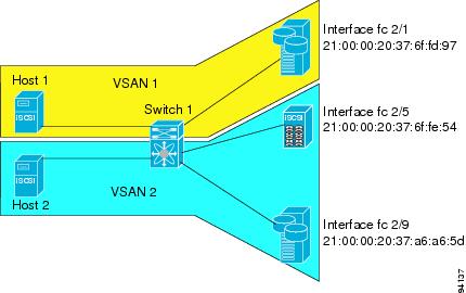
To configure scenario 2 (see Figure 4-45), follow these steps:
Step 1![]() Configure null authentication for all iSCSI hosts:
Configure null authentication for all iSCSI hosts:
Step 2![]() Configure iSCSI to dynamically import all Fibre Channel targets into the iSCSI SAN using auto-generated iSCSI target names:
Configure iSCSI to dynamically import all Fibre Channel targets into the iSCSI SAN using auto-generated iSCSI target names:
Step 3![]() Configure the Gigabit Ethernet interface in slot 7 port 1 with an IPv4 address and enable the interface:
Configure the Gigabit Ethernet interface in slot 7 port 1 with an IPv4 address and enable the interface:
Step 4![]() Configure the iSCSI interface in slot 7 port 1 to identify all dynamic iSCSI initiators by their IP address and enable the interface:
Configure the iSCSI interface in slot 7 port 1 to identify all dynamic iSCSI initiators by their IP address and enable the interface:
Step 5![]() Configure the Gigabit Ethernet interface in slot 7 port 5 with the IPv4 address and enable the interface:
Configure the Gigabit Ethernet interface in slot 7 port 5 with the IPv4 address and enable the interface:
Step 6![]() Configure the iSCSI interface in slot 7 port 5 to identify all dynamic iSCSI initiators by IP address and enable the interface:
Configure the iSCSI interface in slot 7 port 5 to identify all dynamic iSCSI initiators by IP address and enable the interface:
Step 7![]() Add static configuration for each iSCSI initiator:
Add static configuration for each iSCSI initiator:
Note![]() Host 1 is configured in VSAN 2.
Host 1 is configured in VSAN 2.
Step 8![]() View the configured WWNs:
View the configured WWNs:
Note![]() The WWNs are assigned by the system. The initiators are members of different VSANs.
The WWNs are assigned by the system. The initiators are members of different VSANs.
Step 9![]() Create a zone with host 1:
Create a zone with host 1:
Step 10![]() Add three members to the zone named iscsi-zone-1 :
Add three members to the zone named iscsi-zone-1 :
Note![]() Fibre Channel storage for zone membership for the iSCSI initiator, either the iSCSI symbolic node name or the pWWN, can be used. In this case, the pWWN is persistent.
Fibre Channel storage for zone membership for the iSCSI initiator, either the iSCSI symbolic node name or the pWWN, can be used. In this case, the pWWN is persistent.
Step 11![]() Create a zone with host 2 and two Fibre Channel targets:
Create a zone with host 2 and two Fibre Channel targets:
Note![]() If the host is in VSAN 2, the Fibre Channel targets and zone must also be in VSAN 2.
If the host is in VSAN 2, the Fibre Channel targets and zone must also be in VSAN 2.
Step 12![]() Activate the zone set in VSAN 2:
Activate the zone set in VSAN 2:
Step 13![]() Start the iSCSI clients on both hosts and verify that sessions come up.
Start the iSCSI clients on both hosts and verify that sessions come up.
Step 14![]() Display the iSCSI sessions to verify the Fibre Channel target and the configured WWNs.
Display the iSCSI sessions to verify the Fibre Channel target and the configured WWNs.
Step 15![]() Display the iSCSI initiator to verify the configured nWWN and pWWN:
Display the iSCSI initiator to verify the configured nWWN and pWWN:
| iSCSI Node name is iqn.1987-05.com.cisco:01.e41695d16b1a |
|
| Node WWN is 20:03:00:0b:fd:44:68:c2 (configured) <---------- |
|
| Virtual Port WWN is 20:02:00:0b:fd:44:68:c2 (configured) <---- |
Step 16![]() Check the Fibre Channel name server:
Check the Fibre Channel name server:
Step 17![]() Verify the details of the iSCSI initiator's FC ID in the name server:
Verify the details of the iSCSI initiator's FC ID in the name server:
Step 18![]() Check the Fibre Channel name server:
Check the Fibre Channel name server:
Step 19![]() Verify the details of the iSCSI initiator's FC ID in the name server:
Verify the details of the iSCSI initiator's FC ID in the name server:
Step 20![]() Verify that zoning has resolved the FC ID for the iSCSI client:
Verify that zoning has resolved the FC ID for the iSCSI client:
Step 21![]() Verify that the second initiator is connected to the two Fibre Channel targets in VSAN 2:
Verify that the second initiator is connected to the two Fibre Channel targets in VSAN 2:
To configure scenario 2 (see Figure 4-45), follow these steps:
Step 1![]() Configure null authentication for all iSCSI hosts.
Configure null authentication for all iSCSI hosts.
a.![]() In Fabric Manager, choose End Devices > iSCSI in the Physical Attributes pane.
In Fabric Manager, choose End Devices > iSCSI in the Physical Attributes pane.
b.![]() Select none from the AuthMethod drop-down menu in the Information pane.
Select none from the AuthMethod drop-down menu in the Information pane.
c.![]() Click the Apply Changes icon.
Click the Apply Changes icon.
Step 2![]() Configure iSCSI to dynamically import all Fibre Channel targets into the iSCSI SAN using auto-generated iSCSI target names.
Configure iSCSI to dynamically import all Fibre Channel targets into the iSCSI SAN using auto-generated iSCSI target names.
a.![]() In Device Manager, click IP > iSCSI.
In Device Manager, click IP > iSCSI.
c.![]() Check the Dynamically Import FC Targets check box.
Check the Dynamically Import FC Targets check box.
Step 3![]() Configure the Gigabit Ethernet interface in slot 7 port 1 with an IPv4 address and enable the interface.
Configure the Gigabit Ethernet interface in slot 7 port 1 with an IPv4 address and enable the interface.
a.![]() In Fabric Manager, choose Switches > Interfaces > Gigabit Ethernet in the Physical Attributes pane.
In Fabric Manager, choose Switches > Interfaces > Gigabit Ethernet in the Physical Attributes pane.
b.![]() Select the IP Address tab in the Information pane and click Create Row.
Select the IP Address tab in the Information pane and click Create Row.
c.![]() Set the IP address and subnet mask for the Gigabit Ethernet interface in slot 7 port 1.
Set the IP address and subnet mask for the Gigabit Ethernet interface in slot 7 port 1.
e.![]() Click the General tab and select up from the Admin drop-down menu for the Gigabit Ethernet interface in slot 7 port 1.
Click the General tab and select up from the Admin drop-down menu for the Gigabit Ethernet interface in slot 7 port 1.
f.![]() Click the Apply Changes icon.
Click the Apply Changes icon.
Step 4![]() Configure the iSCSI interface in slot 7 port 1 to identify all dynamic iSCSI initiators by their IP address and enable the interface.
Configure the iSCSI interface in slot 7 port 1 to identify all dynamic iSCSI initiators by their IP address and enable the interface.
a.![]() In Fabric Manager, choose Switches > Interfaces > FC Logical in the Physical Attributes pane.
In Fabric Manager, choose Switches > Interfaces > FC Logical in the Physical Attributes pane.
b.![]() Select the iSCSI tab in the Information pane.
Select the iSCSI tab in the Information pane.
c.![]() Select ipaddress from the Initiator ID Mode drop-down menu and click the Apply Changes icon.
Select ipaddress from the Initiator ID Mode drop-down menu and click the Apply Changes icon.
d.![]() In Device Manager, choose Interfaces > Ethernet and iSCSI.
In Device Manager, choose Interfaces > Ethernet and iSCSI.
f.![]() Select up from the Admin drop-down menu for the iSCSI interface in slot 7 port 1.
Select up from the Admin drop-down menu for the iSCSI interface in slot 7 port 1.
Step 5![]() Configure the Gigabit Ethernet interface in slot 7 port 5 with the IPv4 address and enable the interface.
Configure the Gigabit Ethernet interface in slot 7 port 5 with the IPv4 address and enable the interface.
a.![]() In Fabric Manager, choose Switches > Interfaces > Gigabit Ethernet in the Physical Attributes pane.
In Fabric Manager, choose Switches > Interfaces > Gigabit Ethernet in the Physical Attributes pane.
b.![]() Click the IP Address tab in the Information pane and click Create Row.
Click the IP Address tab in the Information pane and click Create Row.
c.![]() Set the IP address and subnet mask for the Gigabit Ethernet interface in slot 7 port 5.
Set the IP address and subnet mask for the Gigabit Ethernet interface in slot 7 port 5.
e.![]() Select the General tab and select up from the Admin drop-down menu for the Gigabit Ethernet interface in slot 7 port 5.
Select the General tab and select up from the Admin drop-down menu for the Gigabit Ethernet interface in slot 7 port 5.
f.![]() Click the Apply Changes icon.
Click the Apply Changes icon.
Step 6![]() Configure the iSCSI interface in slot 7 port 5 to identify all dynamic iSCSI initiators by IP address and enable the interface.
Configure the iSCSI interface in slot 7 port 5 to identify all dynamic iSCSI initiators by IP address and enable the interface.
a.![]() In Fabric Manager, choose Switches > Interfaces > FC Logical in the Physical Attributes pane.
In Fabric Manager, choose Switches > Interfaces > FC Logical in the Physical Attributes pane.
b.![]() Click the iSCSI tab in the Information pane.
Click the iSCSI tab in the Information pane.
c.![]() Select ipaddress from the Initiator ID Mode drop-down menu and click the Apply Changes icon.
Select ipaddress from the Initiator ID Mode drop-down menu and click the Apply Changes icon.
d.![]() In Device Manager, choose Interfaces > Ethernet and iSCSI.
In Device Manager, choose Interfaces > Ethernet and iSCSI.
f.![]() Select up from the Admin drop-down menu for the iSCSI interface in slot 7 port 5.
Select up from the Admin drop-down menu for the iSCSI interface in slot 7 port 5.
Step 7![]() Configure for static pWWN and nWWN for host 1.
Configure for static pWWN and nWWN for host 1.
a.![]() In Device Manager, choose IP > iSCSI.
In Device Manager, choose IP > iSCSI.
c.![]() Check the Node Address Persistent and Node Address System-assigned check boxes the Host 1 iSCSI initiator.
Check the Node Address Persistent and Node Address System-assigned check boxes the Host 1 iSCSI initiator.
Step 8![]() Configure for static pWWN for Host 2.
Configure for static pWWN for Host 2.
a.![]() In Device Manager, Choose IP > iSCSI.
In Device Manager, Choose IP > iSCSI.
c.![]() Right-click on the Host 2 iSCSI initiator and click Edit pWWN.
Right-click on the Host 2 iSCSI initiator and click Edit pWWN.
d.![]() Select 1 from the System-assigned Num field and click Apply.
Select 1 from the System-assigned Num field and click Apply.
Step 9![]() View the configured WWNs.
View the configured WWNs.
Note![]() The WWNs are assigned by the system. The initiators are members of different VSANs.
The WWNs are assigned by the system. The initiators are members of different VSANs.
a.![]() In Fabric Manager, choose End Devices > iSCSI in the Physical Attributes pane.
In Fabric Manager, choose End Devices > iSCSI in the Physical Attributes pane.
Step 10![]() Create a zone for Host 1 and the iSCSI target in VSAN 1.
Create a zone for Host 1 and the iSCSI target in VSAN 1.
Note![]() Use the IP address of the host in zone membership configuration because the iSCSI interface is configured to identify all hosts based on IP address.
Use the IP address of the host in zone membership configuration because the iSCSI interface is configured to identify all hosts based on IP address.
a.![]() In Fabric Manager, choose Zones > Edit Local Full Zone Database.
In Fabric Manager, choose Zones > Edit Local Full Zone Database.
b.![]() Select VSAN 1 from the VSAN drop-down menu in the Edit Local Full Zone Database dialog box.
Select VSAN 1 from the VSAN drop-down menu in the Edit Local Full Zone Database dialog box.
c.![]() Select the Zones folder in the left navigation pane and click Insert.
Select the Zones folder in the left navigation pane and click Insert.
d.![]() Set the Zone Name field to iscsi-zone-1 and click OK.
Set the Zone Name field to iscsi-zone-1 and click OK.
e.![]() Select the iscsi-zone-1 folder in the left navigation pane and click Insert.
Select the iscsi-zone-1 folder in the left navigation pane and click Insert.
f.![]() Set the ZoneBy radio button to WWN.
Set the ZoneBy radio button to WWN.
g.![]() Set the Port WWN to the pWWN for the Fibre Channel target (that is, 21:00:00:20:37:6f:fd:97). and click Add.
Set the Port WWN to the pWWN for the Fibre Channel target (that is, 21:00:00:20:37:6f:fd:97). and click Add.
h.![]() Set the ZoneBy radio button to iSCSI IP Address/Subnet.
Set the ZoneBy radio button to iSCSI IP Address/Subnet.
i.![]() Set the IP Address/Mask field to the IP Address for Host 1 iSCSI initiator (10.11.1.10) and click Add.
Set the IP Address/Mask field to the IP Address for Host 1 iSCSI initiator (10.11.1.10) and click Add.
Note![]() Fibre Channel storage for zone membership for the iSCSI initiator, either the iSCSI symbolic node name or the pWWN, can be used. In this case, the pWWN is persistent.
Fibre Channel storage for zone membership for the iSCSI initiator, either the iSCSI symbolic node name or the pWWN, can be used. In this case, the pWWN is persistent.
Step 11![]() Create a zone set in VSAN 1 and activate it.
Create a zone set in VSAN 1 and activate it.
a.![]() In Fabric Manager, choose Zones > Edit Local Full Zone Database.
In Fabric Manager, choose Zones > Edit Local Full Zone Database.
b.![]() Select VSAN 1 from the VSAN drop-down menu in the Edit Local Full Zone Database dialog box.
Select VSAN 1 from the VSAN drop-down menu in the Edit Local Full Zone Database dialog box.
c.![]() Select the Zoneset folder in the left navigation pane and click Insert.
Select the Zoneset folder in the left navigation pane and click Insert.
d.![]() Set the Zoneset Name to zonset-iscsi-1 and click OK.
Set the Zoneset Name to zonset-iscsi-1 and click OK.
e.![]() Click on the zoneset-iscsi-1 folder and click Insert.
Click on the zoneset-iscsi-1 folder and click Insert.
f.![]() Set the Zone Name field to iscsi-zone-1 and click OK.
Set the Zone Name field to iscsi-zone-1 and click OK.
g.![]() Click Activate to activate the new zone set.
Click Activate to activate the new zone set.
h.![]() Click Continue Activation to finish the activation.
Click Continue Activation to finish the activation.
Step 12![]() Create a zone with host 2 and two Fibre Channel targets.
Create a zone with host 2 and two Fibre Channel targets.
Note![]() If the host is in VSAN 2, the Fibre Channel targets and zone must also be in VSAN 2.
If the host is in VSAN 2, the Fibre Channel targets and zone must also be in VSAN 2.
Note![]() iSCSI interface is configured to identify all hosts based on node name.
iSCSI interface is configured to identify all hosts based on node name.
a.![]() In Fabric Manager, choose Zones > Edit Local Full Zone Database.
In Fabric Manager, choose Zones > Edit Local Full Zone Database.
b.![]() Select VSAN 2 from the VSAN drop-down menu in the Edit Local Full Zone Database dialog box.
Select VSAN 2 from the VSAN drop-down menu in the Edit Local Full Zone Database dialog box.
c.![]() Select the Zones folder in the left navigation pane and click Insert.
Select the Zones folder in the left navigation pane and click Insert.
d.![]() Set the Zone Name field to iscsi-zone-2 and click OK.
Set the Zone Name field to iscsi-zone-2 and click OK.
e.![]() Select the iscsi-zone-2 folder in the left navigation pane and click Insert.
Select the iscsi-zone-2 folder in the left navigation pane and click Insert.
f.![]() Set the ZoneBy radio button to WWN.
Set the ZoneBy radio button to WWN.
g.![]() Set the Port WWN to the pWWN for one of the Fibre Channel targets (for example, 21:00:00:20:37:6f:fe:5) and click Add.
Set the Port WWN to the pWWN for one of the Fibre Channel targets (for example, 21:00:00:20:37:6f:fe:5) and click Add.
h.![]() Set the Port WWN to the pWWN for another of the Fibre Channel targets (for example, 21:00:00:20:37:a6:a6:5d) and click Add.
Set the Port WWN to the pWWN for another of the Fibre Channel targets (for example, 21:00:00:20:37:a6:a6:5d) and click Add.
i.![]() Set the ZoneBy radio button to iSCSI IP Address/Subnet.
Set the ZoneBy radio button to iSCSI IP Address/Subnet.
j.![]() Set the IP Address/Mask field to the IP Address for Host 2 iSCSI initiator (10.15.1.11) and click Add.
Set the IP Address/Mask field to the IP Address for Host 2 iSCSI initiator (10.15.1.11) and click Add.
Step 13![]() Create a zone set in VSAN 2 and activate it.
Create a zone set in VSAN 2 and activate it.
a.![]() In Fabric Manager, choose Zones > Edit Local Full Zone Database.
In Fabric Manager, choose Zones > Edit Local Full Zone Database.
b.![]() Select VSAN 2 from the VSAN drop-down menu in the Edit Local Full Zone Database dialog box.
Select VSAN 2 from the VSAN drop-down menu in the Edit Local Full Zone Database dialog box.
c.![]() Select the Zoneset folder in the left navigation pane and click Insert.
Select the Zoneset folder in the left navigation pane and click Insert.
d.![]() Set the Zoneset Name to zonset-iscsi-2 and click OK.
Set the Zoneset Name to zonset-iscsi-2 and click OK.
e.![]() Click on the zoneset-iscsi-2 folder and click Insert.
Click on the zoneset-iscsi-2 folder and click Insert.
f.![]() Set the Zone Name field to iscsi-zone-2 and click OK.
Set the Zone Name field to iscsi-zone-2 and click OK.
g.![]() Click Activate to activate the new zone set.
Click Activate to activate the new zone set.
h.![]() Click Continue Activation to finish the activation.
Click Continue Activation to finish the activation.
Step 14![]() Start the iSCSI clients on both hosts.
Start the iSCSI clients on both hosts.
Step 15![]() Show all the iSCSI sessions.
Show all the iSCSI sessions.
a.![]() In Device Manager, choose Interface > Monitor > Ethernet and select the iSCSI connections tab to show all the iSCSI sessions.
In Device Manager, choose Interface > Monitor > Ethernet and select the iSCSI connections tab to show all the iSCSI sessions.
b.![]() In Device Manager, choose IP > iSCSI and select the Session Initiators tab.
In Device Manager, choose IP > iSCSI and select the Session Initiators tab.
Step 16![]() In Fabric Manager, choose End Devices > iSCSI in the Physical Attributes pane to verify the details of the two iSCSI initiators.
In Fabric Manager, choose End Devices > iSCSI in the Physical Attributes pane to verify the details of the two iSCSI initiators.
Step 17![]() In Fabric Manager, choose Zones > E dit Local Full Zone Database to view the active zone set. The iSCSI initiators' FC IDs are resolved.
In Fabric Manager, choose Zones > E dit Local Full Zone Database to view the active zone set. The iSCSI initiators' FC IDs are resolved.
Step 18![]() In Device Manager, choose FC > Name Server. The Fibre Channel name server shows the virtual N ports created for the iSCSI hosts.
In Device Manager, choose FC > Name Server. The Fibre Channel name server shows the virtual N ports created for the iSCSI hosts.
Step 19![]() In Device Manager, Choose FC > Name Server.
In Device Manager, Choose FC > Name Server.
Step 20![]() Click the Advanced tab. Verify the detailed output of the iSCSI initiator nodes in the Fibre Channel name server.
Click the Advanced tab. Verify the detailed output of the iSCSI initiator nodes in the Fibre Channel name server.
Overview of Internet Storage Name Service
Internet Storage Name Service (iSNS) allows your existing TCP/IP network to function more effectively as a SAN by automating the discovery, management, and configuration of iSCSI devices. To facilitate these functions, the iSNS server and client function as follows:
- The iSNS client registers iSCSI portals and all iSCSI devices accessible through them with an iSNS server.
- The iSNS server provides the following services for the iSNS client:
–![]() Remote domain discovery services
Remote domain discovery services
All iSCSI devices (both initiator and target) acting as iSNS clients, can register with an iSNS server. iSCSI initiators can then query the iSNS server for a list of targets. The iSNS server will respond with a list of targets that the querying client can access based on configured access control parameters.
A Cisco MDS 9000 Family switch can act as an iSNS client and register all available iSCSI targets with an external iSNS server. All switches in the Cisco MDS 9000 Family with Fibre Channel module with IPS ports or MPS-14/2 modules installed support iSNS server functionality. This allows external iSNS clients, such as an iSCSI initiator, to register with the switch and discover all available iSCSI targets in the SAN.
Overview of iSNS Client Functionality
Internet Storage Name Service (iSNS) allows your existing TCP/IP network to function more effectively as a SAN by automating the discovery, management, and configuration of iSCSI devices. The iSNS client registers iSCSI portals and all iSCSI devices accessible through them with an iSNS server. All iSCSI devices (both initiator and target) acting as iSNS clients can register with an iSNS server. When the iSNS client is unable to register or deregister objects with the iSNS server (for example, the client is unable to make a TCP connection to the iSNS server), it retries every minute to reregister all iSNS objects for the affected interfaces with the iSNS server.
The iSNS client functionality on each IPS interface (Gigabit Ethernet interface or subinterface or port channel) registers information with an iSNS server.
Once a profile is tagged to an interface, the switch opens a TCP connection to the iSNS server IP address (using the well-known iSNS port number 3205) in the profile and registers network entity and portal objects; a unique entity is associated with each IPS interface. The switch then searches the Fibre Channel name server (FCNS) database and switch configuration to find storage nodes to register with the iSNS server.
Statically mapped virtual targets are registered if the associated Fibre Channel pWWN is present in the FCNS database and no access control configuration prevents it. A dynamically mapped target is registered if dynamic target importing is enabled. See the “Presenting Fibre Channel Targets as iSCSI Targets” section for more details on how iSCSI imports Fibre Channel targets.
A storage node is deregistered from the iSNS server when it becomes unavailable when a configuration changes (such as access control change or dynamic import disabling) or the Fibre Channel storage port goes offline. It is registered again when the node comes back online.
When the iSNS client is unable to register or deregister objects with the iSNS server (for example, the client is unable to make a TCP connection to the iSNS server), it retries every minute to reregister all iSNS objects for the affected interfaces with the iSNS server. The iSNS client uses a registration interval value of 15 minutes. If the client fails to refresh the registration during this interval, the server will deregister the entries.
Untagging a profile also causes the network entity and portal to be deregistered from that interface.
Note![]() The iSNS client is not supported on a VRRP interface.
The iSNS client is not supported on a VRRP interface.
Creating an iSNS Client Profile
To create an iSNS profile, follow these steps:
|
|
|
|
|---|---|---|
To create an iSNS profile using Fabric Manager, follow these steps:
Step 1![]() Choose End Devices > iSCSI in the Physical Attributes pane.
Choose End Devices > iSCSI in the Physical Attributes pane.
You see the iSCSI configuration in the Information pane (see Figure 4-12).
Step 3![]() You see the iSNS profiles configured (see Figure 4-46).
You see the iSNS profiles configured (see Figure 4-46).
Figure 4-46 iSNS Profiles in Fabric Manager
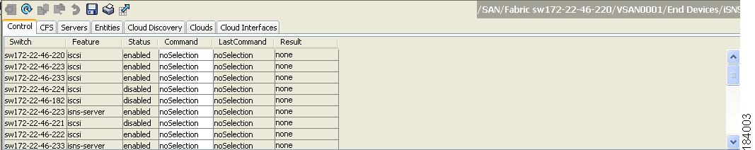
Step 4![]() Click the Create Row icon.
Click the Create Row icon.
You see the Create iSNS Profiles dialog box.
Step 5![]() Set the ProfileName field to the iSNS profile name that you want to create.
Set the ProfileName field to the iSNS profile name that you want to create.
Step 6![]() Set the ProfileAddr field to the IP address of the iSNS server.
Set the ProfileAddr field to the IP address of the iSNS server.
Step 7![]() Click Create to save these changes.
Click Create to save these changes.
To remove an iSNS profile, follow these steps:
|
|
|
|
|---|---|---|
To delete an iSNS profile using Fabric Manager, follow these steps:
Step 1![]() Choose End Devices > iSCSI from the Physical Attributes pane.
Choose End Devices > iSCSI from the Physical Attributes pane.
You see the iSCSI configuration in the Information pane (see Figure 4-12).
You see the iSNS profiles configured (see Figure 4-46).
Step 3![]() Right-click on the profile that you want to delete and click the Delete Row icon.
Right-click on the profile that you want to delete and click the Delete Row icon.
To tag a profile to an interface, follow these steps:
|
|
|
|
|---|---|---|
To tag a profile to an interface using Fabric Manager, follow these steps:
Step 1![]() Choose Switches > Interfaces > Gigabit Ethernet in the Physical Attributes pane.
Choose Switches > Interfaces > Gigabit Ethernet in the Physical Attributes pane.
You see the Gigabit Ethernet configuration in the Information pane.
You see the iSNS profiles configured for these interfaces (see Figure 4-47).
Figure 4-47 iSNS Profiles in Fabric Manager
Step 3![]() Set the iSNS ProfileName field to the iSNS profile name that you want to add to this interface.
Set the iSNS ProfileName field to the iSNS profile name that you want to add to this interface.
Step 4![]() Click the Apply Changes icon to save these changes.
Click the Apply Changes icon to save these changes.
To untag a profile from an interface, follow these steps:
|
|
|
|
|---|---|---|
Use the isns reregister command in EXEC mode to reregister associated iSNS objects with the iSNS server.
To untag a profile from an interface using Fabric Manager, follow these steps:
Step 1![]() Choose Switches > Interfaces > Gigabit Ethernet in the Physical Attributes pane.
Choose Switches > Interfaces > Gigabit Ethernet in the Physical Attributes pane.
You see the Gigabit Ethernet Configuration in the Information pane.
You see the iSNS profiles configured for these interfaces (see Figure 4-47).
Step 3![]() Right-click the iSNS ProfileName field that you want to untag and delete the text in that field.
Right-click the iSNS ProfileName field that you want to untag and delete the text in that field.
Step 4![]() Click the Apply Changes icon to save these changes.
Click the Apply Changes icon to save these changes.
Verifying iSNS Client Configuration
Use the show isns profile command to view configured iSNS profiles. Profile ABC has two portals registered with the iSNS server. Each portal corresponds to a particular interface. Profile XYZ has a specified iSNS server, but does not have any tagged interfaces configured (see Example 4-19 and Example 4-20).
Example 4-19 Displaying Information for Configured iSNS Profiles
Example 4-20 Displaying a Specified iSNS Profile
Use the show isns profile counters command to view all configured profiles with the iSNS PDU statistics for each tagged interface (see Example 4-21 and Example 4-22).
Example 4-21 Displaying Configured Profiles with iSNS Statistics
Example 4-22 Displaying iSNS Statistics for a Specified Profile
Use the show isns command to view all objects registered on the iSNS server and specified in the given profile (see Example 4-23).
Example 4-23 Displaying iSNS Queries
Use the show interface command to view the iSNS profile to which an interface is tagged (see Example 4-24).
Example 4-24 Displaying Tagged iSNS Interfaces
GigabitEthernet2/3 is up
Hardware is GigabitEthernet, address is 0005.3000.ae94
iSNS Server Functionality
When enabled, the iSNS server on the Cisco 9000 Family MDS switch tracks all registered iSCSI devices. As a result, iSNS clients can locate other iSNS clients by querying the iSNS server. The iSNS server also provides the following functionalities:
- Allows iSNS clients to register, deregister, and query other iSNS clients registered with the iSNS server.
- Provides centralized management for enforcing access control to provide or deny access to targets from specific initiators.
- Provides a notification mechanism for registered iSNS clients to receive change notifications on the status change of other iSNS clients.
- Provides a single access control configuration for both Fibre Channel and iSCSI devices.
- Discovers iSCSI targets that do not have direct IP connectivity to the iSCSI initiators.
Sample Scenario
The iSNS server provides uniform access control across Fibre Channel and iSCSI devices by utilizing both Fibre Channel zoning information and iSCSI access control information and configuration. An iSCSI initiator acting as an iSNS client only discovers devices it is allowed to access based on both sets of access control information. Figure 4-48 provides an example of this scenario.
Figure 4-48 Using iSNS Servers in the Cisco MDS Environment
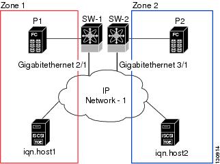
In Figure 4-48, iqn.host1 and iqn.host2 are iSCSI initiators. P1 and P2 are Fibre Channel targets. The two initiators are in different zones: Zone 1 consists of iqn.host1 and target P1, and Zone 2 consists of iqn.host2 and target P2. iSNS server functionality is enabled on both switches, SW-1 and SW-2. The registration process proceeds as follows:
1.![]() Initiator iqn.host1 registers with SW-1, port Gigabitethernet2/1.
Initiator iqn.host1 registers with SW-1, port Gigabitethernet2/1.
2.![]() Initiator iqn.host2 registers with SW-2, port Gigabitethernet3/1.
Initiator iqn.host2 registers with SW-2, port Gigabitethernet3/1.
3.![]() Initiator iqn.host1 issues an iSNS query to SW-1 to determine all accessible targets.
Initiator iqn.host1 issues an iSNS query to SW-1 to determine all accessible targets.
4.![]() The iSNS server in turn queries the Fibre Channel name server (FCNS) to obtain a list of devices that are accessible (that is, in the same zone) by the query originator. This query yields only P1.
The iSNS server in turn queries the Fibre Channel name server (FCNS) to obtain a list of devices that are accessible (that is, in the same zone) by the query originator. This query yields only P1.
5.![]() The iSNS server then queries its own database to convert the Fibre Channel devices to the corresponding iSCSI targets. This is based on the iSCSI configuration, such as virtual-target and its access control setting or whether the dynamic Fibre Channel target import feature is enabled or disabled.
The iSNS server then queries its own database to convert the Fibre Channel devices to the corresponding iSCSI targets. This is based on the iSCSI configuration, such as virtual-target and its access control setting or whether the dynamic Fibre Channel target import feature is enabled or disabled.
6.![]() The iSNS server sends a response back to the query initiator. This response contains a list all iSCSI portals known to the iSNS server. This means iqn.host1 can choose to log in to target P1 through either SW-1 (at Gigabitethernet 2/1) or SW-2 (at Gigabitethernet 3/1).
The iSNS server sends a response back to the query initiator. This response contains a list all iSCSI portals known to the iSNS server. This means iqn.host1 can choose to log in to target P1 through either SW-1 (at Gigabitethernet 2/1) or SW-2 (at Gigabitethernet 3/1).
7.![]() If the initiator chooses to log in to SW-1 and later that port becomes inaccessible (for example, Gigabitethernet 2/1 goes down), the initiator has the choice to move to connect to target P1 through port Gigabitethernet 3/1 on SW-2 instead.
If the initiator chooses to log in to SW-1 and later that port becomes inaccessible (for example, Gigabitethernet 2/1 goes down), the initiator has the choice to move to connect to target P1 through port Gigabitethernet 3/1 on SW-2 instead.
8.![]() If the target either goes down or is removed from the zone, the iSNS server sends out an iSNS State Change Notification (SCN) message to the initiator so that the initiator can remove the session.
If the target either goes down or is removed from the zone, the iSNS server sends out an iSNS State Change Notification (SCN) message to the initiator so that the initiator can remove the session.
Configuring an iSNS Server
This section describe how to configure an iSNS server on a Cisco MDS 9000 Family switch.
Enabling an iSNS Server
Before the iSNS server feature can be enabled, iSCSI must be enabled (see the “Enabling iSCSI” section). When you disable iSCSI, iSNS is automatically disabled. When the iSNS server is enabled on a switch, every IPS port whose corresponding iSCSI interface is up is capable of servicing iSNS registration and query requests from external iSNS clients.
To enable the iSNS server, follow these steps:
|
|
|
|
|---|---|---|
To enable the iSNS server using Fabric Manager, follow these steps:
Step 1![]() Choose End Devices > iSNS.
Choose End Devices > iSNS.
You see the iSNS configuration in the Information pane.
Step 2![]() Click the Control tab and select enable from the Command drop-down menu for the iSNS server feature.
Click the Control tab and select enable from the Command drop-down menu for the iSNS server feature.
Step 3![]() Click the Apply Changes icon to save this change.
Click the Apply Changes icon to save this change.
Note![]() If you are using VRRP IPv4 addresses for discovering targets from iSNS clients, ensure that the IP address is created using the secondary option (see “Adding Virtual Router IP Addresses” section).
If you are using VRRP IPv4 addresses for discovering targets from iSNS clients, ensure that the IP address is created using the secondary option (see “Adding Virtual Router IP Addresses” section).
iSNS Configuration Distribution
You can use the CFS infrastructure to distribute the iSCSI initiator configuration to iSNS servers across the fabric. This allows the iSNS server running on any switch to provide a querying iSNS client a list of iSCSI devices available anywhere on the fabric. For information on CFS, see the Cisco Fabric Manager System Management Configuration Guide and Cisco MDS 9000 Family NX-OS System Management Configuration Guide.
To enable iSNS configuration distribution using, follow these steps:
To enable iSNS configuration distribution using Fabric Manager, follow these steps:
Step 1![]() Choose End Devices > iSNS.
Choose End Devices > iSNS.
You see the iSNS configuration in the Information pane.
Step 2![]() Click the CFS tab and select enable from the Admin drop-down menu for iSNS.
Click the CFS tab and select enable from the Admin drop-down menu for iSNS.
Step 3![]() Select enable from the Global drop-down menu for iSNS.
Select enable from the Global drop-down menu for iSNS.
Step 4![]() Click the Apply Changes icon to save this change.
Click the Apply Changes icon to save this change.
Configuring the ESI Retry Count
The iSNS client registers information with its configured iSNS server using an iSNS profile. At registration, the client can indicate an entity status inquiry (ESI) interval of 60 seconds or more. If the client registers with an ESI interval set to zero (0), then the server does not monitor the client using ESI. In such cases, the client’s registrations remain valid until explicitly deregistered or the iSNS server feature is disabled.
The ESI retry count is the number of times the iSNS server queries iSNS clients for their entity status. The default ESI retry count is 3. The client sends the server a response to indicate that it is still alive. If the client fails to respond after the configured number of retries, the client is deregistered from the server.
To configure the ESI retry count for an iSNS server, follow these steps:
|
|
|
|
|---|---|---|
Configures the ESI to retry contacting the client up to 6 times. The range is 1 to 10. |
||
Configuring a Registration Period
The iSNS client specifies the registration period with the iSNS Server. The iSNS Server keeps the registration active until the end of this period. If there are no commands from the iSNS client during this period, then the iSNS server removes the client registration from its database.
If the iSNS client does not specify a registration period, the iSNS server assumes a default value of 0, which keeps the registration active indefinitely. You can also manually configure the registration period on the MDS iSNS Server.
To configure the registration period on an iSNS Server, follow these steps:
To configure the registration period on an iSNS Server using Fabric Manager, follow these steps:
Step 1![]() Choose E nd Devices > iSNS.
Choose E nd Devices > iSNS.
You see the iSNS configuration in the Information pane.
You see the configured iSNS servers.
Step 3![]() Set the ESI NonResponse Threshold field to the ESI retry count value.
Set the ESI NonResponse Threshold field to the ESI retry count value.
Step 4![]() Click the Apply Changes icon to save this change.
Click the Apply Changes icon to save this change.
iSNS Client Registration and Deregistration
You can use the show isns database command to display all registered iSNS clients and their associated configuration.
An iSNS client cannot query the iSNS server until it has registered. iSNS client deregistration can occur either explicitly or when the iSNS server detects that it can no longer reach the client (through ESI monitoring).
iSNS client registration and deregistration result in status change notifications (SCNs) being generated to all interested iSNS clients.
Target Discovery
iSCSI initiators discover targets by issuing queries to the iSNS server. The server supports DevGetNext requests to search the list of targets and DevAttrQuery to determine target and portal details, such as the IP address or port number to which to connect.
On receiving a query request from the iSCSI client, the iSNS server queries the Fibre Channel Name Server (FCNS) to obtain a list of Fibre Channel targets that are accessible by the querying initiator. The result of this query depends on zoning configuration currently active and current configuration(s) of the initiator. The iSNS server will subsequently use the iSCSI target configuration(s) (virtual target and dynamic import configuration) to translate the Fibre Channel target to an equivalent iSCSI target. At this stage it also applies any access control configured for the virtual target. A response message with the target details is then sent back to the query initiator.
The iSNS server sends a consolidated response containing all possible targets and portals to the querying initiator. For example, if a Fibre Channel target is exported as different iSCSI targets on different IPS interfaces, the iSNS server will respond with a list of all possible iSCSI targets and portals.
In order to keep the list of targets updated, the iSNS server sends state change notifications (SCN) to the client whenever an iSCSI target becomes reachable or unreachable. The client is then expected to rediscover its list of accessible targets by initiating another iSNS query. Reachability of iSCSI targets changes when any one of the following occurs:
Verifying the iSNS Server Configuration
Use the show isns config command to view the ESI interval and the summary information about the iSNS database contents (see Example 4-25).
Example 4-25 Displaying the iSNS Server Configuration of ESI Interval and Database Contents
Use the show isns database command to view detailed information about the contents of the iSNS database (see Example 4-26 through Example 4-29). This command displays the full iSNS database giving all the entities, nodes, and portals registered in the database. This command without options only displays explicitly registered objects. The asterisk next to the VSAN ID indicates that the iSCSI node is in the default zone for that VSAN.
Example 4-26 Displaying Explicitly Registered Objects
Example 4-27 Displaying the Full Database with Both Registered and Configured Nodes and Portals
Note![]() The local option is only available for virtual targets.
The local option is only available for virtual targets.
Example 4-28 Displaying the Virtual Target Information in a Local Switch
Example 4-29 Displaying Virtual Target for a Specified Switch
Use the show isns node command to display attributes of nodes registered with the iSNS server (see Example 4-30 through Example 4-32). If you do not specify any options, the server displays the name and node type attribute in a compact format; one per line.
Example 4-30 Displaying Explicitly Registered Objects
Example 4-31 Displaying the Specified Node
Example 4-32 Displaying the Attribute Details for All Nodes
Use the show isns portal command to display the attributes of a portal along with its accessible nodes (see Example 4-33 through Example 4-37). You can specify portals by using the switch WWN-interface combination or the IP address-port number combination.
Example 4-33 Displaying the Attribute Information for All Portals
Example 4-34 Displaying Detailed Attribute Information for All Portals
Example 4-35 Displaying Virtual Portals
Example 4-36 Displaying Virtual Portals for a Specified Switch
Example 4-37 Displaying Detailed Information for the Virtual Portals in a Specified Switch
Use the show isns entity command to display the attributes of an entity along with the list of portals and nodes in that entity (see Example 4-38 through Example 4-42). If you do not specify any option, this command displays the entity ID and number of nodes or portals associated with the entity in a compact format; one per line.
Example 4-38 Displaying All Registered Entries
Example 4-39 Displaying All Entities in the Database
Example 4-40 Displaying the Entity with a Specified ID
Example 4-41 Displaying Detailed Information for All Entities in the Database
Example 4-42 Displaying Virtual Entities
Use the show iscsi global config command to display information about import targets (see Example 4-43 and Example 4-44).
Example 4-43 Displaying the Import Target Settings for a Specified Switch
Example 4-44 Displaying the Import Target Settings for All Switches
Use the show cfs peers command to display CFS peers switch information about the iSNS application (see Example 4-45).
Example 4-45 Displaying the CFS Peer Switch Information for the iSNS Application
iSNS Cloud Discovery
You can configure iSNS cloud discovery to automate the process of discovering iSNS servers in the IP network.
Cloud Discovery
When an iSNS server receives a query request, it responds with a list of available targets and the portals through which the initiator can reach the target. The IP network configuration outside the MDS switch may result in only a subset of Gigabit Ethernet interfaces being reachable from the initiator. To ensure that the set of portals returned to the initiator is reachable, the iSNS server needs to know the set of Gigabit Ethernet interfaces that are reachable from a given initiator.
Note![]() iSNS Cloud Discovery is not supported on the Cisco Fabric Switch for IBM BladeCenter and Cisco Fabric Switch for HP c-Class BladeSystem.
iSNS Cloud Discovery is not supported on the Cisco Fabric Switch for IBM BladeCenter and Cisco Fabric Switch for HP c-Class BladeSystem.
The iSNS cloud discovery feature provides information to the iSNS server on the various interfaces reachable from an initiator by partitioning the interfaces on a switch into disjointed IP clouds. This discovery is achieved by sending messages to all other known IPS ports that are currently up and, depending on the response (or the lack of it), determines if the remote IPS port is in the same IP network or in a different IP network.
Cloud discovery is initiated when the following events occur:
- Manual requests from the CLI initiate cloud discovery from the CLI. This action causes the destruction of existing memberships and makes new ones.
- Auto-discovery of the interface results in an interface being assigned to its correct cloud. All other cloud members are not affected. The membership of each cloud is built incrementally and is initiated by the following events:
–![]() A Gigabit Ethernet interface comes up. This can be a local or remote Gigabit Ethernet interface.
A Gigabit Ethernet interface comes up. This can be a local or remote Gigabit Ethernet interface.
–![]() The IP address of a Gigabit Ethernet interface changes.
The IP address of a Gigabit Ethernet interface changes.
–![]() The VRRP configuration on a port changes.
The VRRP configuration on a port changes.
The iSNS server distributes cloud and membership information across all the switches using CFS. Therefore, the cloud membership view is the same on all the switches in the fabric.
Note![]() For CFS distribution to operate correctly for iSNS cloud discovery, all switches in the fabric must be running Cisco SAN-OS Release 3.0(1) or NX-OS 4.1(1b) and later.
For CFS distribution to operate correctly for iSNS cloud discovery, all switches in the fabric must be running Cisco SAN-OS Release 3.0(1) or NX-OS 4.1(1b) and later.
Configuring iSNS Cloud Discovery
This section describes how to configure iSNS cloud discovery and includes the following topics:
Enabling iSNS Cloud Discovery
To enable iSNS cloud discovery, follow these steps:
|
|
|
|
|---|---|---|
To enable iSNS cloud discovery using Fabric Manager, follow these steps:
Step 1![]() Choose End Devices > iSNS.
Choose End Devices > iSNS.
You see the iSNS configuration in the Information pane.
Step 2![]() Click the Control tab and select enable from the Command drop-down menu for the cloud discovery feature.
Click the Control tab and select enable from the Command drop-down menu for the cloud discovery feature.
Step 3![]() Click the Apply Changes icon to save this change.
Click the Apply Changes icon to save this change.
Initiating On-Demand iSNS Cloud Discovery
To initiate on-demand iSNS cloud discovery, use the cloud discover command in EXEC mode.
The following example shows how to initiate on-demand cloud discovery for the entire fabric:
To initiate on-demand iSNS cloud discovery using Fabric Manager, follow these steps:
Step 1![]() Choose End Devices > iSNS.
Choose End Devices > iSNS.
You see the iSNS configuration in the Information pane.
Step 2![]() Click the Cloud Discovery tab and check the Manual Discovery check box.
Click the Cloud Discovery tab and check the Manual Discovery check box.
Step 3![]() Click the Apply Changes icon to save this change.
Click the Apply Changes icon to save this change.
Configuring Automatic iSNS Cloud Discovery
To configure automatic iSNS cloud discovery, follow these steps:
|
|
|
|
|---|---|---|
To configure automatic iSNS cloud discovery using Fabric Manager, follow these steps:
Step 1![]() Choose End Devices > iSNS.
Choose End Devices > iSNS.
You see the iSNS configuration in the Information pane.
Step 2![]() Click the Cloud Discovery tab and check the AutoDiscovery check box.
Click the Cloud Discovery tab and check the AutoDiscovery check box.
Step 3![]() Click the Apply Changes icon to save this change.
Click the Apply Changes icon to save this change.
Verifying Automatic iSNS Cloud Discovery Configuration
To verify the automatic iSNS cloud discovery configuration, use the show cloud discovery config command:
Configuring iSNS Cloud Discovery Distribution
To configure iSNS cloud discovery distribution using CFS, follow these steps:
|
|
|
|
|---|---|---|
To configure iSNS cloud discovery CFS distribution using Fabric Manager, follow these steps:
Step 1![]() Choose End Devices > iSNS.
Choose End Devices > iSNS.
You see the iSNS configuration in the Information pane.
Step 2![]() Click the CFS tab and select enable from the Admin drop-down menu for the cloud discovery feature.
Click the CFS tab and select enable from the Admin drop-down menu for the cloud discovery feature.
Step 3![]() Select enable from the Global drop-down menu for the cloud discovery feature.
Select enable from the Global drop-down menu for the cloud discovery feature.
Step 4![]() Click the Apply Changes icon to save this change.
Click the Apply Changes icon to save this change.
Configuring iSNS Cloud Discovery Message Types
You can configure iSNS cloud discovery the type of message to use. By default, iSNS cloud discovery uses ICMP.
To configure iSNS cloud discovery message types, follow these steps:
|
|
|
|
|---|---|---|
Verifying Cloud Discovery Status
Use the show cloud discovery status command to verify the status of the cloud discovery operation:
Verifying Cloud Discovery Membership
Use the show cloud membership all command to verify the cloud membership for the switch:
Use the show cloud membership unresolved command to verify the unresolved membership on the switch:
Displaying Cloud Discovery Statistics
Use the show cloud discovery statistics command to display the statistics for the cloud discovery operation:
Default Settings
Table 4-2 lists the default settings for iSCSI parameters.
Table 4-3 lists the default settings for iSLB parameters.
|
|
|
|---|---|
 Feedback