- Title
- Table of Contents
- New and Changed Information
- Preface
-
- Configuring Basic MPLS TE
- Configuring Automatic Bandwidth Adjustment for MPLS TE Tunnels
- Configuring MPLS TE RSVP
- Configuring the Path Selection Metric for MPLS TE Tunnels
- Configuring LSP Attributes for MPLS TE
- Configuring MPLS TE Verbatim Paths
- Configuring MPLS TE Forwarding Adjacency
- Configuring MPLS TE Path Protection
- Configuring MPLS TE Fast Reroute Link and Node Protection
-
- Configuring Any Transport over MPLS
- Configuring Any Transport over MPLS Pseudowire Provisioning
- Configuring Ethernet over MPLS
- Configuring EoMPLS Layer 2 VPN Graceful Restart
- Configuring Virtual Private LAN Service
- Configuring Layer 2 VPN Pseudowire Redundancy
- Configuring Layer 2 VPN VPLS Dual-Homing with a vPC
- Configuration Limits for Cisco NX-OS MPLS
- RFCs
- Finding Feature Information
- Information About MPLS TE Fast Reroute Link and Node Protection
- Fast Reroute
- Link Protection
- Node Protection
- Bandwidth Protection
- Features of Fast Reroute Link and Node Protection
- Fast Reroute Operation
- Fast Reroute Activation
- Backup Tunnels Terminating at Different Destinations
- Backup Tunnels Terminating at the Same Destination
- Backup Tunnel Selection Procedure
- Bandwidth Protection
- Load Balancing on Limited-Bandwidth Backup Tunnels
- Load Balancing on Unlimited-Bandwidth Backup Tunnels
- Pool Type and Backup Tunnels
- Tunnel Selection Priorities
- Bandwidth Protection Considerations
- Example: Enabling Fast Reroute for all Tunnels
- Example: Creating an NHOP Backup Tunnel
- Example: Creating an NNHOP Backup Tunnel
- Example: Assigning Backup Tunnels to a Protected Interface
- Example: Associating the Backup Bandwidth and Pool Type with Backup Tunnels
- Example: Configuring Backup Bandwidth Protection
- Example: Configuring RSVP Hello
- LSPs Do Not Become Active; They Remain Ready
- Primary Tunnel Does Not Select Backup Tunnel That Is Up
- Enhanced RSVP Commands Display Useful Information
- RSVP Hello Detects When a Neighboring Node Is Not Reachable
- Hello Instances Have Not Been Created
- “No entry at index” (error may self-correct, RRO may not yet have propagated from downstream node of interest)” Error Message is Displayed at the Point of Local Repair
- “Couldn’t get rsbs” (error may self-correct when Resv arrives)” Error Message is Displayed at the Point of Local Repair (PLR)
Configuring MPLS TE Fast Reroute Link and Node Protection
This chapter describes how to configure Multiprotocol Label Switching (MPLS) traffic engineering (TE) fast reroute link and node protection on Cisco NX-OS devices.
This chapter includes the following sections:
- Finding Feature Information, page 18-272
- Information About MPLS TE Fast Reroute Link and Node Protection, page 18-273
- Licensing Requirements for MPLS TE Fast Reroute Link and Node Protection, page 18-285
- Prerequisites for MPLS TE Fast Reroute Link and Node Protection, page 18-285
- Guidelines and Limitations for MPLS TE Fast Reroute Link and Node Protection, page 18-286
- Configuring MPLS TE Fast Reroute Link and Node Protection, page 18-286
- Verifying the MPLS TE Fast Reroute Link and Node Protection Configuration, page 18-292
- Configuration Examples of MPLS TE Fast Reroute Link and Node Protection, page 18-295
- Troubleshooting Tips
- Additional References for MPLS TE Fast Reroute Link and Node Protection, page 18-301
- Feature History for MPLS TE Fast Reroute Link and Node Protection, page 18-302
Finding Feature Information
Your software release might not support all the features documented in this module. For the latest caveats and feature information, see the Bug Search Tool at https://tools.cisco.com/bugsearch/ and the release notes for your software release. To find information about the features documented in this module, and to see a list of the releases in which each feature is supported, see the “New and Changed Information” chapter or the Feature History table below.
Information About MPLS TE Fast Reroute Link and Node Protection
Fast reroute link and node protection provides link protection (backup tunnels that bypass only a single link of the label switched path [LSP]), node protection (backup tunnels that bypass next-hop nodes along LSPs), and the following fast reroute (FRR) features:
This section includes the following topics:
- Fast Reroute, page 18-273
- Link Protection, page 18-273
- Node Protection, page 18-274
- Bandwidth Protection, page 18-274
- Features of Fast Reroute Link and Node Protection, page 18-275
- Fast Reroute Operation
Fast Reroute
Fast Reroute (FRR) is a mechanism for protecting MPLS TE LSPs from link and node failures by locally repairing the LSPs at the point of failure, allowing data to continue to flow on them while their headend routers try to establish new end-to-end LSPs to replace them. FRR locally repairs the protected LSPs by rerouting them over backup tunnels that bypass failed links or node.
Link Protection
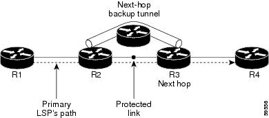
Backup tunnels that bypass only a single link of the LSP’s path provide link protection. They protect LSPs if a link along their path fails by rerouting the LSP’s traffic to the next hop (bypassing the failed link). These tunnels are referred to as next-hop (NHOP) backup tunnels because they terminate at the LSP’s next hop beyond the point of failure. Figure 18-1 shows an NHOP backup tunnel.
Figure 18-1 NHOP Backup Tunnel
Node Protection
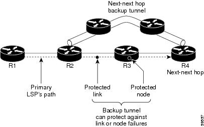
FRR provides node protection for LSPs. Backup tunnels that bypass next-hop nodes along LSP paths are called next-next-hop (NNHOP) backup tunnels because they terminate at the node following the next-hop node of the LSP paths, bypassing the next-hop node. They protect LSPs if a node along their path fails by enabling the node upstream of the failure to reroute the LSPs and their traffic around the failed node to the next-next hop. FRR supports the use of BFD to accelerate the detection of node failures. NNHOP backup tunnels also provide protection from link failures, because they bypass the failed link and the node.
Figure 18-2 shows an NNHOP backup tunnel.
Figure 18-2 NNHOP Backup Tunnel
If an LSP is using a backup tunnel and something changes so that the LSP is no longer appropriate for the backup tunnel, the LSP is torn down. Such changes are the following:
Bandwidth Protection
NHOP and NNHOP backup tunnels can be used to provide bandwidth protection for rerouted LSPs, which is referred to as backup bandwidth. You can associate backup bandwidth with NHOP or NNHOP backup tunnels to inform the router of the amount of backup bandwidth a particular backup tunnel can protect. When a router maps LSPs to backup tunnels, bandwidth protection ensures that an LSP uses a given backup tunnel only if there is sufficient backup bandwidth. The router selects which LSPs use which backup tunnels in order to provide maximum bandwidth protection. The router determines the best way to map LSPs onto backup tunnels in order to maximize the number of LSPs that can be protected. For information about mapping tunnels and assigning backup bandwidth, see the “Backup Tunnel Selection Procedure”.
LSPs that have the bandwidth protection desired bit set have a higher right to select backup tunnels that provide bandwidth protection; that is, those LSPs can preempt other LSPs that do not have that bit set. For more information, see the “Prioritizing Which LSPs Obtain Backup Tunnels with Bandwidth Protection”.
Features of Fast Reroute Link and Node Protection
Fast reroute link and node protection has the following features:
Backup Tunnel Support
This section includes the following topics:
- Backup Tunnels Can Terminate at the Next-Next Hop to Support FRR, page 18-275
- Multiple Backup Tunnels Can Protect the Same Interface, page 18-275
- Backup Tunnels Provide Scalability, page 18-276
Backup Tunnels Can Terminate at the Next-Next Hop to Support FRR
Backup tunnels that terminate at the next-next hop protect both the downstream link and node, which provides protection for link and node failures. For more detailed information, see the “Node Protection”.
Multiple Backup Tunnels Can Protect the Same Interface
There is no limit (except memory limitations) to the number of backup tunnels that can protect a given interface. In many topologies, support for node protection requires supporting multiple backup tunnels per protected interface. These backup tunnels can terminate at the same destination or at different destinations. For a given protected interface, you can configure multiple NHOP or NNHOP backup tunnels, which allow redundancy and load balancing.
In addition to being required for node protection, the protection of an interface by multiple backup tunnels provides the following benefits:
- Redundancy—If one backup tunnel is down, other backup tunnels protect LSPs.
- Increased backup capacity—If the protected interface is a high-capacity link and no single backup path exists with an equal capacity, multiple backup tunnels can protect that one high-capacity link. The LSPs using this link fails over to different backup tunnels, allowing all of the LSPs to have adequate bandwidth protection during the failure (rerouting). If bandwidth protection is not desired, the router spreads LSPs across all available backup tunnels (that is, there is load balancing across backup tunnels). For more details, see the “Backup Tunnel Selection Procedure”.
Examples are shown in the “Backup Tunnels Terminating at Different Destinations” and the “Backup Tunnels Terminating at the Same Destination”.
Backup Tunnels Provide Scalability
A backup tunnel can protect multiple LSPs and multiple interfaces. This feature is called many-to-one (N:1) protection. An example of N:1 protection is when one backup tunnel protects 5000 LSPs, where each router along the backup path maintains one additional tunnel.
One-to-one protection is when a separate backup tunnel must be used for each LSP that needs protection. N:1 protection has significant scalability advantages over one-to-one (1:1) protection. An example of 1:1 protection is when 5000 backup tunnels protect 5000 LSPs, where each router along the backup path must maintain the state for an additional 5000 tunnels.
Backup Bandwidth Protection
Backup bandwidth protection allows you to give LSPs that carry certain kinds of data (such as voice) priority for using backup tunnels. Backup bandwidth protection has the following capabilities:
- Bandwidth Protection on Backup Tunnels, page 18-276
- Bandwidth Pool Specifications for Backup Tunnels, page 18-276
- Semidynamic Backup Tunnel Paths, page 18-276
- Prioritizing Which LSPs Obtain Backup Tunnels with Bandwidth Protection, page 18-276
Bandwidth Protection on Backup Tunnels
Rerouted LSPs not only have their packets delivered during a failure, but the quality of service can also be maintained.
Bandwidth Pool Specifications for Backup Tunnels
You can restrict the types of LSPs that can use a given backup tunnel. Backup tunnels can be restricted so that only LSPs that use global-pool bandwidth can use them. This feature allows different backup tunnels to be used for voice and data. Example: The backup tunnel used for voice could provide bandwidth protection, and the backup tunnel used for data could not provide bandwidth protection.
Semidynamic Backup Tunnel Paths
The path of a backup tunnel can be configured to be determined dynamically, which can be done by using the IP explicit address exclusion feature. If you use this feature, semidynamic NHOP backup tunnel paths can be specified simply by excluding the protected link; semidynamic NNHOP backup tunnel paths can be configured simply by excluding the protected node.
Prioritizing Which LSPs Obtain Backup Tunnels with Bandwidth Protection
In case there are not enough NHOP or NNHOP backup tunnels or they do not have enough backup bandwidth to protect all LSPs, you can give an LSP priority in obtaining backup tunnels with bandwidth protection. This feature is especially useful if you want to give LSPs that carry voice a higher priority than those LSPs that carry data.
To activate this feature, enter the tunnel mpls traffic-eng fast-reroute bw-protect command to set the bandwidth protection desired bit. See the “Enabling Fast Reroute on LSPs”.
The LSPs do not necessarily receive bandwidth protection. They have a higher chance of receiving bandwidth protection if they need it.
LSPs that do not have the bandwidth protection bit set can be demoted. Demotion is when one or more LSPs are removed from their assigned backup tunnel to provide backup to an LSP that has its bandwidth protection bit set. Demotion occurs only when there is a scarcity of backup bandwidth.
When an LSP is demoted, it becomes unprotected (that is, it no longer has a backup tunnel). During the next periodic promotion cycle, an attempt is made to find the best possible backup tunnels for all LSPs that do not currently have protection, including the LSP that was demoted. The LSP may get protection at the same level or a lower level, or it may get no protection.
For information about how routers determine which LSPs to demote, see the “Backup Protection Preemption Algorithms”.
Bidirectional Forwarding Detection
The Bidirectional Forwarding Detection (BFD) triggered fast reroute feature enables you to obtain link and node protection by using the BFD protocol to provide fast forwarding path failure detection times for all media types, encapsulations, topologies, and routing protocols. In addition to fast forwarding path failure detection, BFD provides a consistent failure detection method for network administrators.
BFD for MPLS TE fast reroute is enabled as soon as fast reroute is enabled on a tunnel interface.
Fast Reroute Operation
This section includes the following topics:
- Fast Reroute Activation, page 18-277
- Backup Tunnels Terminating at Different Destinations, page 18-277
- Backup Tunnels Terminating at the Same Destination, page 18-278
- Backup Tunnel Selection Procedure, page 18-279
- Bandwidth Protection, page 18-279
- Load Balancing on Limited-Bandwidth Backup Tunnels, page 18-279
- Load Balancing on Unlimited-Bandwidth Backup Tunnels, page 18-280
- Pool Type and Backup Tunnels, page 18-281
- Tunnel Selection Priorities, page 18-281
- Bandwidth Protection Considerations, page 18-283
Fast Reroute Activation
Two mechanisms cause routers to switch LSPs onto their backup tunnels:
When a router’s link or neighboring node fails, the router often detects this failure by an interface down notification. When a router notices that an interface has gone down, it switches LSPs going out that interface onto their respective backup tunnels (if any).
Backup Tunnels Terminating at Different Destinations
Figure 18-3 shows an interface that has multiple backup tunnels that terminate at different destinations and demonstrates why, in many topologies, support for node protection requires supporting multiple backup tunnels per protected interface.
Figure 18-3 Backup Tunnels that Terminate at Different Destinations

In this figure, a single interface on R1 requires multiple backup tunnels. LSPs traverse the following routes:
To provide protection if node R2 fails, two NNHOP backup tunnels are required: one terminating at R3 and one terminating at R4.
Backup Tunnels Terminating at the Same Destination
Figure 18-4 shows how backup tunnels that terminate at the same location can be used for redundancy and load balancing. Redundancy and load balancing work for both NHOP and NNHOP backup tunnels.
Figure 18-4 Backup Tunnels that Terminate at the Same Destination
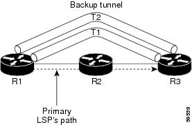
In this figure, there are three routers: R1, R2, and R3. At R1, two NNHOP backup tunnels (T1 and T2) go from R1 to R3 without traversing R2.
Redundancy—If R2 fails or the link from R1 to R2 fails, either backup tunnel can be used. If one backup tunnel is down, the other can be used. LSPs are assigned to backup tunnels when the LSPs are first established before a failure occurs.
Load balancing—If neither backup tunnel has enough bandwidth to back up all LSPs, both tunnels can be used. Some LSPs use one backup tunnel, while other LSPs use the other backup tunnel. The router decides the best way to fit the LSPs onto the backup tunnels.
Backup Tunnel Selection Procedure
When an LSP is signaled, each node along the LSP path that provides FRR protection for the LSP selects a backup tunnel for the LSP to use if either of the following events occurs:
By having the node select the backup tunnel for an LSP before a failure occurs, the LSP can be rerouted onto the backup tunnel quickly if there is a failure.
For an LSP to be mapped to a backup tunnel, all of the following conditions must exist:
- The LSP is protected by FRR; that is, the LSP is configured with the fast-reroute command.
- The backup tunnel is up.
- The backup tunnel is configured to have an IP address which is typically a loopback address.
- The backup tunnel is configured to protect this LSP’s outgoing interface; that is, the interface is configured with the mpls traffic-eng backup-path command.
- The backup tunnel does not traverse the LSP’s protected interface.
- The backup tunnel terminates at the LSP’s NHOP or NNHOP. If it is an NNHOP tunnel, it does not traverse the LSP’s NHOP.
- The bandwidth protection requirements and constraints, if any, for the LSP and backup tunnel are met. For information about bandwidth protection considerations, see the “Bandwidth Protection”.
Bandwidth Protection
A backup tunnel can be configured to protect two types of backup bandwidth:
- Limited backup bandwidth—A backup tunnel provides bandwidth protection. The sum of the bandwidth of all LSPs using this backup tunnel cannot exceed the backup tunnel’s backup bandwidth. When you assign LSPs to this type of backup tunnel, sufficient backup bandwidth must exist.
- Unlimited backup bandwidth—The backup tunnel does not provide any bandwidth protection (that is, best-effort protection exists). There is no limit to the amount of bandwidth used by the LSPs that are mapped to this backup tunnel. LSPs that allocate zero bandwidth can use only backup tunnels that have unlimited backup bandwidth.
Load Balancing on Limited-Bandwidth Backup Tunnels
There may be more than one backup tunnel that has sufficient backup bandwidth to protect a given LSP. In this case, the router chooses the one that has the least amount of backup bandwidth available. This algorithm limits fragmentation, maintaining the largest amount of backup bandwidth available.
Specifying limited backup bandwidth does not guarantee bandwidth protection if there is a link or node failure. For example, the set of NHOP and NNHOP backup tunnels that gets triggered when an interface fails may all share some link on the network topology, and this link may not have sufficient bandwidth to support all LSPs using this set of backup tunnels.
In Figure 18-5, both backup tunnels traverse the same links and hop. When the link between routers R1 and R4 fails, backup tunnels for primary tunnel 1 and primary tunnel 2 are triggered simultaneously. The two backup tunnels may share a link in the network.
Figure 18-5 Backup Tunnels Share a Link

In Figure 18-6, the backup tunnel for primary tunnel 1 may traverse routers R1-R2-R3-R4, and the backup tunnel for primary tunnel 2 might traverse routers R4-R2-R3-R1. In this case, the link R2-R3 might get overloaded if R1-R4 fails.

Load Balancing on Unlimited-Bandwidth Backup Tunnels
More than one backup tunnel, each having unlimited backup bandwidth, can protect a given interface. In this case, when choosing a backup tunnel for a given LSP, the router chooses the backup tunnel that has the least amount of backup bandwidth in use. This algorithm evenly distributes the LSPs across backup tunnels based on an LSP’s bandwidth. If an LSP is requesting zero bandwidth, the router chooses the backup tunnel that is protecting the fewest LSPs.
Pool Type and Backup Tunnels
By default, a backup tunnel provides protection for LSPs that allocate from any global pool. However, a backup tunnel can be configured to protect only LSPs that use global-pool bandwidth.
Tunnel Selection Priorities
This section includes the following topics:
- NHOP Versus NNHOP Backup Tunnels, page 18-281
- Promotion, page 18-282
- Backup Protection Preemption Algorithms, page 18-282
NHOP Versus NNHOP Backup Tunnels
More than one backup tunnel can protect a given LSP, where one backup tunnel terminates at the LSP’s NNHOP, and the other terminates at the LSP’s NHOP. In this case, the router chooses the backup tunnel that terminates at the NNHOP (FRR prefers NNHOP over NHOP backup tunnels).
Table 18-1 lists the tunnel selection priorities. The first choice is an NNHOP backup tunnel that acquires its bandwidth from a global pool and has limited bandwidth. If there is no such backup tunnel, the next choice (2) is a next-next hop backup tunnel that acquires a limited amount of bandwidth from any pool. The preferences go from 1 (best) to 8 (worst), where choice 3 is for an NNHOP backup tunnel with an unlimited amount of global-pool bandwidth.
|
|
|
|
|
|---|---|---|---|
Figure 18-7 shows an example of the backup tunnel selection procedure based on the designated amount of global pool bandwidth currently available.

Note![]() If NHOP and NNHOP backup tunnels do not have sufficient backup bandwidth, no consideration is given to the type of data that the LSP is carrying. For example, a voice LSP may not be protected unless it is signaled before a data LSP. To prioritize the backup tunnel usage, see the “Backup Protection Preemption Algorithms”.
If NHOP and NNHOP backup tunnels do not have sufficient backup bandwidth, no consideration is given to the type of data that the LSP is carrying. For example, a voice LSP may not be protected unless it is signaled before a data LSP. To prioritize the backup tunnel usage, see the “Backup Protection Preemption Algorithms”.
Figure 18-7 Choosing from Among Multiple Backup Tunnels

In this example, an LSP requires 20 units (kilobits per second) of global pool backup bandwidth. The best backup tunnel is selected as follows:
1.![]() Backup tunnels T1 is considered first because it terminates at the NNHOP.
Backup tunnels T1 is considered first because it terminates at the NNHOP.
2.![]() Tunnel T1 is chosen because it protects LSPs using global pool bandwidth.
Tunnel T1 is chosen because it protects LSPs using global pool bandwidth.
3.![]() Tunnels T5 is not considered because it terminates at an NHOP, and therefore is less desirable than T1, which terminates at an NNHOP.
Tunnels T5 is not considered because it terminates at an NHOP, and therefore is less desirable than T1, which terminates at an NNHOP.
After a backup tunnel has been chosen for an LSP, conditions may change that will cause you to reevaluate this choice. This reevaluation, if successful, is called promotion. Such conditions are as follows:
1.![]() A new backup tunnel comes up.
A new backup tunnel comes up.
2.![]() The currently chosen backup tunnel for this LSP goes down.
The currently chosen backup tunnel for this LSP goes down.
3.![]() A backup tunnel’s available backup bandwidth increases. For example, an LSP protected by the tunnel has been reoptimized by the headend to use another path.
A backup tunnel’s available backup bandwidth increases. For example, an LSP protected by the tunnel has been reoptimized by the headend to use another path.
For cases 1 and 2, the LSP’s backup tunnel is evaluated immediately. Case 3 is addressed by periodically reevaluating LSP-to-backup tunnel mappings. By default, background reevaluation is performed every 5 minutes. You can configure this interval with the fast-reroute timers command.
Backup Protection Preemption Algorithms
When you set the bandwidth protection desired bit for an LSP, the LSP has a higher right to select backup tunnels that provide bandwidth protection and it can preempt other LSPs that do not have that bit set.
If there is insufficient backup bandwidth on NNHOP backup tunnels but not on NHOP backup tunnels, the bandwidth-protected LSP does not preempt NNHOP LSPs; it uses NHOP protection.
If multiple LSPs are using a given backup tunnel and one or more must be demoted to provide bandwidth, there are two user-configurable methods (algorithms) that the router can use to determine which LSPs are demoted:
For example, if you need ten units of backup bandwidth on a backup tunnel, you can demote one of the following:
- A single LSP using 100 units of bandwidth—Makes available more bandwidth than needed but results in wasted bandwidth.
- Ten LSPs, each using one unit of bandwidth—Results in no wasted bandwidth but affects more LSPs.
The default algorithm is to minimize the number of LSPs that are demoted. To change the algorithm to minimize the amount of bandwidth that is wasted, enter the fast-reroute backup-prot-preemption optimize-bw command.
Bandwidth Protection Considerations
Bandwidth protection can be ensured in many ways. Table 18-2 describes the advantages and disadvantages of three methods.
Cisco implementation of FRR does not mandate a particular approach, and it provides the flexibility to use any of the above approaches. However, given a range of configuration choices, be sure that the choices are constant with a particular bandwidth protection strategy.
This section includes the following topics:
- Using Backup Tunnels with Explicitly Signaled Bandwidth, page 18-283
- Protected Bandwidth Pools and the Bandwidth Pool from Which the Backup Tunnel Reserves Its Bandwidth
- Using Backup Tunnels Signaled with Zero Bandwidth, page 18-284
- Signaled Bandwidth Versus Backup Bandwidth
Using Backup Tunnels with Explicitly Signaled Bandwidth
Two bandwidth parameters must be set for a backup tunnel:
To signal bandwidth requirements of a backup tunnel, configure the bandwidth of the backup tunnel by using the bandwidth command.
To configure the backup bandwidth of the backup tunnel, use the backup-bw command.
The signaled bandwidth is used by the LSRs on the path of the backup tunnel to perform admission control and do appropriate bandwidth accounting.
The backup bandwidth is used by the point of local repair (PLR) (the headend of the backup tunnel) to decide how much primary traffic can be rerouted to this backup tunnel if there is a failure.
Both parameters need to be set to ensure proper operation. The numerical value of the signaled bandwidth and the backup bandwidth should be the same.
Protected Bandwidth Pools and the Bandwidth Pool from Which the Backup Tunnel Reserves Its Bandwidth
The bandwidth command allows you to configure the following:
- Amount of bandwidth that a backup tunnel reserves
- The DS-TE bandwidth pool from which the bandwidth needs to be reserved
Note![]() Only one pool can be selected. The backup tunnel can explicitly reserve bandwidth from the global pool.
Only one pool can be selected. The backup tunnel can explicitly reserve bandwidth from the global pool.
The backup-bw command allows you to specify the bandwidth pool to which the traffic must belong for the traffic to use this backup tunnel. Multiple pools are allowed.
There is no direct correspondence between the bandwidth pool that is protected and the bandwidth pool from which the bandwidth of the backup tunnel draws its bandwidth.
Bandwidth protection for 10 Kbps of subpool traffic on a given link can be achieved by configuring any of the following command combinations:
backup-bw sub-pool 10 global-pool unlimited
backup-bw sub-pool 10 global-pool 30
Using Backup Tunnels Signaled with Zero Bandwidth
You might use backup tunnels with zero signaled bandwidth, even when bandwidth protection is required. It might seem that if no bandwidth is explicitly reserved, no bandwidth guarantees can be provided. However, that is not necessarily true, because in the following situation, only link protection is desired and bandwidth protection is desired only for subpool traffic.
For each protected link AB with a maximum reservable subpool value of n, there might be a path from node A to node B where the difference between the maximum reservable global and the maximum reservable subpool is at least the value of n. If it is possible to find such paths for each link in the network, you can establish all the backup tunnels along such paths without any bandwidth reservations. If there is a single link failure, only one backup tunnel uses any link on its path. Because that path has at least n available bandwidth (in the global pool), assuming that marking and scheduling is configured to classify the subpool traffic into a priority queue, the subpool bandwidth is guaranteed.
This approach allows sharing of the global pool bandwidth between backup tunnels that protect independent link failures. The backup tunnels are expected to be used for only a short period of time after a failure (until the headends of affected LSPs reroute those LSPs to other paths with available subpool bandwidth). The probability of multiple unrelated link failures is very small (in the absence of node failures, which result in multiple link failures). Therefore, you can assume that link failures are in practice independent with high probability. This independent failure assumption in combination with backup tunnels signaled without explicit bandwidth reservation enables efficient bandwidth sharing that yields substantial bandwidth savings.
Backup tunnels that protect the subpool traffic do not draw bandwidth from any pool. Primary traffic that uses the global pool can use the entire global pool, and primary traffic that uses the subpool can use the entire subpool. Yet, subpool traffic has a complete bandwidth guarantee if there is a single link failure.
A similar approach can be used for node protection. However, the decision of where to put the backup tunnels is more complicated because node failures effectively result in the simultaneous failure of several links. Therefore, the backup tunnels that protect traffic traversing all affected links cannot be computed independently of each other. The backup tunnels that protect groups of links corresponding to different failures can still be computed independently of each other, which results in similar bandwidth savings.
Signaled Bandwidth Versus Backup Bandwidth
Backup bandwidth is used locally (by the router that is the headend of the backup tunnel) to determine which, and how many, primary LSPs can be rerouted on a particular backup tunnel. The router ensures that the combined bandwidth requirement of these LSPs does not exceed the backup bandwidth.
Therefore, even when the backup tunnel is signaled with zero bandwidth, you must configure the backup bandwidth with the value corresponding to the actual bandwidth requirement of the traffic protected by this backup tunnel. Unlike the case when bandwidth requirements of the backup tunnels are explicitly signaled, the value of the signaled bandwidth (which is zero) is not the same value as the backup bandwidth.
Licensing Requirements for MPLS TE Fast Reroute Link and Node Protection
Prerequisites for MPLS TE Fast Reroute Link and Node Protection
Fast reroute link and node protection feature has the following prerequisites:
Guidelines and Limitations for MPLS TE Fast Reroute Link and Node Protection
Fast reroute link and node protection has the following guidelines and limitations:
- Interfaces must use MPLS global label allocation. Labels are allocated from the label table that is unique per VDC.
- Backup tunnel headend and tailend routers must implement FRR as described in draft-pan-rsvp-fastreroute-00.txt.
- Backup tunnels are not protected. If an LSP is actively using a backup tunnel and the backup tunnel fails, the LSP is torn down.
- LSPs that are actively using backup tunnels are not considered for promotion. If an LSP is actively using a backup tunnel and a better backup tunnel becomes available, the active LSP is not switched to the better backup tunnel.
- You cannot enable FRR Hellos on a router that also has Resource Reservation Protocol (RSVP) Graceful Restart enabled.
- You cannot enable primary one-hop autotunnels, backup autotunnels, or autotunnel mesh groups on a router that is also configured with stateful switchover (SSO) redundancy. This restriction does not prevent an MPLS TE tunnel that is automatically configured by TE autotunnel from being successfully recovered by any midpoint router along the LSP’s path if the router experiences an SSO switchover.
- MPLS TE LSPs that are fast reroutable cannot be successfully recovered if the LSPs are FRR active and the Point of Local Repair (PLR) router experiences an SSO.
- When SSO (stateful switchover) occurs on a router, the switchover process must complete before FRR (fast reroute) can complete successfully. In a testing environment, allow approximately 2 minutes for TE SSO recovery to complete before manually triggering FRR. To check the TE SSO status, use the show ip rsvp high-availability summary command. Note the status of the HA state field as follows:
–![]() When SSO is in the process of completing, this field displays as Recovering.
When SSO is in the process of completing, this field displays as Recovering.
–![]() When the SSO process has completed, this field displays as Active.
When the SSO process has completed, this field displays as Active.
Configuring MPLS TE Fast Reroute Link and Node Protection
This section includes the following topics:
- Enabling Fast Reroute on LSPs, page 18-287
- Creating a Backup Tunnel to the Next Hop or to the Next-Next Hop, page 18-287
- Assigning Backup Tunnels to a Protected Interface, page 18-289
- Associating Backup Bandwidth and Pool Type with a Backup Tunnel, page 18-290
- Configuring Backup Bandwidth Protection, page 18-291
Enabling Fast Reroute on LSPs
LSPs can use backup tunnels only if they have been configured as fast reroutable. You can enable fast reroute on LSPs by entering commands at the headend of each LSP.
Note![]() This procedure is required for configuring fast reroute link and node protection.
This procedure is required for configuring fast reroute link and node protection.
Prerequisites
You must have the MPLS TE feature enabled (see the “Configuring MPLS TE”).
Ensure that you are in the correct VDC (or use the switchto vdc command).
SUMMARY STEPS
DETAILED STEPS
|
|
|
|
|---|---|---|
Enters interface configuration mode for the specified tunnel. |
||
Enables an MPLS TE tunnel to use an established backup tunnel if there is a link or node failure. |
Creating a Backup Tunnel to the Next Hop or to the Next-Next Hop
Creating a backup tunnel is basically no different from creating any other tunnel. To create a backup tunnel to the next hop or to the next-next hop, enter commands on the node that will be the headend of the backup tunnel (the node whose downstream link or the node might fail). The node on which you enter these commands must be a supported platform.
Note![]() This procedure is required for configuring fast reroute link and node protection.
This procedure is required for configuring fast reroute link and node protection.
Prerequisites
You must have the MPLS TE feature enabled (see the “Configuring MPLS TE”).
Ensure that you are in the correct VDC (or use the switchto vdc command).
SUMMARY STEPS
2.![]() mpls traffic-eng configuration
mpls traffic-eng configuration
3.![]() explicit-path { identifier id | name name }
explicit-path { identifier id | name name }
7.![]() ip unnumbered interface-type interface-number
ip unnumbered interface-type interface-number
9.![]() path-option [ protect ] preference-number { dynamic | explicit { identifier id | name name} [ verbatim ]} [ lockdown ] [ bandwidth kbps] [ attributes listname]
path-option [ protect ] preference-number { dynamic | explicit { identifier id | name name} [ verbatim ]} [ lockdown ] [ bandwidth kbps] [ attributes listname]
DETAILED STEPS
Assigning Backup Tunnels to a Protected Interface
You can assign one or more backup tunnels to a protected interface by entering the commands on the node that will be the headend of the backup tunnel (the node whose downstream link or node might fail). The node on which you enter these commands must be a supported platform.
Note![]() This procedure is required for configuring fast reroute link and node protection.
This procedure is required for configuring fast reroute link and node protection.
Note![]() You must configure the interface to have an IP address and enable the MPLS TE tunnel feature.
You must configure the interface to have an IP address and enable the MPLS TE tunnel feature.
Prerequisites
You must have the MPLS TE feature enabled (see the “Configuring MPLS TE”).
Ensure that you are in the correct VDC (or use the switchto vdc command).
SUMMARY STEPS
DETAILED STEPS
Associating Backup Bandwidth and Pool Type with a Backup Tunnel
You can associate the backup bandwidth with a backup tunnel and designate the type of LSP that can use a backup tunnel.
Note![]() You can use this optional procedure to configure fast reroute link and node protection.
You can use this optional procedure to configure fast reroute link and node protection.
Prerequisites
You must have the MPLS TE feature enabled (see the “Configuring MPLS TE”).
Ensure that you are in the correct VDC (or use the switchto vdc command).
SUMMARY STEPS
DETAILED STEPS
|
|
|
|
|---|---|---|
Enters interface configuration mode for the specified tunnel. |
||
Configuring Backup Bandwidth Protection
You can configure backup bandwidth protection.
Note![]() You can use this optional procedure to configure fast reroute link and node protection.
You can use this optional procedure to configure fast reroute link and node protection.
Prerequisites
You must have the MPLS TE feature enabled (see the “Configuring MPLS TE”).
Ensure that you are in the correct VDC (or use the switchto vdc command).
SUMMARY STEPS
2.![]() mpls traffic-eng configuration
mpls traffic-eng configuration
DETAILED STEPS
Verifying the MPLS TE Fast Reroute Link and Node Protection Configuration
To determine if FRR has been configured correctly, enter the show mpls traffic-eng tunnels brief command and the show ip rsvp sender detail command. If you created LSPs and performed the required configuration tasks but do not have operational backup tunnels (that is, the backup tunnels are not up or the LSPs are not associated with those backup tunnels), enter the show mpls traffic-eng tunnel fast-reroute command.
The following example shows how to verify that the backup tunnels are up:
The following example shows how to verify that the LSPs are protected by the appropriate backup tunnels. The output was when the command was entered at the PLR before a failure.
The following example shows how to verify that MPLS TE FRR node protection has been enabled and that a certain type of LSP can use a backup tunnel.
Note![]() Enter the clear ip rsvp hello instance counters command to verify the following:
Enter the clear ip rsvp hello instance counters command to verify the following:
- MPLS TE FRR node protection has been enabled.
- A certain type of LSP can use a backup tunnel.
If LDP is not enabled, separate prefix items are not shown because all prefixes then use a single rewrite. To confirm that a particular IP prefix is FRR protected, even though it is not shown in this display, enter it within the show mpls forwarding-table ip-address detail command. The final line of the display will tell whether that prefix is protected:
The following example shows how to verify that the fast reroute backup is configured.
Enter the command on the router where the backup tunnels originate.
Src 10.55.55.55,, Dest 10.7.7.7, Instance 1
The following example shows how to display the LSPs that are protected.
Note![]() Enter the clear ip rsvp hello instance counters command to verify the following:
Enter the clear ip rsvp hello instance counters command to verify the following:
- MPLS TE FRR node protection has been enabled.
- A certain type of LSP can use a backup tunnel.
The output was entered at the headend of a primary LSP. Entering the command at the headend of the primary LSP shows the status of FRR (local protection) at each hop that this LSP traverses. The per-hop information is collected in the Record Route Object (RRO) that travels with the Resv message from the tail to the head.
Note the following about the primary LSP:
- It has protection that uses a NHOP backup tunnel at its first hop.
- It has protection and is actively using an NHOP backup tunnel at its second hop.
- It has no local protection at its third hop.
The RRO display shows the following information for each hop:
- Whether local protection is available (that is, whether the LSP has selected a backup tunnel).
- Whether local protection is in use (that is, whether the LSP is currently using its selected backup tunnel).
- Whether the selected backup tunnel is an NHOP or NNHOP backup tunnel.
- Whether the backup tunnel used at this hop provides bandwidth protection.
Configuration Examples of MPLS TE Fast Reroute Link and Node Protection
This section includes the following topics:
- Example: Enabling Fast Reroute for all Tunnels, page 18-296
- Example: Creating an NHOP Backup Tunnel, page 18-297
- Example: Creating an NNHOP Backup Tunnel, page 18-297
- Example: Assigning Backup Tunnels to a Protected Interface, page 18-297
- Example: Associating the Backup Bandwidth and Pool Type with Backup Tunnels, page 18-298
- Example: Configuring Backup Bandwidth Protection, page 18-298
- Example: Configuring RSVP Hello, page 18-298
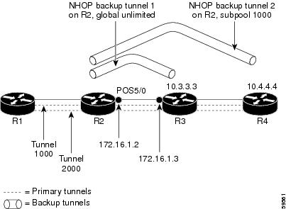
The examples relate to Figure 18-8.
Example: Enabling Fast Reroute for all Tunnels
The following example shows how to enable fast reroute for all tunnels.
On router R1, enter interface configuration mode for each tunnel to be protected (Tunnel 1000 and Tunnel 2000). Enable these tunnels to use a backup tunnel in case of a link or node failure along their paths.
Tunnel 1000 uses 10 units of bandwidth from the subpool.
Tunnel 2000 uses 5 units of bandwidth from the global pool. The bandwidth protection desired bit has been set by specifying bw-prot in the fast-reroute command.
Example: Creating an NHOP Backup Tunnel
The following example shows how to create an NHOP backup tunnel.
On router R2, create an NHOP backup tunnel to R3. This backup tunnel should avoid using the link 172.1.1.2.
Example: Creating an NNHOP Backup Tunnel
The following example shows how to create an NNHOP backup tunnel.
On router R2, create an NNHOP backup tunnel to R4. This backup tunnel should avoid R3.
Example: Assigning Backup Tunnels to a Protected Interface
The following example shows how to assign backup tunnels to a protected interface.
On router R2, associate both backup tunnels with interface Ethernet 5/0:
Example: Associating the Backup Bandwidth and Pool Type with Backup Tunnels
The following example shows how to associate the backup bandwidth and pool with backup tunnels.
Backup tunnel 1 is to be used only by LSPs that take their bandwidth from the global pool. It does not provide bandwidth protection. Backup tunnel 2 is to be used only by LSPs that take their bandwidth from the subpool. Backup tunnel 2 provides bandwidth protection for up to 1000 units.
Example: Configuring Backup Bandwidth Protection
The following example shows how to configure backup bandwidth protection.
Note![]() This global configuration is required only to change the backup protection preemption algorithm from minimizing the number of LSPs that are demoted to minimizing the amount of bandwidth that is wasted.
This global configuration is required only to change the backup protection preemption algorithm from minimizing the number of LSPs that are demoted to minimizing the amount of bandwidth that is wasted.
Example: Configuring RSVP Hello
Hello must be configured both globally on the router and on the specific interface on which you need FRR protection. To configure Hello, use the following configuration commands:
- ip rsvp signalling hello (configuration)—Enables Hello globally on the router.
- ip rsvp signalling hello (interface)—Enables Hello on an interface where you need FRR protection.
The following configuration commands are optional:
- ip rsvp signalling hello dscp —Sets the differentiated services code point (DSCP) value that is in the IP header of the Hello message.
- ip rsvp signalling hello refresh misses —Specifies how many acknowledgments that a node can miss in a row before the node considers that communication with its neighbor is down.
- ip rsvp signalling hello refresh interval —Configures the Hello request interval.
- ip rsvp signalling hello statistics —Enables Hello statistics on the router.
For configuration examples, see the Hello command descriptions in the “Command Reference” section of MPLS Traffic Engineering (TE): Link and Node Protection, with RSVP Hellos Support.
Troubleshooting Tips
This section provides the following troubleshooting information:
- LSPs Do Not Become Active; They Remain Ready, page 18-299
- Primary Tunnel Does Not Select Backup Tunnel That Is Up, page 18-299
- Enhanced RSVP Commands Display Useful Information, page 18-300
- RSVP Hello Detects When a Neighboring Node Is Not Reachable, page 18-300
- Hello Instances Have Not Been Created, page 18-300
- “No entry at index” (error may self-correct, RRO may not yet have propagated from downstream node of interest)” Error Message is Displayed at the Point of Local Repair, page 18-300
- “Couldn’t get rsbs” (error may self-correct when Resv arrives)” Error Message is Displayed at the Point of Local Repair (PLR), page 18-301
LSPs Do Not Become Active; They Remain Ready
At a PLR, LSPs transition from Ready to Active if one of the following events occurs:
- Primary interface goes down—If the primary interface (LSP’s outbound interface) goes down and the LSP is ready to use a backup tunnel, the LSP transitions to the active state causing its data to flow over the backup tunnel. On some platforms and interface types, there is a fast interface-down logic that detects this event very quickly. On other platforms where this logic does not exist, detection time is slower. On such platforms, you might enable BFD.
- Hellos detect next hop is down—If Hellos are enabled on the primary interface (LSP’s outbound interface), and the LSP’s next hop is no longer reachable, the next hop is declared down. This event will cause the LSP to begin actively using its backup tunnel. Notice that a next hop is declared down even if the primary interface does not go down. For example, if the next hop stops responding due to a reboot or a software or hardware problem, Hellos trigger the LSPs using this next hop to switch to their backup tunnels. Hellos can also help trigger FRR on interfaces such as Gigabit Ethernet where the interface remains up but is unusable (due to a lack of link-layer liveness detection mechanisms).
Primary Tunnel Does Not Select Backup Tunnel That Is Up
If a backup tunnel is up, but it is not selected as a backup tunnel by the primary tunnel (LSP), enter the following commands for the backup tunnel:
Note![]() If you change the status of a backup tunnel, the backup tunnel selection algorithm is rerun for the backup tunnel. LSPs that have currently selected (ready to use) that backup tunnels are disassociated from it, and then reassociated with that backup tunnel or another backup tunnel, which is generally harmless and usually results in mapping the same LSPs to that backup tunnel. However, if any LSPs are actively using that backup tunnel, shutting down the backup tunnel tears down those LSPs.
If you change the status of a backup tunnel, the backup tunnel selection algorithm is rerun for the backup tunnel. LSPs that have currently selected (ready to use) that backup tunnels are disassociated from it, and then reassociated with that backup tunnel or another backup tunnel, which is generally harmless and usually results in mapping the same LSPs to that backup tunnel. However, if any LSPs are actively using that backup tunnel, shutting down the backup tunnel tears down those LSPs.
Enhanced RSVP Commands Display Useful Information
The following RSVP commands have been enhanced to display information that can be helpful when you are examining the FRR state or troubleshooting FRR:
- show ip rsvp request —Displays the upstream reservation state (information that is related to the Resv messages that this node will send upstream).
- show ip rsvp reservation —Displays information about Resv messages received.
- show ip rsvp sender —Displays information about path messages being received.
These commands show the control plane state; they do not show the data state. They show information about RSVP messages (Path and Resv) used to signal LSPs. For information about the data packets being forwarded along LSPs, use the show mpls forwarding command.
RSVP Hello Detects When a Neighboring Node Is Not Reachable
The RSVP Hello feature enables RSVP nodes to detect when a neighboring node is not reachable. Use this feature when notification of link-layer failures is not available and unnumbered links are not used or when the failure detection mechanisms provided by the link layer are not sufficient for timely node failure detection. You must configure Hello both globally on the router and on the specific interface to be operational.
Hello Instances Have Not Been Created
If Hello instances have not been created, do the following:
- Determine if RSVP Hello has been enabled globally on the router. Enter the ip rsvp signalling hello (configuration) command.
- Determine if RSVP Hello has been enabled on an interface that the LSPs traverse. Enter the ip rsvp signalling hello (interface) command.
Verify that at least one LSP has a backup tunnel by displaying the output of the show ip rsvp sender command. A value of “Ready” indicates that a backup tunnel has been selected.
“No entry at index” (error may self-correct, RRO may not yet have propagated from downstream node of interest)” Error Message is Displayed at the Point of Local Repair
FRR relies on a RRO in Resv messages arriving from downstream. Routers that receive path messages with the SESSION_ATTRIBUTE bit indicating that the LSP is fast-reroutable should include an RRO in the corresponding Resv messages.
If an LSP is configured for FRR, but the Resv arriving from a downstream router contains an incomplete RRO, the “No entry at index (error may self-correct, RRO may not yet have propagated from downstream node of interest)” message is displayed. An incomplete RRO is when the NHOP or the NNHOP did not include an entry in the RRO.
This error typically means that backup tunnels to the NHOP or the NNHOP cannot be selected for this LSP because there is insufficient information about the NHOP or NNHOP due to a missing RRO entry.
There are valid circumstances in which this situation occurs temporarily and the problem self corrects. If subsequent Resv messages arrive with a complete RRO, you should ignore the error message.
To determine whether the error has been corrected, display the RRO in Resv messages by entering the clear ip rsvp hello instance counters command. Use an output filter keyword to display only the LSP of interest.
“Couldn’t get rsbs” (error may self-correct when Resv arrives)” Error Message is Displayed at the Point of Local Repair (PLR)
The PLR cannot select a backup tunnel for an LSP until a Resv message has arrived from downstream. When this error occurs, it typically means that something is wrong. For example, no reservation exists for this LSP.
There are valid circumstances in which this error message is displayed and there is no need for concern. One such circumstance is when an LSP experiences a change before any Resv message has arrived from downstream. Changes can cause a PLR to try to select a backup tunnel for an LSP, and the selection will fail (causing this error message) if no Resv message has arrived for this LSP.
Additional References for MPLS TE Fast Reroute Link and Node Protection
The following sections provide references related to the fast reroute link and node protection feature.
Related Documents
|
|
|
|---|---|
MPLS TE: Link and Node Protection, with RSVP Hellos Support (with Fast Tunnel Interface Down Detection) |
|
MIBs
|
|
|
|---|---|
To locate and download MIBs for selected platforms, Cisco NX-OS releases, and feature sets, use Cisco MIB Locator found at the following URL: |
Feature History for MPLS TE Fast Reroute Link and Node Protection
Table 18-3 lists the release history for this feature.
|
|
|
|
|---|---|---|
 Feedback