Prerequisites for PBR Support for the VXLAN BGP EVPN Fabric
- A Cisco Nexus 7000 Series switch with an F3 or M3 line card.
- Understand how VXLAN BGP EVPN works.
- Enable VXLAN BGP EVPN configurations on the leaf and spine switches.
The documentation set for this product strives to use bias-free language. For the purposes of this documentation set, bias-free is defined as language that does not imply discrimination based on age, disability, gender, racial identity, ethnic identity, sexual orientation, socioeconomic status, and intersectionality. Exceptions may be present in the documentation due to language that is hardcoded in the user interfaces of the product software, language used based on RFP documentation, or language that is used by a referenced third-party product. Learn more about how Cisco is using Inclusive Language.
Policy-based routing (PBR) support is provided for the Virtual eXtensible Local Area Network (VXLAN) Border Gateway Protocol (BGP) Ethernet VPN (EVPN) fabric. PBR allows you to configure a defined policy for IPv4 and IPv6 traffic flows, lessening reliance on routes derived from routing protocols. All packets received on a PBR enabled interface are passed through enhanced packet filters or route maps. The route maps dictate the policy, determining where to forward packets. PBR configurations have to be enabled on relevant Top of Rack (ToR) or leaf switches, and spine switches in the VXLAN BGP EVPN fabric. For more information on PBR, see Cisco Nexus 7000 Series NX-OS Unicast Routing Configuration Guide.
This chapter contains the following sections:
This feature is not supported on port channels, channel members, Virtual Station Interface (VSI) trunk ports, and tunnel interfaces.
Equal-Cost Multipath (ECMP) for IPv4/IPv6 adjacencies and BGP EVPN tunnel adjacencies are not supported at the same time.
Virtual routing and forwarding (VRF) leak scenarios require that VRF context definitions should be consistent across all participating VTEPs.
A sample workflow and PBR rules on ToR switches:
 Note |
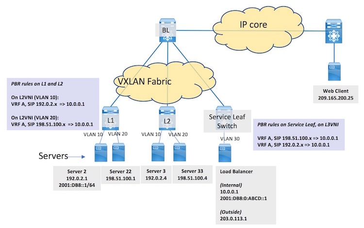
In the figure, SIP refers to the source IP address. |
Servers, virtual machines (VMs) and containers specific to a service are attached to ToR or leaf switches spread across the fabric (Server 2 and Server 22 attached to L1, and Server 3 and Server 33 attached to L2). The load balancer is attached to a service leaf switch at the right. A web client outside the fabric requests the service. When the request reaches the load balancer through the border leaf switch BL and the service leaf switch, it forwards the service request to an appropriate server (Server 2). PBR configurations should be enabled on L1, L2, and the service leaf switch. The workflow:
The web client (IP address 209.165.200.25) sends a request for a specific service available in the servers attached to L1 and L2. The destination IP address in the packets is 203.0.113.1, the load balancer’s IP address. This IP address is advertised to clients outside the fabric. The request reaches BL.
BL knows from the BGP EVPN control plane that the load balancer is attached to the service leaf switch. BL VXLAN encapsulates the packets and forwards the request to the service leaf switch.
The service leaf switch receives it, VXLAN decapsulates the packets and sends the traffic to the load balancer.
The load balancer uses a unique IP address 10.0.0.1 (or 2001:DB8:0:ABCD::1 for IPv6) when load balancing traffic to one of the servers hosting the service. The load balancer decides to forward the request to Server 2. In the packet header, the load balancer updates the destination IP address to 192.0.2.1 (or 2001:DB8::1), while the source IP address remains 209.165.200.25 (or a designated IPv6 address), and forwards it to the service leaf switch. The service leaf switch sends the traffic over the VXLAN BGP EVPN fabric towards L1. L1 decapsulates the VXLAN header and forwards the original packet to Server 2.
Server 2 responds to the service request. The source IP address is 192.0.2.1 or 2001:DB8::1/64 (Server 2’s IP address), and the destination IP address remains 209.165.200.25. The response is sent to L1.
On L1, normal packet forwarding determines that the destination address is behind the border leaf switch. However, PBR policy is applied on the interface on which the server is attached such that the packet is forwarded to the service leaf switch instead of the border leaf switch.
On the service leaf switch, after VXLAN decapsulation, normal packet forwarding determines that the destination address 209.165.200.25 is behind the border leaf switch. However, PBR policy is applied on the Layer-3 VNI interface such that the packet is forwarded to the service leaf switch instead of the border leaf switch.
The service leaf switch forwards it to BL, which forwards the service response to the web client.
For server traffic (with source IP address 192.0.2.x, belonging to VLAN 10, VRF A, and Layer 2 virtual network identifier [VNI] 1000) received on interface BDI10, send traffic to 10.0.0.1 (or 2001:DB8:0:ABCD::1).
For server traffic (with source IP address 198.51.100.x, belonging to VLAN 20, VRF A and Layer 2 VNI 2000), send traffic to 10.0.0.1 (or 2001:DB8:0:ABCD::1).
For server traffic (with source IP address 192.0.2.x or 198.51.100.x, belonging to VRF A, and Layer 3 VNI 50000) received on the PBR interface, send traffic to 10.0.0.1 (or 2001:DB8:0:ABCD::1).
Note |
Type the switch# configure terminal command to enter global configuration mode (config)# |
Step 1 On L1, configure PBR and create an access list:
(config)# feature pbr
          ip access-list 1
            permit ip 192.0.2.1 0.0.0.255 host 10.0.0.1
            exit
          ipv6 access list vlan102-112
          10 permit ipv6 2001:DB8::1/64 2001:DB8:0:ABCD::1/64
As per PBR rules, traffic from 192.0.2.1 or 2001:DB8::1/64 (Server 2's IP address) is sent to 10.0.0.1 or 2001:DB8:0:ABCD::1/64 (the load balancer's IP address), respectively.
Step 2 On L1, create a route map and set rules:
(config)# route-map equal-access permit 10
            match ip address 1
            set ip vrf A next-hop 10.0.0.1
(config)# route-map equal-access-v6 permit 10
             match ipv6 address vlan102-112
             set ip vrf A next-hop 2001:DB8:0:ABCD::1
An IPv4 route map policy equal-access, and an IPv6 route map policy equal-access-v6 are created.
The set ip vrf command (introduced in this feature) resolves the next hop IP address for VRF A, for the IPv4 and IPv6 route map policies.
Step 3 Enable the route map policy on the BDI:
Note |
Policy routing is specified on the interface (bdi10) that receives the packets, and not on the interface from which the packets are sent. |
(config)# interface bdi10
            vrf member A
            ip policy route-map equal-access
            ipv6 policy route-map equal-access-v6
Step 4 The configurations are relevant for BDI10. Similarly, enable PBR configurations for BDI 20 on L1.
Step 5 Enable PBR configurations on BDI10 and BDI20 on L2 and service leaf switch.
Verify PBR configurations on L1:
PBR route map policy equal-access is implemented on BDI10:
L1# show running-configuration interface Bdi10

…
interface Bdi10
  no shutdown
  vrf member A
  no ip redirects
  ip address 192.0.2.200/24
  fabric forwarding mode anycast-gateway
  ip policy route-map equal-access
  ipv6 policy route-map equal-access-v6
Route map policy configuration details:
L1# show running-configuration rpm

feature pbr
route-map equal-access permit 10
   match ip address 1
   set ip next-hop 10.0.0.1

route-map equal-access-v6 permit 10
   match ipv6 address vlan102-112
   set ipv6 next-hop 2001:DB8:0:ABCD::1

interface Bdi100
   ip policy route-map equal-access
   ipv6 policy route-map equal-access-v6
This table lists the release history for this feature.
|
Feature Name |
Release |
Feature Information |
|---|---|---|
|
PBR support for the VXLAN BGP EVPN fabric |
8.2(1) |
This feature was introduced. |
 Feedback