Only
configurations relevant to the VXLAN BGP EVPN and OTV Interoperation feature
are noted here. If VXLAN BGP EVPN fabric configurations are not enabled on the
fabric’s leaf and spine switches, enable them. See the "Configuring the VXLAN
BGP EVPN" chapter, or
Cisco Programmable Fabric with
VXLAN BGP EVPN Configuration Guide.
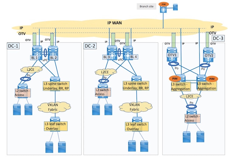
VXLAN BGP EVPN and
OTV configurations should be configured on a single box, the border leaf vPC
switch pair. BL1 and BL2 configurations on DC-1:
Step 1
Configure tunnel
stitching in the VXLAN overlay
The VXLAN BGP
EVPN configurations are documented in the
Configuring
VXLAN BGP EVPN chapter. Only VXLAN configurations required for the VXLAN
and OTV interoperation for the one-box solution are given.
BL1(config)# feature nve
             vni 40000
             system bridge-domain 2500-3500
             bridge-domain 3500
                 member vni 40000
                 exit
             interface nve1
                source-interface loopback0
                tunnel-stitching enable
                member vni 40000
                  no suppress-arp
                  mcast-group 239.1.1.65
Step 2
Configure the
VXLAN overlay loopback interface
BL1(config)# interface loopback0
                ip address 209.165.200.25/32
                ip address 203.0.113.1/32 secondary
Step 3
Configure tunnel
switching in the OTV overlay
BL1(config)# feature otv
             otv site-vni 40000
             interface Overlay1
                 otv join-interface Ethernet5/5
                 otv extend-vni 10000, 20000
                 otv vni mapping 10000, 20000, 30000 to vlan 1000, 2000, 3000
                 otv use-adjacency-server 10.0.0.1 unicast-only
                 no otv suppress-arp-nd
                 otv tunnel-stitch
                 no shutdown
                 exit
             otv site-identifier 0000.0000.000A
             otv encapsulation-format ip gre
-
The
otv
site-vni command enables the OTV site specific VNI. This VNI
should not be extended over any overlay interface and should be operationally
up before it can be configured as the OTV site VNI. At least one interface
should be present where the VNI is up. On a VXLAN + OTV pod, the VNI can be
configured under the NVE interface. If the
otv
site-vlan configuration is enabled, then you need to remove it
before configuring the
otv
site-vni command.
-
The
otv
tunnel-stitch command is the OTV command for connecting VXLAN and
OTV tunnels.
-
For OTV
overlays, only Generic Routing Encapsulation (GRE) encapsulation is supported
for the 8.2(1) release.

Note
|
You should enable ARP proxy under the OTV overlay and ARP
suppression under the VXLAN overlay at the same time or you should disable both
the functions.
|
Step 4
Configure the
VXLAN and OTV tunnel stitching configurations on BL2.
Step 5
Configure vPC
function on BL1 and BL2
vPC Peer 1 (BL1)
configuration
BL1(config)# interface Bdi3500
               no shutdown
               vrf member cust1
               no ip redirects
               ip address 198.51.100.20/24
               ip address 198.51.100.1/24 secondary anycast-primary
               ipv6 address 2001:DB8:1::1/64
               no ipv6 redirects
               fabric forwarding mode anycast-gateway
vPC Peer 2 (BL2)
configuration
BL2(config)# interface Bdi3500
               no shutdown
               vrf member cust1
               no ip redirects
               ip address 198.51.100.30/24
               ip address 198.51.100.1/24 secondary anycast-primary
               ipv6 address 2001:DB8:1::1/64
               no ipv6 redirects
               fabric forwarding mode anycast-gateway
-
The unique,
primary gateway IP address (198.51.100.20 for vPC peer 1, and 198.51.100.30 for
vPC peer 2 switches) will be used for sending ARP requests over OTV. The
common, secondary anycast gateway IP address (198.51.100.1) will be used for
sending ARP requests on the VXLAN side.
Step 6
The
configurations are for DC-1. Similarly, configure for DC-2 too.

 Feedback