Catena Configuration Process

Catena Configuration Process

You can configure Cisco Nexus devices such that packets can be redirected through multiple devices using Catena.

To configure catena:

  1. Enable catena.

  2. Create a port group.

  3. Create a VLAN group.

  4. Create a device group.

  5. Create an IP ACL.

  6. Create a Port ACL.

  7. Create a catena instance.

Enabling or Disabling the Catena Solution

By default, catena is disabled on the Cisco NX-OS device. You must explicitly enable catena to configure and verify authentication commands.

Before you begin

Ensure that you have installed the network services license. When configuring a catena instance in routed mode, you must enable PBR and IP SLA features.

SUMMARY STEPS

  1. configure terminal
  2. [no] feature catena enabling or disabling
  3. (Optional) copy running-config startup-config

DETAILED STEPS

  Command or Action Purpose
Step 1

configure terminal

Example:

switch# configure terminal
switch(config)#

Enters global configuration mode.

Step 2

[no] feature catena enabling or disabling

Example:

switch(config)# feature catena

Enables catena. Use the no form of this command to disable catena.

Note 
When you disable catena, all related configurations are automatically discarded.
Step 3

(Optional) copy running-config startup-config

Example:

switch(config)# copy running-config startup-config
(Optional)

Copies the running configuration to the start up configuration.

Configuring a Port Group

A port group consists of a set of interfaces. You must configure port groups for both routed and transparent modes.


Note

If the egress port has multiple ports, then traffic is load balanced.

SUMMARY STEPS

  1. configure terminal
  2. catena port-group port-group-name
  3. interface interface-reference
  4. (Optional) copy running-config startup-config

DETAILED STEPS

  Command or Action Purpose
Step 1

configure terminal

Example:

switch# configure terminal
switch(config)#

Enters global configuration mode.

Step 2

catena port-group port-group-name

Example:

switch(config)# catena port-group pg1

Creates a catena port group, and enters port group configuration mode.

Step 3

interface interface-reference

Example:

switch(config-port-group)# interface Eth 2/2
switch(config-port-group)# interface Eth 2/3
switch(config-port-group)# interface Eth 2/4
switch(config-port-group)# interface Eth 2/5

Configures active catena ports, with link-based tracking enabled by default.

Step 4

(Optional) copy running-config startup-config

Example:

switch(config)# copy running-config startup-config
(Optional)

Copies the running configuration to the startup configuration.

Configuring a VLAN Group

To create and configure a VLAN group:

SUMMARY STEPS

  1. configure terminal
  2. catena vlan-group vlan-group-name
  3. vlan vlan-range
  4. (Optional) copy running-config startup-config

DETAILED STEPS

  Command or Action Purpose
Step 1

configure terminal

Example:

switch# configure terminal
switch(config)#

Enters global configuration mode.

Step 2

catena vlan-group vlan-group-name

Example:

switch(config)# catena vlan-group vg1

Creates a catena VLAN group, and enters VLAN configuration mode.

Step 3

vlan vlan-range

Example:

switch(config-vlan-group)# vlan 10
switch(config-vlan-group)# vlan 20
switch(config-vlan-group)# vlan 30-40
switch(config-vlan-group)# vlan 50,55

Assign a VLAN to the configured VLAN group. Repeat this step to specify all VLANs.

Step 4

(Optional) copy running-config startup-config

Example:

switch(config)# copy running-config startup-config
(Optional)

Copies the running configuration to the startup configuration.

Configuring a Device Group

A device group contains a list of node IP addresses. If you are creating a Layer 3 routed mode deployment, you must create a device group.

To create and configure a device group:


Note

If there are multiple nodes, then traffic is load balanced accordingly.

SUMMARY STEPS

  1. configure terminal
  2. catena device-group device-group-name
  3. node {ip ipv4-address | IPv6 ipv6-address }
  4. probe probe-id [control status] [host host-name] [frequency frequency-number | timeout timeout | retry-down-count down-count | retry-up-count up-count | ip ipv4-address]
  5. (Optional) vrf vrf-name
  6. (Optional) erspan-ip ipv4-address

DETAILED STEPS

  Command or Action Purpose
Step 1

configure terminal

Example:

switch# configure terminal
switch(config)#

Enters global configuration mode.

Step 2

catena device-group device-group-name

Example:

switch(config)# catena device-group s-dg-1

Creates a device group and enters the device group configuration mode.

Step 3

node {ip ipv4-address | IPv6 ipv6-address }

Example:

switch(config-device-group)# node ip 1.1.1.1
switch(config-device-group)# node ip 2.2.2.2
switch(config-device-group)# node ip 3.3.3.3

Example:

switch(config-device-group)# node ipv6 210::10:10:11
switch(config-device-group)# node ipv6 210::10:10:12

Configures a list of node IP addresses. These are the IP addresses of your appliances. Traffic is redirected to the appliances that can perform load balancing. These devices must be in active mode. In the example, node ip 1.1.1.1, node ip 2.2.2.2, and node ip 3.3.3.3 are the IP addresses of the appliances.

Step 4

probe probe-id [control status] [host host-name] [frequency frequency-number | timeout timeout | retry-down-count down-count | retry-up-count up-count | ip ipv4-address]

Example:

switch(config-device-group)# probe icmp

Configure the device group probe.

You can specify an Internet Control Message Protocol (ICMP), Transmission Control Protocol (TCP), Hypertext Transfer Protocol (HTTP), User Datagram Protocol (UDP), or Domain Name System (DNS) probe for the catena instance.

The following describe some of the keyword-argument pairs:

  • control status —Specifies the control protocol status.

  • frequency frequency-number —Specifies the time interval, in seconds, between successive probes sent to the node.

  • timeout timeout —Specifies the number of seconds to wait for the probe's response.

  • retry-down-count down-count —Specifies the consecutive number of times the probe must have failed before the node being marked as DOWN.

  • retry-up-count up-count —Specifies the consecutive number of times the probe must have succeeded before the node being marked as UP.

Step 5

(Optional) vrf vrf-name

Example:

switch(config-device-group)# vrf vrf1
(Optional)

Configures VRF for a device group.

Step 6

(Optional) erspan-ip ipv4-address

Example:

switch(config-device-group)# erspan-ip 1.1.1.1
(Optional)

Global origin IP address.

Configuring an IP ACL

Before you begin

You will need to determine the type of traffic you want to induce into the chain. For more information about access lists, see The Cisco Nexus 9000 Series NX-OS Security Configuration Guide, Release 7.x.

SUMMARY STEPS

  1. configure terminal
  2. ip access-list
    • ip access-list acl-name
    • IPv6 access-list acl-name
  3. sequence-number {permit | deny} protocol source destination

DETAILED STEPS

  Command or Action Purpose
Step 1

configure terminal

Example:

switch# configure terminal
switch(config)#

Enters global configuration mode.

Step 2

ip access-list

  • ip access-list acl-name
  • IPv6 access-list acl-name

The maximum number of characters in the acl-name argument is 64.

Step 3

sequence-number {permit | deny} protocol source destination

You can create many rules. The range for sequence-number is 1-4294967295. The permit and deny keywords support different ways of identifying traffic.

Configuring a Port ACL

Port ACLs (PACLs) are used as filters in transparent mode. They are used to segregate IP traffic for transparent mode PACL. When you enable PACL, traffic is redirected to a particular egress interface based on the access control entries (ACE).

SUMMARY STEPS

  1. configure terminal
  2. configure catena port-acl
  3. sequence-number {permit | deny} {ip source destination} |{udf udf-name value mask}

DETAILED STEPS

  Command or Action Purpose
Step 1

configure terminal

Example:

switch# configure terminal
switch(config)#

Enters global configuration mode.

Step 2

configure catena port-acl

Example:

switch(config)# catena port-acl pacl1

Creates a catena PACL and enters catena PACL configuration mode.

Step 3

sequence-number {permit | deny} {ip source destination} |{udf udf-name value mask}

Example:

switch(config)# catena port-acl Test
 10 permit udf pktoff10 0x123 0x12ab --------> Adding UDF as separate entry
20 permit ip host 1.1.1.1 any udf pktoff20 0x567 0xfff --------> Adding UDF along with IP ACE entry
30 permit ip 10.10.10.10 0.0.0.255 20.20.20.20/24 udf pktoff30 0xabcd 0xdddd
40 permit ip 100.100.100.250/28 any udf pktoff40 0x12 0xffff

You can create many rules. The range for sequence-number is 1-4294967295. The permit and deny keywords support different ways of identifying traffic.

Configuring a Catena Instance

A catena instance is a container for multiple chains. You must configure the necessary groups for ports, VLANs, or devices before starting your catena instance.

To create or delete a catena instance.

Before you begin

Enable the catena solution. See Enabling or Disabling the Catena Solution.

Configure the port group, VLAN, device group, and access control list, for the catena instance.

SUMMARY STEPS

  1. configure terminal
  2. catena instance-name
  3. chain chain-id
  4. sequence-number access-list acl-name {vlan-group | ingress-port-group iPage-name} {egress-port-group ePage-name | egress-device-group edg-name} load-balance {algo-based {src-ip | dst-ip} | ecmp | port-channel {reverse-port-group Pgname | reverse-device-group dgname | reverse-policy} [ mode mode | span ]
  5. no shut
  6. (Optional) copy running-config startup-config

DETAILED STEPS

  Command or Action Purpose
Step 1

configure terminal

Example:

switch# configure terminal
switch(config)#

Enters global configuration mode.

Step 2

catena instance-name

Example:

switch(config)# catena ins1

Creates a catena instance and enters catena instance configuration mode.

Step 3

chain chain-id

Example:

switch(config-catena-instance)# chain 10

Example:

switch(config-catena-instance)# chain 20

Creates a chain ID. A chain is a list of elements where each element corresponds to an appliance. Creating a chain also allows you to specify the number and sequence of elements, enabling traffic redirection.

The examples shows two separate chains.

Step 4

sequence-number access-list acl-name {vlan-group | ingress-port-group iPage-name} {egress-port-group ePage-name | egress-device-group edg-name} load-balance {algo-based {src-ip | dst-ip} | ecmp | port-channel {reverse-port-group Pgname | reverse-device-group dgname | reverse-policy} [ mode mode | span ]

Example:

switch(config-catena)# 10 access-list acl11 vlan-group vg1 egress-port-group pg1 mode forward

Example:

To configure SPAN support in a Catena chain:

switch(config-catena)# 10 access-list acl1 ingress-port-group pg1 egress-device-group dg2 span

Example:

switch(config-catena)# 10 access-list acl12 ingress-port-group pg1 egress-device-group s-dg-1 mode forward

Example:

switch(config-catena)# 20 access-list acl13 vlan-group vg3 egress-port-group pg1 reverse-port-group pg4 mode forward

The following describes some of the keyword-argument pairs:

  • sequence-number—Specifies the sequence number.

  • access-list acl-name—Specifies the access list.

  • vlan-group vg-name—Specifies the VLAN group.

  • ingress-port-group ipg-name—Specifies the ingress port group.

  • egress-port-group epg-name—Specifies the egress port group.

  • reverse-port-group rpg-name—Specifies the reverse port group.

  • mode fail-action mode—Specifies the device fail-action mode type (forward, bypass, or drop) for the received packets.

  • span—Specifies SPAN traffic support for Catena.

  • load-balance —Specifies the type of load balancing for catena traffic.

    • port-channel—Specifies hash based load balancing.

    • src-ip | dst-ip—Specifies TCAM based load-balancing.

  • reverse device group— Specifies the device group in the reverse direction for routed mode.

  • reverse policy—Defines the policy in the reverse direction for the PACL.

  • reverse port group—Defines the port group in the reverse direction for the VACL.

The first example describes a transparent mode (Layer 2) service chain. A Layer 2 chain requires that you create and define both a port and a VLAN group.

The second example describes a routed mode (Layer 3) chain. A Layer 3 chain requires that you create and define both a port and an egress device group.

Currently, you must configure separate instances for Layer 2 and Layer 3 modes.

A catena instance can comprise multiple chains that are independent of each other. The traffic in each chain is forwarded as defined. However, if there is an overlap between packets from different chains at the ingress port, then all the chains configured on that ingress interface will be evaluated. If a match is found on the ingress interface, then the matching chain is accepted and forwarded.

The third example shows the egress interface in the reverse direction. You must define each segment of the chain

Step 5

no shut

Example:

switch (config-catena-instance)# no shut

Enables the catena instance.

Step 6

(Optional) copy running-config startup-config

Example:

switch# copy running-config startup-config
(Optional)

Copies the running configuration to the startup configuration.

Enabling a Catena Instance

Before you begin

Check that you have completed the following:

  1. Enable the catena solution. For details, see Enabling or Disabling the Catena Solution.

  2. Configure the catena instance. For details, see Configuring a Catena Instance.

  3. You must run the following commands before enabling the catena instance in routed mode deployment:

    • feature pbr

    • feature sla sender

    • feature sla responder

SUMMARY STEPS

  1. configure terminal
  2. catena instance-name
  3. no shut

DETAILED STEPS

  Command or Action Purpose
Step 1

configure terminal

Example:

switch# configure terminal
switch(config)#

Enters global configuration mode.

Step 2

catena instance-name

Creates a catena instance and enters the catena instance configuration mode.

Step 3

no shut

Enables the catena instance.

Verifying the Catena Configuration

Displays the status and configuration for a specified catena instance.

Command

Purpose

show catena instance-name [brief]

Displays the status and configuration for a specified catena instance.

  • Use the instance-name argument to display the status and configuration for the specified instance.

  • Use the brief keyword to display the summary status and configuration information.

show running-config catena

Displays current catena running configuration.

Displaying Catena Analytics

To optimize your chaining solution, you can configure catena to display the number of packets passing through different chains for a particular instance.

Command

Purpose

show catena analytics per-acl per-node

Displays the live traffic data going through various transparent devices.
  • Use the per-acl argument to display packet counters for a particular chain.

  • Use the per-node argument to display packet counters for a particular node.

show catena analytics per-acl per-device-group device-group-name

Displays the status and configuration for a specified catena device group instance.

show catena analytics per-acl {per-catena-instance instance-name| per-chain chain-id}

Displays the status and configuration for a specified catena instance or chain.

show catena analytics per-acl per-vlan-group

Displays the number of packets per ACL per VLAN group in a catena chain (Transparent Mode).

show catena analytics per-acl per-port-group

Displays the number of packets per ACL per port group in a catena chain (Transparent Mode).

show catena analytics per-acl total

Displays the total number of packets for a particular ACL.

Configuration Examples of Catena Instances

This topic shows examples of configuring catena instances in multiple configurations.

Configuring a catena instance in transparent mode VACL:

Figure 1. Transparent Mode VACL
switch# configure terminal
switch(config)# feature catena
switch(config)# catena port-group pg1
switch(config-port-group)# interface Eth 1/2
switch(config-pg-node)# catena port-group pg2
switch(config-port-group)# interface Eth 1/4
switch(config-pg-node)# catena vlan-group vg1
switch(config-vlan-group)# vlan 10
switch(config-vlan-group)# catena vlan-group vg2
switch(config-vlan-group)# vlan 20
switch(config)# ip access-list acl1
switch(config-acl)# 10 permit ip 192.0.2.1/24 any
switch(config)# ip access-list acl2
switch(config-acl)# 10 permit ip 198.51.100.1/24 any
switch(config)# ip access-list acl3
switch(config-acl)# 10 permit ip 203.0.113.1/24 any
switch(config-acl)# exit
switch(config)# catena ins_1
switch(config-catena-instance)# chain 10
switch(config-catena)# 10 access-list acl1 vlan-group vg1 egress port-group pg1 mode forward
switch(config-catena)# 20 access-list acl1 vlan-group vg2 egress port-group pg2 mode forward
switch(config-catena)# no shutdown
switch(config-catena-)# catena ins_2
switch(config-catena-instance)# chain 10
switch(config-catena)#10 access-list acl2 vlan-group vg1 egress port-group pg1 mode forward
switch(config-catena)#20 access-list acl2 vlan-group vg1 egress port-group pg1 mode forward
switch(config-catena)# no shutdown
switch# show running-config catena
feature catena
catena vlan-group vg1
vlan 10
catena vlan-group vg2
vlan 20
catena port-group pg1
interface Eth1/2
catena port-group pg2
interface Eth1/4
catena ins_1
chain 10
10 access-list acl1 vlan-group vg1 egress-port-group pg1 mode forward
20 access-list acl1 vlan-group vg2 egress-port-group pg2 mode forward
no shutdown
catena ins_2
chain 10
10 access-list acl2 vlan-group vg1 egress-port-group pg1 mode forward
20 access-list acl2 vlan-group vg2 egress-port-group pg2 mode forward
no shutdown

Configuring a catena instance in transparent mode PACL:

switch# configure terminal
switch(config)# feature catena
switch(config)# catena port-group pg1
switch(config-port-group)# interface Eth 1/1
switch(config-pg-node)# catena port-group pg2
switch(config-port-group)# interface Eth 1/2
switch(config-pg-node)# catena port-group pg3
switch(config-port-group)# interface Eth 1/3
switch(config-pg-node)# catena port-group pg4
switch(config-port-group)# interface Eth 1/4
switch(config-pg-node)# catena port-acl acl1
switch(config-port-acl)# 10 permit ip 192.0.2.1/24 any
switch(config-port-acl)# 20 deny ip 198.51.100.1/24 any
switch(config-port-acl)# catena ins_1
switch(config-catena-instance)# chain 10
switch(config-catena)# 10 access-list acl1 ingress-port-group pg1 egress port-group pg2
mode forward
switch(config-catena)# 20 access-list acl1 ingress-port-group pg3 egress port-group pg4
mode forward
switch(config-catena)# no shutdown
switch# show running-config catena
feature catena
catena port-acl acl1
10 permit ip 192.0.2.1/24 any
20 deny ip 198.51.100.1/24 any
catena port-group pg1
interface Eth1/1
catena port-group pg2
interface Eth1/2
catena port-group pg3
interface Eth1/3
catena port-group pg4
interface Eth1/4
catena ins1
chain 10
10 access-list acl1 ingress-port-group pg1 egress-port-group pg2 mode forward
20 access-list acl1 ingress-port-group pg3 egress-port-group pg4 mode forward
no shutdown

Configuring a catena instance for TCAM-based Load Balancing:

switch# configure terminal
switch(config)# feature catena
switch(config)# catena port-group Pg1
switch(config-port-group)# interface Eth 1/2
switch(config-port-group)# interface Eth 1/3
switch(config-Page-node)# catena port-group Pg2
switch(config-port-group)# interface Eth 1/6
switch(config-Page-node)# catena vlan-group vg1
switch(config-vlan-group)# vlan 10
switch(config-vlan-group)# catena vlan-group vg2
switch(config-vlan-group)# vlan 20
switch(config)# ip access-list acl1
switch(config-acl)# 10 permit ip 192.0.2.1/24 any
switch(config)# ip access-list acl2
switch(config-acl)# 10 permit ip 198.51.100.1/24 any
switch(config)# catena ins_redirect
switch(config-catena-instance)# chain 10
switch(config-catena)# 10 access-list acl1 vlan-group vg1 egress port-group Pg1 load-balance method src-ip mode forward
switch(config-catena)# 20 access-list acl1 vlan-group vg2 egress port-group Pg2 mode forward
switch(config-catena)# no shutdown

switch# show running-config catena
feature catena
catena vlan-group vg1
vlan 10
catena vlan-group vg2
vlan 20
catena port-group Pg1
interface Eth1/2
interface Eth1/3
catena port-group Pg2
interface Eth1/6
catena ins_redirect
chain 10
10 access-list acl1 vlan-group vg1 egress-port-group Pg1 load-balance method src-ip mode forward 
20 access-list acl1 vlan-group vg2 egress-port-group Pg2 mode forward
no shutdown

Configuring a catena instance in Routed mode:

switch# configure terminal
switch(config)# feature catena
switch(config)# catena port-group Pg1
switch(config-port-group)# interface Eth 1/1
switch(config-Page-node)# catena port-group Pg2
switch(config-port-group)# interface Eth 2/1
switch(config-Page-node)# catena port-group Pg3
switch(config-port-group)# interface Eth 2/2
switch(config-Page-node)# catena device-group dg1
switch(config-device-group)# node ip 209.165.200.225
switch(config-device-group)# probe icmp
switch(config-device-group)# catena device-group dg2
switch(config-device-group)# node ip 209.165.201.1
switch(config-device-group)# probe icmp
switch(config-device-group)# catena device-group dg3
switch(config-device-group)# node ip 209.165.202.129
switch(config-device-group)# probe icmp
switch(config-device-group)# ip access-list acl1
switch(config-acl)# 10 permit ip 192.0.2.1/24 any
switch(config)# ip access-list acl2
switch(config-acl)# 10 permit ip 198.51.100.1/24 any
switch(config-acl)# ip access-list acl3
switch(config-acl)# 10 permit ip 203.0.113.1/24 any
switch(config-acl)# ip access-list acl4
switch(config-acl)# 10 permit ip 10.0.0.1/8 any
switch(config)# catena ins_1
switch(config-catena-instance)# chain 10
switch(config-catena)# 10 access-list acl1 ingress-port-group Pg1 egress-device-group dg1 mode forward
switch(config-catena)# 20 access-list acl1 ingress-port-group Pg2 egress-device-group dg2
mode forward
switch(config-catena)# 30 access-list acl1 ingress-port-group Pg3 egress-device-group dg3 mode forward
switch(config-catena)# no shutdown
switch(config-catena-instance)# catena ins_2
switch(config-catena-instance)# chain 10
switch(config-catena)# 10 access-list acl2 ingress-port-group Pg1 egress-device-group dg1 mode forward
switch(config-catena)# 20 access-list acl2 ingress-port-group Pg2 egress-device-group dg2 mode forward
switch(config-catena)# no shutdown
switch(config-catena-instance)# catena ins_3
switch(config-catena-instance)# chain 10
switch(config-catena)# 10 access-list acl2 ingress-port-group Pg1 egress-device-group dg1 mode forward
switch(config-catena)# no shutdown


feature catena
catena device-group dg1
node ip 209.165.200.225
catena device-group dg2
node ip 209.165.201.1
catena device-group dg3
node ip 209.165.202.129
catena port-group Pg1
interface Eth1/1
catena port-group Pg2
interface Eth2/1
catena port-group Pg3
interface Eth2/2
catena ins_1
chain 10
10 access-list acl1 ingress-port-group Pg1 egress-device-group dg1 mode forward
20 access-list acl1 ingress-port-group Pg2 egress-device-group dg2 mode forward
30 access-list acl1 ingress-port-group Pg3 egress-device-group dg3 mode forward
no shutdown
catena ins_2
chain 10
10 access-list acl2 ingress-port-group Pg1 egress-device-group dg1 mode forward
20 access-list acl2 ingress-port-group Pg2 egress-device-group dg2 mode forward
no shutdown
catena ins_3
chain 10
10 access-list acl3 ingress-port-group Pg1 egress-device-group dg1 mode forward
no shutdown

Configuring a catena instance in Layer 2 Failover mode:

switch# show running-config catena

feature catena

catena vlan-group vg1
  vlan 10

catena vlan-group vg2
  vlan 20

catena vlan-group vg3
 vlan 30


catena port-group pg1
  interface Eth1/17
  interface Eth1/21


catena port-group pg2
  interface Eth1/19
  interface Eth1/22


catena port-group pg3
  interface Eth1/4 
  interface Eth1/23


catena port-group pg4
  interface Eth1/18

catena port-group pg5
 interface Eth1/20

catena instance1
  chain 10
    10 access-list acl1 vlan-group vg1 egress-port-group pg1 reverse-port-group pg3 mode forward
    20 access-list acl1 vlan-group vg2 egress-port-group pg2 reverse-port-group pg4 mode forward
    30 access-list acl1 vlan-group vg3 egress-port-group pg3 reverse-port-group pg5 mode forward
  no shutdown

Configuring a catena instance in Layer 3 Failover mode:

switch(config-catena-instance)# show run catena

!Command: show running-config catena
!Time: Thu Dec  7 14:43:07 2017

version 7.0(3)I7(2)
catena device-group dg1
  node ip 1.1.1.2
  node ip 2.2.2.3
  node ip 3.3.3.4
  node ip 4.4.4.5
  probe icmp

catena port-group pg1
  interface Eth3/15


catena ins1
  chain 10
    10 access-list acl11 ingress-port-group pg1 egress-device-group dg1 load-balance algo-based src-ip mode forward
  no shutdown

Configuring catena analytics:

As per the catena configurations in the Routed Mode section, assume that there are 1500 packets of acl1, 1000 packets of acl2, and 500 packets of acl3. Included below is the example for the catena analytics.

switch# show catena analytics per-acl per-node
-----------------------------
Instance name: ins1
-----------------------------
Chain 10
-------------------------------------------------
Seqno               Node                  #Packets
-------------------------------------------------
10                       dg1                      1500
20                       dg2                      1500
30                       dg3                      1500


Total packets per-Node for all chains
========================================
Node                    Total Packets
========================================
dg1                         1500
dg2                         1500
dg3                         1500
-----------------------------
Instance name: ins2
-----------------------------
Chain 10
-------------------------------------------------
Seqno                   Node                 #Packets
-------------------------------------------------
10                            dg1                  1000
20                            dg2                  1000

Total packets per-Node for all chains
========================================
Node                   Total Packets
========================================
dg1                             1000
dg2                             1000

-----------------------------
Instance name: ins3
-----------------------------
Chain 10
-------------------------------------------------
Seqno                   Node                 #Packets
-------------------------------------------------
10                            dg1                  500


Total packets per-Node for all chains
========================================
Node                   Total Packets
========================================
dg1                             500

As per the catena configurations in the Transparent Mode section, assume that there are 3000 packets for acl1 and 2000 packets for acl2. Included below is the example for the catena analytics.

# show catena analytics per-acl per-vlan-group
----------------------------- 
Instance name :  instance1
----------------------------- 
 Vlan Group : vg1
---------------------------------------------------------------------------------
  VLAN          ACL Name             Chain ID        #Packets
-------------------------------------------------------------------------------- 
 100              ACL1                 10              3000
Total Count for vg1 : 3000
Total Count for Vlan 100 : 3000
Total Count for ACL ACL1 : 3000
Vlan Group : vg2
------------------------------------------------------------------------------- 
  VLAN          ACL Name            Chain ID        #Packets
------------------------------------------------------------------------------ 
 200              ACL1                10              3000
Total Count for vg2 : 3000
Total Count for Vlan 200 : 3000
Total Count for ACL ACL1 : 3000

----------------------------- 
Instance name :  instance2
----------------------------- 
 Vlan Group : vg1
---------------------------------------------------------------------------------
  VLAN          ACL Name             Chain ID        #Packets
-------------------------------------------------------------------------------- 
 100              ACL2                  10              2000
Total Count for vg1 : 2000
Total Count for Vlan 100 : 2000
Total Count for ACL ACL1 : 2000
Vlan Group : vg2
------------------------------------------------------------------------------- 
  VLAN          ACL Name            Chain ID        #Packets
------------------------------------------------------------------------------ 
 200              ACL2                 10              2000
Total Count for vg2 : 2000
Total Count for Vlan 200 : 2000
Total Count for ACL ACL1 : 2000

Configuring full ACL support including source IP, destination IP, source Layer 4 port number, and destination Layer 4 port number:

switch# show ip access-lists test1

IP access list test1
        10 permit ip 10.1.1.1/24 any
        20 permit tcp 10.2.1.1/24 eq 1034 20.1.2.3/24 eq 3456 
        30 permit udp 10.3.1.1/24 eq 2345 30.1.2.3/24 eq 2134

switch# show run catena
feature catena

catena port-group pg1
 int eth1/4
 
catena device-group dg1
 node ip 1.1.1.2
 
catena ins1
 chain 10
  10 access-list test1 ingress-port-group pg1 egress-device-group dg1 mode forward
 no shutdown

Configuring and verifying Layer 2 Reverse Configuration:

Figure 2. Layer 2 Reverse Configuration
switch# show running-config catena

feature catena

catena vlan-group vg1
  vlan 10

catena vlan-group vg2
  vlan 20

catena vlan-group vg3
 vlan 30


catena port-group pg1
  interface Eth1/17

catena port-group pg2
  interface Eth1/19

catena port-group pg3
  interface Eth1/4

catena port-group pg4
  interface Eth1/18

catena port-group pg5
 interface Eth1/20

catena instance1
  chain 10
    10 access-list acl1 vlan-group vg1 egress-port-group pg1 reverse-port-group pg3 mode forward
    20 access-list acl1 vlan-group vg2 egress-port-group pg2 reverse-port-group pg4 mode forward
    30 access-list acl1 vlan-group vg3 egress-port-group pg3 reverse-port-group pg5 mode forward
  no shutdown

Figure 3. Layer 3 Reverse Configuration
switch#show run catena
!Command: show running-config catena
!Time: Wed Feb  7 14:36:15 2018

version 7.0(3)I7(3)

feature catena
catena port-group pg1
 int eth1/4
catena port-group pg2
 int eth1/18
catena port-group pgr1
 int eth1/46
catena device-group dg1
 node ip 1.1.1.2
catena device-group dg2
 node ip 3.3.3.4
catena device-group dg3
 node ip 2.2.2.3
catena device-group dg4
 node ip 10.1.1.1
catena device-group dg5
 node ip 4.4.4.5

catena ins1
 chain 10
  10 access-list acl1 ingress-port-group pg1 egress-device-group dg1 reverse-device-group dg4 mode forward
  20 access-list acl1 ingress-port-group pg2 egress-device-group dg2 reverse-device-group dg3 mode forward
  30 access-list acl1 ingress-port-group pgr1 egress-device-group dg5
 no shutdown

Configuring a catena instance in Layer 3 Fail-Action mode:

When one of the egress-device-groups becomes unreachable, the flow of traffic depends on the failure mode configured. Catena supports three modes of operation: forward, bypass and drop mode.

Forward Mode:

In this configuration, when a device-group fails, traffic from previous sequence is forwarded using the default routing table. The rest of the sequences in the chain are ignored. For example, if dg2 fails in the following configuration then the traffic from dg1 is forwarded using the default routing table ignoring the rest of the sequences in chain 10.

Figure 4. Layer 3 Fail-Action Mode: Forward Mode
switch# show running-config catena
feature catena

catena port-group pg1
 interface Eth1/1
 
catena port-group pg2
 interface Eth1/2
 
catena port-group pg3
 interface Eth1/3
 
catena device-group dg1
 node ip 1.1.1.1
 probe icmp
 
catena device-group dg2
 node ip 2.2.2.2
 probe icmp

catena device-group dg3
 node ip 3.3.3.3
 probe icmp
 
catena ins1
 chain 10
  10 access-list acl1 ingress-port-group pg1 egress-device-group dg1 mode forward
  20 access-list acl1 ingress-port-group pg2 egress-device-group dg2 mode forward
  30 access-list acl1 ingress-port-group pg3 egress-device-group dg3 mode forward
 no shutdown

Bypass Mode:

In this configuration, when the device-group fails, traffic from the previous sequence is forwarded to the next available node in the chain. For example, if dg2 fails in the following configuration then the traffic from dg1 is forwarded to dg3 (3.3.3.3) bypassing the device whichever is down (in this case 2.2.2.2).

Figure 5. Layer 3 Fail-Action Mode: Bypass Mode
switch# show running-config catena
feature catena

catena port-group pg1
 interface Eth1/1
 
catena port-group pg2
 interface Eth1/2
 
catena port-group pg3
 interface Eth1/3
 
catena device-group dg1
 node ip 1.1.1.1
 probe icmp
 
catena device-group dg2
 node ip 2.2.2.2
 probe icmp

catena device-group dg3
 node ip 3.3.3.3
 probe icmp
 
catena ins1
 chain 10
  10 access-list acl1 ingress-port-group pg1 egress-device-group dg1 mode forward
  20 access-list acl1 ingress-port-group pg2 egress-device-group dg2 mode bypass
  30 access-list acl1 ingress-port-group pg3 egress-device-group dg3 mode forward
 no shutdown

Drop Mode:

In this configuration, when the device-group fails, traffic is dropped at the nexus device before it enters the next node. For example, if dg2 fails in the following configuration then the traffic from dg1 is dropped at the Nexus device.

Figure 6. Layer 3 Fail-Action Mode: Drop Mode
switch# show running-config catena
feature catena

catena port-group pg1
 interface Eth1/1
 
catena port-group pg2
 interface Eth1/2
 
catena port-group pg3
 interface Eth1/3
 
catena device-group dg1
 node ip 1.1.1.1
 probe icmp
 
catena device-group dg2
 node ip 2.2.2.2
 probe icmp

catena device-group dg3
 node ip 3.3.3.3
 probe icmp
 
catena ins1
 chain 10
  10 access-list acl1 ingress-port-group pg1 egress-device-group dg1 mode forward
  20 access-list acl1 ingress-port-group pg2 egress-device-group dg2 mode drop
  30 access-list acl1 ingress-port-group pg3 egress-device-group dg3 mode forward
 no shutdown

Configuring a catena instance in Layer 2 Fail-Action mode:

When one of the egress-device-groups becomes unreachable, the flow of traffic depends on the failure mode configured. Catena supports three modes of operation: forward, bypass and drop mode.

Forward Mode:

In this configuration, when a device-group fails, traffic from previous sequence is forwarded using the default routing table. The rest of the sequences in the chain are ignored. For example, if pg2 fails in the following configuration then the traffic from appliance-1 is forwarded using the default routing table ignoring the rest of the sequences in chain 10.

Figure 7. Layer 2 Fail-Action Mode: Forward Mode
switch# show running-config catena
feature catena

catena vlan-group vg1
 vlan 10
 
catena vlan-group vg2
 vlan 20

catena vlan-group vg3
 vlan 30

catena port-group pg1
 interface Eth1/2
 
catena port-group pg2
 interface Eth1/3
 
catena port-group pg3
 interface Eth1/4
 
catena ins1
 chain 10
  10 access-list acl1 vlan-group vg1 egress-port-group pg1 mode forward
  20 access-list acl1 vlan-group vg2 egress-port-group pg2 mode forward
  30 access-list acl1 vlan-group vg3 egress-port-group pg3 mode forward
 no shutdown

Bypass Mode:

In this configuration, when the device-group fails, traffic from the previous sequence is forwarded to the next available node in the chain. For example, if pg2 fails in the following configuration then the traffic from appliance-1 is forwarded to pg3 (eth1/4) bypassing the device whichever is down (appliance-2).

Figure 8. Layer 2 Fail-Action Mode: Bypass Mode
switch# show running-config catena
feature catena

catena vlan-group vg1
 vlan 10
 
catena vlan-group vg2
 vlan 20

catena vlan-group vg3
 vlan 30

catena port-group pg1
 interface Eth1/2
 
catena port-group pg2
 interface Eth1/3
 
catena port-group pg3
 interface Eth1/4
 
catena ins1
 chain 10
  10 access-list acl1 vlan-group vg1 egress-port-group pg1 mode forward
  20 access-list acl1 vlan-group vg2 egress-port-group pg2 mode bypass
  30 access-list acl1 vlan-group vg3 egress-port-group pg3 mode forward
 no shutdown

Drop Mode:

In this configuration, when the port-group fails, traffic is dropped at the nexus device before it enters the node. For example, if appliance-2 fails in the following configuration then the traffic from appliance-1 is dropped at the Nexus device.

Figure 9. Layer 2 Fail-Action Mode: Drop Mode
switch# show running-config catena
feature catena

catena vlan-group vg1
 vlan 10
 
catena vlan-group vg2
 vlan 20

catena vlan-group vg3
 vlan 30

catena port-group pg1
 interface Eth1/2
 
catena port-group pg2
 interface Eth1/3

catena port-group pg3
 interface Eth1/4
 
catena ins1
 chain 10
  10 access-list acl1 vlan-group vg1 egress-port-group pg1 mode forward
  20 access-list acl1 vlan-group vg2 egress-port-group pg2 mode drop
  30 access-list acl1 vlan-group vg3 egress-port-group pg3 mode forward
 no shutdown

Configuring a catena instance using SPAN support:

Routed Mode:

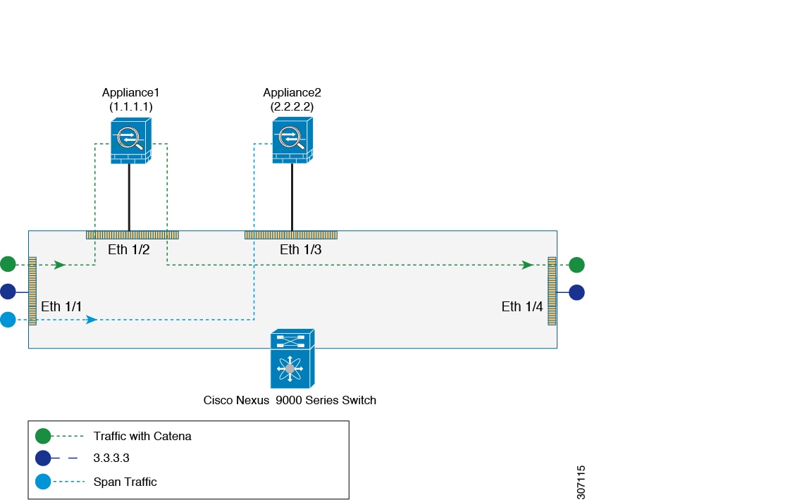
In this configuration, the ingress Layer 3 traffic (3.3.3.3) is redirected using catena to 1.1.1.1 and also the same ingress Layer 3 traffic is remote spanned to device 2.2.2.2.

Figure 10. SPAN Support: Routed Mode
switch# show running-config catena
feature catena

catena device-group dg1
  node ip 1.1.1.1
 erspan-ip 3.3.3.3
catena device-group dg2
  node ip 2.2.2.2

catena port-group pg1
  interface Eth1/1

catena instance1
  chain 10
    10 access-list acl1 ingress-port-group pg1 egress-device-group dg2 span
    20 access-list acl1 ingress-port-group pg1 egress-device-group dg1 mode forward
  no shutdown

Transparent Mode (Port-based):

In this configuration, the ingress Layer 2 traffic is redirected using catena to Appliance1 and also the same Layer 2 ingress traffic is spanned to interface Eth1/3, which may be connected to a monitoring device.

Figure 11. SPAN Support: Transparent Mode (Port-based)
switch# show running-config catena
feature catena

catena port-acl test
 10 permit ip 10.1.1.1/24 any
 20 permit ip 20.20.10.1 0.0.0.255 30.30.30.30/24
 30 permit ip 70.7.7.7 255.255.255.0 80.80.80.8 255.255.255.0
 40 deny ip 30.30.30.30 0.0.0.255 any

catena port-group pg1
  interface Eth1/1
catena port-group pg2
  interface Eth1/2
catena port-group pg3
  interface Eth1/3
catena instance1
  chain 10
    10 access-list test ingress-port-group pg1 egress-port-group pg3 span
    20 access-list test ingress-port-group pg1 egress-port-group pg2 mode forward
  no shutdown

Transparent Mode (VLAN-based):

In this configuration, the ingress Layer 2 traffic on vlan10 is redirected using catena to Appliance1 and also the same Layer 2 ingress traffic is spanned to interface Eth1/3, which may be connected to a monitoring device.

Figure 12. SPAN Support: Transparent Mode (Vlan-based )
switch# show running-config catena
feature catena

catena vlan-group vg1
  vlan 10
catena port-group pg1
  interface Eth1/2
catena port-group pg2
  interface Eth1/3

catena instance1
  chain 10
    10 access-list acl1 vlan-group vg1 egress-port-group pg2 span
    20 access-list acl1 vlan-group vg1 egress-port-group pg1 mode forward
  no shutdown