Enabling Chaining Using Deployment Modes

Enabling Chaining using Deployment Modes

You can create multiple chains, each comprising multiple functions and services; configure each chain to run on multiple devices; and apply network policies to these elements. You can create chains using the following deployment modes:

  • Transparent mode

  • Routed mode

  • Mixed mode, including both Transparent and Routed mode in the same chain

Transparent Mode

The following figure shows the traffic flow between appliances in the transparent mode when catena is enabled, enabled with bad traffic, and disabled.

Figure 1. Transparent Mode

TCAM Based Load Balancing

The following figure shows how Catena uses a cross function of IP-ACL entries along with TCAM FIB to bucket the traffic streams to multiple egress interfaces.

Figure 2. Transparent Mode

Hash Based Load Balancing

Catena uses source IP or destination IP to determine the egress interface. Egress interface ports are bundled using the link aggregation control protocol (LACP), and hash algorithms are used for symmetric load balancing.

Routed Mode

The following figure shows the traffic flow between appliances in the routed mode when catena is enabled, enabled with bad traffic, and disabled.

Figure 3. Routed Mode

VRF Support

You can configure catena service in the default VRF or in non-default VRFs.

For the catena service to successfully redirect traffic, all the ingress interfaces and device-group nodes must belong to the same VRF. You must ensure that all ingress interfaces and node members within the associated device group are reachable in the configured VRF.

Reverse Configuration

Reverse configuration is a solution that defines the egress interface in the reverse direction for each segment of the chain based on port number or IP address. In order to generate the reverse configuration, it is necessary to define each segment of the egress interface when you configure your Catena instance.

Guidelines and Limitations for layer 3 Reverse Configuration:

  • Mapping of the node IP with the port interface is auto generated by Catena and needs no explicit configuration.

  • Configuring the intermediate device groups along with target IP address is sufficient.

For details on how to configure Reverse Configuration see, Configuring a Catena Instance.

To view sample configurations see, Configuration Examples of Catena Instances.

Fail-Action Mode Support for Catena

When one of the appliances in the chain goes down, Catena supports three different failure modes of operation: forward, bypass, and drop mode.

  • In forward mode, traffic uses the default routing table and ignores the rest of the sequences in the chain.

  • In bypass mode, traffic bypasses the failed node and is re-directed to the next available node in the chain.

  • In drop mode, traffic is dropped at the Nexus device when there is failure of a node.

The following figure is an example of Layer 3 Fail-Action forward mode. To view sample configurations see, Configuration Examples of Catena Instances.

Figure 4. Layer 3 Fail-Action Mode: Forward Mode

SPAN Support for Catena

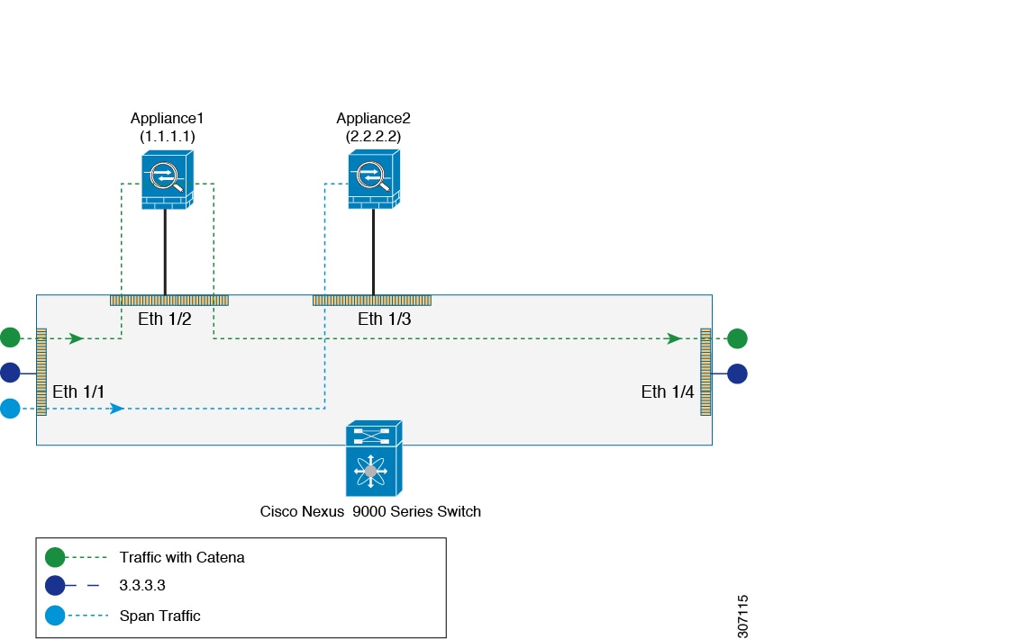
For each Catena sequence, the packets can be forwarded or redirected to an appliance. The same traffic (that is, a copy of the traffic) can be sent to another appliance (such as sniffer devices or span devices) for troubleshooting and monitoring applications purpose. You can redirect the traffic to an appliance, and, if necessary, you can SPAN the traffic to the appliance.

The following figure is an example of SPAN support in routed mode. To view sample configurations see, Configuration Examples of Catena Instances.

Figure 5. SPAN Support: Routed Mode