Configuring EVPN VXLAN Layer 2 Overlay with Q-in-VNI

IEEE 802.1Q over Layer 2 VNI (Q-in-VNI) over EVPN VXLAN network addresses the requirement of limited network Layer 2 extension and isolation by carrying the IEEE 802.1Q tag transparently within the VXLAN header. This enables a Network-to-Network Interface (NNI) Layer 2 trunk interface with one or more 802.1Q segmented network to transport over a single Layer 2 VNI across the BGP EVPN VXLAN fabric network. Q-in-VNI provides a greater number of virtual networks to be created, with the necessary flexibility and scalability for campus network environments and other situations where a large number of Layer 2 overlays are required in a BGP EVPN VXLAN fabric.

Restrictions for EVPN VXLAN Layer 2 Overlay with Q-in-VNI

  • Selective Q-in-VNI and Q-in-VNI with VLAN mapping are not supported in this release.

  • The dot1q-tunnel switchport mode access VLAN ID (S-VLAN) must be unique and should not be assigned to trunk VLAN ID (C-VLAN).

  • Layer 2 Protocol Tunneling (L2PT) is not supported on an 802.1Q tunnel port that is mapped for BGP EVPN Layer 2 fabric network extension.

  • BGP EVPN Layer 3 IP Routing function is not supported on those VLANs that are mapped to 802.1Q tunnel port.

  • Overlapping MAC entry between multiple C-VLANs under a single EVPN-mapped S-VLAN is not supported.

Information About Q-in-VNI

Enterprise campus, data centers, and service provider networks are often required to become a carrier network and provide transparent Layer 2 bridging between statically assigned physical Layer 2 trunk interfaces. Such networks have specific requirements for VLAN IDs and the number of VLANs to be supported. The VLAN ranges required by different customers in the same service provider network might overlap, and traffic of customers through the infrastructure might be mixed. Assigning a unique range of VLAN IDs to each customer would restrict the customer configurations and could easily exceed the VLAN limit (4094) specified by the IEEE 802.1Q standard.

Using the Q-in-VNI feature, service providers can use a single VLAN (S-VLAN) to support customers who have multiple VLANs (C-VLAN). Each customer's VLAN IDs are preserved, and traffic from different customers is segregated within the service provider network, though they appear to be in the same VLAN. Deploying IEEE 802.1Q tunneling expands the VLAN space by using a VLAN-in-VLAN hierarchy and retagging the tagged packets. A port configured to support IEEE 802.1Q tunneling is called a tunnel port. When tunneling is configured, a tunnel port is assigned to a VLAN ID that is dedicated to tunneling. Each customer is provided with a unique service provider VLAN ID that supports all the VLANs of the customer.

Q-in-VNI in a BGP EVPN VXLAN Fabric

Using the Q-in-VNI feature, a service provider can provide Layer 2 overlay services by mapping the S-VLAN to the Layer 2 VNI. This allows the service providers to address their business customers' Layer 2 connectivity requirements with BGP EVPN VXLAN between the campus sites or a data center.

Enterprise customers can also deploy the Q-in-VNI feature within a single site by mapping the traffic from multiple Layer 2 segments into a specific S-VLAN with EVPN EVI enabled, and with the following criteria:

  • The site is bounded by the number of L2VNI overlay segments that are supported by a specific Cisco Catalyst 9000 series switch.

  • VLAN segments are symmetric across the fabric edges.


Note


When the Q-in-VNI Layer 2 overlay service with the S-VLAN mapped to an EVPN Instance (also known as MAC VRF) is deployed, the end host MAC routes (RT2) belonging to all the C-VLANs are maintained in a single bridge table corresponding to the S-VLAN.


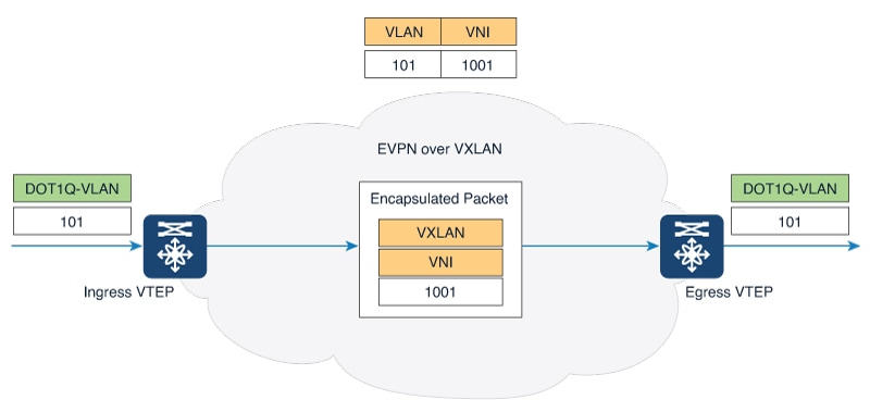
In a BGP EVPN VXLAN fabric with Layer 2 interfaces that have trunk port configuration (Figure), the ingress VTEP strips the IEEE 802.1Q tag and encapsulates a Layer 2 packet with a VXLAN header and forwards the packet to the destination. At the egress VTEP, the packet is decapsulated and L2VNI is mapped to the corresponding VLAN. If the egress port is a trunk port, the corresponding VLAN ID is populated in the IEEE 802.1Q header, and the packet is sent out of the fabric.

Figure 1. EVPN VXLAN Fabric with Trunk Mode on the Access Port

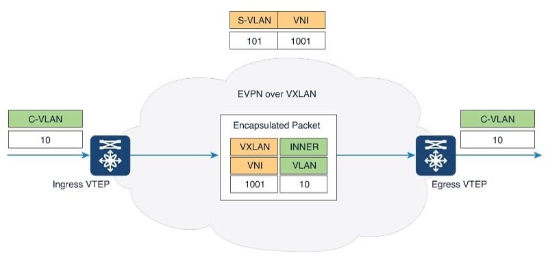
When Q-in-VNI is configured (example topology shown below), customer traffic from C-VLAN with a VLAN ID of 10 is forwarded to the EVPN VXLAN overlay network. The ingress VTEP port in the overlay network is configured as a Q-in-VNI port with a provider VLAN 101 and a unique Layer 2 VNI of 1001. When a packet enters the Q-in-VNI tunnel port on the edge device, it is encapsulated with an outer VXLAN header containing the VNI 1001 (the original inner header with a VLAN 10 is retained). At the Egress VTEP, the packet is forwarded to the correct Q-in-VNI port, based on the matching provider VLAN 101 that is derived from Layer 2 VNI. At the outbound tunnel port, the packet is transmitted with the original C-VLAN tag.

Figure 2. Q-in-VNI over Layer 2 BGP EVPN VXLAN on 802.1Q Tunnel Mode port

How to Configure Q-in-VNI in a BGP EVPN VXLAN Fabric

Configure the access interface for Q-in-VNI tunneling.

Before you begin

Ensure that the Layer 2 overlay is configured as described in the Configuring Layer 2 Overlay Network chapter for the S-VLAN.

Procedure

  Command or Action Purpose

Step 1

enable

Example:

Device> enable

Enables privileged EXEC mode.

Enter your password, if prompted.

Step 2

configure terminal

Example:

Device# configure terminal

Enters global configuration mode.

Step 3

interface interface-name

Example:

Device(config)# interface GigabitEthernet1/0/24

Enters interface configuration mode for the interface to be configured as a tunnel port.

This should be the edge port on the VTEP that connects to the interface of the Layer 2 device with a trunk port configuration.

Step 4

switchport access vlan vlan-id

Example:

Device(config-if)# switchport access vlan 101

Specifies the S-VLAN that is mapped to the L2VNI.

Step 5

switchport mode dot1q-tunnel

Example:

Device(config-if)# switchport mode dot1q-tunnel

Sets the interface as an IEEE 802.1Q tunnel port.

Step 6

end

Example:

Device(config-if)# end

Returns to privileged EXEC mode.

Example: Configuring Q-in-VNI in a BGP EVPN VXLAN Fabric


Note


Before you enable Q-in-VNI on the interface, ensure that the EVPN VXLAN Layer 2 overlay network is configured. For an example configuration of an EVPN VXLAN Layer 2 overlay, refer to the "Configuring EVPN VXLAN Layer 2 Overlay Network" chapter.


The following example shows how to configure an interface as a tunnel port to the enable Q-in-VNI feature in an EVPN VXLAN Layer 2 overlay network. In this configuration, the VLAN ID for the customer connected to Gigabit Ethernet interface 24 on stack member 1 is VLAN 101.

l2vpn evpn instance 101 vlan-based
 encapsulation vxlan
 replication-type static
!
vlan configuration 101        <--- S-VLAN mapped to VNI
 member evpn-instance 101 vni 1001 
!
interface nve1
 no ip address
 source-interface Loopback1
 host-reachability protocol bgp
 member vni 1001 mcast-group 225.0.0.101
!
interface GigabitEthernet1/0/24
 switchport access vlan 101   <--- S-VLAN
 switchport mode dot1q-tunnel
 no cdp enable
!