Configuring IP Unicast Routing

Restrictions for IP Unicast Routing

  • The switch does not support tunnel interfaces for unicast routed traffic.

  • Subnetwork Access Protocol (SNAP) address resolution is not supported on this device.

Information About Configuring IP Unicast Routing

This module describes how to configure IP Version 4 (IPv4) unicast routing on the switch.


Note


In addition to IPv4 traffic, you can also enable IP Version 6 (IPv6) unicast routing and configure interfaces to forward IPv6 traffic .


Information About IP Routing

In some network environments, VLANs are associated with individual networks or subnetworks. In an IP network, each subnetwork is mapped to an individual VLAN. Configuring VLANs helps control the size of the broadcast domain and keeps local traffic local. However, network devices in different VLANs cannot communicate with one another without a Layer 3 device (router) to route traffic between the VLAN, referred to as inter-VLAN routing. You configure one or more routers to route traffic to the appropriate destination VLAN.

Figure 1. Routing Topology Example. This figure shows a basic routing topology. Switch A is in VLAN 10, and Switch B is in VLAN 20. The router has an interface in each VLAN.

When Host A in VLAN 10 needs to communicate with Host B in VLAN 10, it sends a packet addressed to that host. Switch A forwards the packet directly to Host B, without sending it to the router.

When Host A sends a packet to Host C in VLAN 20, Switch A forwards the packet to the router, which receives the traffic on the VLAN 10 interface. The router checks the routing table, finds the correct outgoing interface, and forwards the packet on the VLAN 20 interface to Switch B. Switch B receives the packet and forwards it to Host C.

Types of Routing

Routers and Layer 3 switches can route packets in these ways:

  • By using default routing

  • By using preprogrammed static routes for the traffic

Classless Routing

By default, classless routing behavior is enabled on the device when it is configured to route. With classless routing, if a router receives packets for a subnet of a network with no default route, the router forwards the packet to the best supernet route. A supernet consists of contiguous blocks of Class C address spaces used to simulate a single, larger address space and is designed to relieve the pressure on the rapidly depleting Class B address space.

In the figure, classless routing is enabled. When the host sends a packet to 120.20.4.1, instead of discarding the packet, the router forwards it to the best supernet route. If you disable classless routing and a router receives packets destined for a subnet of a network with no network default route, the router discards the packet.

Figure 2. IP Classless Routing

In the figure , the router in network 128.20.0.0 is connected to subnets 128.20.1.0, 128.20.2.0, and 128.20.3.0. If the host sends a packet to 120.20.4.1, because there is no network default route, the router discards the packet.

Figure 3. No IP Classless Routing

To prevent the device from forwarding packets destined for unrecognized subnets to the best supernet route possible, you can disable classless routing behavior.

Address Resolution

You can control interface-specific handling of IP by using address resolution. A device using IP can have both a local address or MAC address, which uniquely defines the device on its local segment or LAN, and a network address, which identifies the network to which the device belongs.

The local address or MAC address is known as a data link address because it is contained in the data link layer (Layer 2) section of the packet header and is read by data link (Layer 2) devices. To communicate with a device on Ethernet, the software must learn the MAC address of the device. The process of learning the MAC address from an IP address is called address resolution . The process of learning the IP address from the MAC address is called reverse address resolution .

The device can use these forms of address resolution:

  • Address Resolution Protocol (ARP) is used to associate IP address with MAC addresses. Taking an IP address as input, ARP learns the associated MAC address and then stores the IP address/MAC address association in an ARP cache for rapid retrieval. Then the IP datagram is encapsulated in a link-layer frame and sent over the network.

  • Proxy ARP helps hosts with no routing tables learn the MAC addresses of hosts on other networks or subnets. If the device (router) receives an ARP request for a host that is not on the same interface as the ARP request sender, and if the router has all of its routes to the host through other interfaces, it generates a proxy ARP packet giving its own local data link address. The host that sent the ARP request then sends its packets to the router, which forwards them to the intended host.

The device also uses the Reverse Address Resolution Protocol (RARP), which functions the same as ARP does, except that the RARP packets request an IP address instead of a local MAC address. Using RARP requires a RARP server on the same network segment as the router interface. Use the ip rarp-server address interface configuration command to identify the server.

Proxy ARP

Proxy ARP, the most common method for learning about other routes, enables an Ethernet host with no routing information to communicate with hosts on other networks or subnets. The host assumes that all hosts are on the same local Ethernet and that they can use ARP to learn their MAC addresses. If a device receives an ARP request for a host that is not on the same network as the sender, the device evaluates whether it has the best route to that host. If it does, it sends an ARP reply packet with its own Ethernet MAC address, and the host that sent the request sends the packet to the device, which forwards it to the intended host. Proxy ARP treats all networks as if they are local, and performs ARP requests for every IP address.

ICMP Router Discovery Protocol

Router discovery allows the device to dynamically learn about routes to other networks using ICMP router discovery protocol (IRDP). IRDP allows hosts to locate routers. When operating as a client, the device generates router discovery packets. When operating as a host, the device receives router discovery packets. The device can also listen to Routing Information Protocol (RIP) routing updates and use this information to infer locations of routers. The device does not actually store the routing tables sent by routing devices; it merely keeps track of which systems are sending the data. The advantage of using IRDP is that it allows each router to specify both a priority and the time after which a device is assumed to be down if no further packets are received.

Each device discovered becomes a candidate for the default router, and a new highest-priority router is selected when a higher priority router is discovered, when the current default router is declared down, or when a TCP connection is about to time out because of excessive retransmissions.

IRDP packets are not sent while enabling or disabling IP routing. When interface is shutting down, the last IRDP message do not have a lifetime; it is 0 for all routers.

UDP Broadcast Packets and Protocols

User Datagram Protocol (UDP) is an IP host-to-host layer protocol, as is TCP. UDP provides a low-overhead, connectionless session between two end systems and does not provide for acknowledgment of received datagrams. Network hosts occasionally use UDP broadcasts to find address, configuration, and name information. If such a host is on a network segment that does not include a server, UDP broadcasts are normally not forwarded. You can remedy this situation by configuring an interface on a router to forward certain classes of broadcasts to a helper address. You can use more than one helper address per interface.

You can specify a UDP destination port to control which UDP services are forwarded. You can specify multiple UDP protocols. You can also specify the Network Disk (ND) protocol, which is used by older diskless Sun workstations and the network security protocol SDNS.

By default, both UDP and ND forwarding are enabled if a helper address has been defined for an interface.

Broadcast Packet Handling

After configuring an IP interface address, you can enable routing and configure one or more routing protocols, or you can configure the way the device responds to network broadcasts. A broadcast is a data packet destined for all hosts on a physical network. The device supports two kinds of broadcasting:

  • A directed broadcast packet is sent to a specific network or series of networks. A directed broadcast address includes the network or subnet fields.

  • A flooded broadcast packet is sent to every network.


    Note


    You can also limit broadcast, unicast, and multicast traffic on Layer 2 interfaces by using the storm-control interface configuration command to set traffic suppression levels.


Routers provide some protection from broadcast storms by limiting their extent to the local cable. Bridges (including intelligent bridges), because they are Layer 2 devices, forward broadcasts to all network segments, thus propagating broadcast storms. The best solution to the broadcast storm problem is to use a single broadcast address scheme on a network. In most modern IP implementations, you can set the address to be used as the broadcast address. Many implementations, including the one in the device, support several addressing schemes for forwarding broadcast messages.

IP Broadcast Flooding

You can allow IP broadcasts to be flooded throughout your internetwork in a controlled fashion by using the database created by the bridging STP. Using this feature also prevents loops. To support this capability, bridging must be configured on each interface that is to participate in the flooding. If bridging is not configured on an interface, it still can receive broadcasts. However, the interface never forwards broadcasts it receives, and the router never uses that interface to send broadcasts received on a different interface.

Packets that are forwarded to a single network address using the IP helper-address mechanism can be flooded. Only one copy of the packet is sent on each network segment.

To be considered for flooding, packets must meet these criteria. (Note that these are the same conditions used to consider packet forwarding using IP helper addresses.)

  • The packet must be a MAC-level broadcast.

  • The packet must be an IP-level broadcast.

  • The packet must be a TFTP, DNS, Time, NetBIOS, ND, or BOOTP packet, or a UDP specified by the ip forward-protocol udp global configuration command.

  • The time-to-live (TTL) value of the packet must be at least two.

A flooded UDP datagram is given the destination address specified with the ip broadcast-address interface configuration command on the output interface. The destination address can be set to any address. Thus, the destination address might change as the datagram propagates through the network. The source address is never changed. The TTL value is decremented.

When a flooded UDP datagram is sent out an interface (and the destination address possibly changed), the datagram is handed to the normal IP output routines and is, therefore, subject to access lists, if they are present on the output interface.

In the switch, the majority of packets are forwarded in hardware; most packets do not go through the switch CPU. For those packets that do go to the CPU, you can speed up spanning tree-based UDP flooding by a factor of about four to five times by using turbo-flooding. This feature is supported over Ethernet interfaces configured for ARP encapsulation.

Configuration Guidelines for IP Routing

By default, IP routing is disabled on the device, and you must enable it before routing can take place.

In the following procedures, the specified interface must be one of these Layer 3 interfaces:

  • A routed port: a physical port configured as a Layer 3 port by using the no switchport interface configuration command.

  • A switch virtual interface (SVI): a VLAN interface created by using the interface vlan vlan_id global configuration command and by default a Layer 3 interface.

  • An EtherChannel port channel in Layer 3 mode: a port-channel logical interface created by using the interface port-channel port-channel-number global configuration command and binding the Ethernet interface into the channel group.

All Layer 3 interfaces on which routing will occur must have IP addresses assigned to them.


Note


A Layer 3 switch can have an IP address assigned to each routed port and SVI.


Configuring routing consists of several main procedures:

  • To support VLAN interfaces, create and configure VLANs on the switch or switch stack, and assign VLAN membership to Layer 2 interfaces. For more information, see the "Configuring VLANs” chapter.

  • Configure Layer 3 interfaces.

  • Enable IP routing on the switch.

  • Assign IP addresses to the Layer 3 interfaces.

  • Enable selected routing protocols on the switch.

  • Configure routing protocol parameters (optional).

How to Configure IP Addressing

A required task for configuring IP routing is to assign IP addresses to Layer 3 network interfaces to enable the interfaces and allow communication with the hosts on those interfaces that use IP. The following sections describe how to configure various IP addressing features. Assigning IP addresses to the interface is required; the other procedures are optional.

Default IP Addressing Configuration

Table 1. Default Addressing Configuration

Feature

Default Setting

IP address

None defined.

ARP

No permanent entries in the Address Resolution Protocol (ARP) cache.

Encapsulation: Standard Ethernet-style ARP.

Timeout: 14400 seconds (4 hours).

IP broadcast address

255.255.255.255 (all ones).

IP classless routing

Enabled.

IP default gateway

Disabled.

IP directed broadcast

Disabled (all IP directed broadcasts are dropped).

IP domain

Domain list: No domain names defined.

Domain lookup: Enabled.

Domain name: Enabled.

IP forward-protocol

If a helper address is defined or User Datagram Protocol (UDP) flooding is configured, UDP forwarding is enabled on default ports.

Any-local-broadcast: Disabled.

Spanning Tree Protocol (STP): Disabled.

Turbo-flood: Disabled.

IP helper address

Disabled.

IP host

Disabled.

IRDP

Disabled.

Defaults when enabled:

  • Broadcast IRDP advertisements.

  • Maximum interval between advertisements: 600 seconds.

  • Minimum interval between advertisements: 0.75 times max interval

  • Preference: 0.

IP proxy ARP

Enabled.

IP routing

Disabled.

IP subnet-zero

Disabled.

Assigning IP Addresses to Network Interfaces

An IP address identifies a location to which IP packets can be sent. Some IP addresses are reserved for special uses and cannot be used for host, subnet, or network addresses. RFC 1166, “Internet Numbers,” contains the official description of IP addresses.

An interface can have one primary IP address. A mask identifies the bits that denote the network number in an IP address. When you use the mask to subnet a network, the mask is referred to as a subnet mask. To receive an assigned network number, contact your Internet service provider.

Procedure

  Command or Action Purpose

Step 1

enable

Example:


Device>enable

Enables privileged EXEC mode.

  • Enter your password if prompted.

Step 2

configure terminal

Example:


Device#configure terminal

Enters global configuration mode.

Step 3

interface interface-id

Example:


Device(config)#interface gigabitethernet 1/0/1

Enters interface configuration mode, and specifies the Layer 3 interface to configure.

Step 4

no switchport

Example:


Device(config-if)#no switchport

Removes the interface from Layer 2 configuration mode (if it is a physical interface).

Step 5

ip address ip-address subnet-mask

Example:


Device(config-if)#ip address 10.1.5.1 255.255.255.0

Configures the IP address and IP subnet mask.

Step 6

no shutdown

Example:


Device(config-if)#no shutdown

Enables the physical interface.

Step 7

end

Example:


Device(config)#end

Returns to privileged EXEC mode.

Step 8

show ip route

Example:


Device#show ip route

Verifies your entries.

Step 9

show ip interface [interface-id]

Example:


Device#show ip interface gigabitethernet 1/0/1

Verifies your entries.

Step 10

show running-config

Example:


Device#show running-config 

Verifies your entries.

Step 11

copy running-config startup-config

Example:


Device#copy running-config startup-config 

(Optional) Saves your entries in the configuration file.

Using Subnet Zero

Subnetting with a subnet address of zero is strongly discouraged because of the problems that can arise if a network and a subnet have the same addresses. For example, if network 131.108.0.0 is subnetted as 255.255.255.0, subnet zero would be written as 131.108.0.0, which is the same as the network address.

You can use the all ones subnet (131.108.255.0) and even though it is discouraged, you can enable the use of subnet zero if you need the entire subnet space for your IP address.

Use the no ip subnet-zero global configuration command to restore the default and disable the use of subnet zero.

Procedure
  Command or Action Purpose

Step 1

enable

Example:

Device>enable

Enables privileged EXEC mode.

Enter your password if prompted.

Step 2

configure terminal

Example:

Device#configure terminal

Enters global configuration mode.

Step 3

ip subnet-zero

Example:

Device(config)#ip subnet-zero

Enables the use of subnet zero for interface addresses and routing updates.

Step 4

end

Example:

Device(config)#end

Returns to privileged EXEC mode.

Step 5

show running-config

Example:

Device#show running-config 

Verifies your entries.

Step 6

copy running-config startup-config

Example:

Device#copy running-config startup-config 

(Optional) Saves your entries in the configuration file.

Disabling Classless Routing

To prevent the device from forwarding packets destined for unrecognized subnets to the best supernet route possible, you can disable classless routing behavior.

Procedure
  Command or Action Purpose

Step 1

enable

Example:

Device>enable

Enables privileged EXEC mode.

Enter your password if prompted.

Step 2

configure terminal

Example:

Device#configure terminal

Enters global configuration mode.

Step 3

no ip classless

Example:

Device(config)#no ip classless

Disables classless routing behavior.

Step 4

end

Example:

Device(config)#end

Returns to privileged EXEC mode.

Step 5

show running-config

Example:

Device#show running-config 

Verifies your entries.

Step 6

copy running-config startup-config

Example:

Device#copy running-config startup-config 

(Optional) Saves your entries in the configuration file.

Configuring Address Resolution Methods

You can perform the following tasks to configure address resolution.

Defining a Static ARP Cache

ARP and other address resolution protocols provide dynamic mapping between IP addresses and MAC addresses. Because most hosts support dynamic address resolution, you usually do not need to specify static ARP cache entries. If you must define a static ARP cache entry, you can do so globally, which installs a permanent entry in the ARP cache that the device uses to translate IP addresses into MAC addresses. Optionally, you can also specify that the device responds to ARP requests as if it were the owner of the specified IP address. If you do not want the ARP entry to be permanent, you can specify a timeout period for the ARP entry.

To define a static arp cache, perform this procedure:

Procedure
  Command or Action Purpose

Step 1

enable

Example:

Device>enable

Enables privileged EXEC mode.

Enter your password if prompted.

Step 2

configure terminal

Example:

Device#configure terminal

Enters global configuration mode.

Step 3

arp ip-address hardware-address type

Example:

Device(config)#ip 10.1.5.1 c2f3.220a.12f4 arpa

Associates an IP address with a MAC (hardware) address in the ARP cache, and specifies encapsulation type as one of these:

  • arpa —ARP encapsulation for Ethernet interfaces

  • sap —HP’s ARP type

Step 4

arp ip-address hardware-address type [alias]

Example:

Device(config)#ip 10.1.5.3 d7f3.220d.12f5 arpa alias

(Optional) Specifies that the switch responds to ARP requests as if it were the owner of the specified IP address.

Step 5

interface interface-id

Example:

Device(config)#interface gigabitethernet 1/0/1

Enters interface configuration mode, and specifies the interface to configure.

Step 6

arp timeout seconds

Example:

Device(config-if)#arp timeout 20000

(Optional) Sets the length of time an ARP cache entry stays in the cache. The recommended value of ARP timeout is 4 hours which is also the default setting. However, if your network experiences regular updates to ARP cache entries, consider changing the timeout. Note that decreasing the ARP timeout can result in increased network traffic. It is not recommended to set the ARP timeout to 60 seconds or less.

Step 7

end

Example:

Device(config)#end

Returns to privileged EXEC mode.

Step 8

show interfaces [interface-id]

Example:

Device#show interfaces gigabitethernet 1/0/1

Verifies the type of ARP and the timeout value that is used on all interfaces or a specific interface.

Step 9

show arp

Example:

Device#show arp

Views the contents of the ARP cache.

Step 10

show ip arp

Example:

Device#show ip arp

Views the contents of the ARP cache.

Step 11

copy running-config startup-config

Example:

Device#copy running-config startup-config 

(Optional) Saves your entries in the configuration file.

Setting ARP Encapsulation

By default, Ethernet ARP encapsulation (represented by the arpa keyword) is enabled on an IP interface.

Procedure
  Command or Action Purpose

Step 1

enable

Example:

Device>enable

Enables privileged EXEC mode.

Enter your password if prompted.

Step 2

configure terminal

Example:

Device#configure terminal

Enters global configuration mode.

Step 3

interface interface-id

Example:

Device(config)#interface gigabitethernet 1/0/2

Enters interface configuration mode, and specifies the Layer 3 interface to configure.

Step 4

arp arpa

Example:

Device(config-if)#arp arpa

Specifies the ARP encapsulation method.

Use the no arp arpa command to disable ARP encapsulation method.

Step 5

end

Example:

Device(config)#end

Returns to privileged EXEC mode.

Step 6

show interfaces [interface-id]

Example:

Device#show interfaces

Verifies ARP encapsulation configuration on all interfaces or the specified interface.

Step 7

copy running-config startup-config

Example:

Device#copy running-config startup-config 

(Optional) Saves your entries in the configuration file.

Enabling Proxy ARP

By default, the device uses proxy ARP to help hosts learn MAC addresses of hosts on other networks or subnets.

Procedure
  Command or Action Purpose

Step 1

enable

Example:

Device>enable 

Enables privileged EXEC mode.

Enter your password if prompted.

Step 2

configure terminal

Example:

Device#configure terminal

Enters global configuration mode.

Step 3

interface interface-id

Example:

Device(config)#interface gigabitethernet 1/0/2

Enters interface configuration mode, and specifies the Layer 3 interface to configure.

Step 4

ip proxy-arp

Example:

Device(config-if)#ip proxy-arp

Enables proxy ARP on the interface.

Step 5

end

Example:

Device(config)#end

Returns to privileged EXEC mode.

Step 6

show ip interface [interface-id]

Example:

Device#show ip interface gigabitethernet 1/0/2

Verifies the configuration on the interface or all interfaces.

Step 7

copy running-config startup-config

Example:

Device#copy running-config startup-config 

(Optional) Saves your entries in the configuration file.

Routing Assistance When IP Routing is Disabled

These mechanisms allow the device to learn about routes to other networks when it does not have IP routing enabled:

  • Proxy ARP

  • Default Gateway

  • ICMP Router Discovery Protocol (IRDP)

Proxy ARP

Proxy ARP is enabled by default. To enable it after it has been disabled, see the “Enabling Proxy ARP” section. Proxy ARP works as long as other routers support it.

Default Gateway

Another method for locating routes is to define a default router or default gateway. All non-local packets are sent to this router, which either routes them appropriately or sends an IP Control Message Protocol (ICMP) redirect message back, defining which local router the host should use. The device caches the redirect messages and forwards each packet as efficiently as possible. A limitation of this method is that there is no means of detecting when the default router has gone down or is unavailable.

Procedure
  Command or Action Purpose

Step 1

enable

Example:

Device>enable

Enables privileged EXEC mode.

Enter your password if prompted.

Step 2

configure terminal

Example:

Device#configure terminal

Enters global configuration mode.

Step 3

ip default-gateway ip-address

Example:

Device(config)#ip default gateway 10.1.5.1

Sets up a default gateway (router).

Step 4

end

Example:

Device(config)#end

Returns to privileged EXEC mode.

Step 5

show ip redirects

Example:

Device#show ip redirects

Displays the address of the default gateway router to verify the setting.

Step 6

copy running-config startup-config

Example:

Device#copy running-config startup-config 

(Optional) Saves your entries in the configuration file.

ICMP Router Discovery Protocol (IRDP)

The only required task for IRDP routing on an interface is to enable IRDP processing on that interface. When enabled, the default parameters apply.

You can optionally change any of these parameters. If you change the maxadvertinterval value, the holdtime and minadvertinterval values also change, so it is important to first change the maxadvertinterval value, before manually changing either the holdtime or minadvertinterval values.

Procedure
  Command or Action Purpose

Step 1

enable

Example:

Device>enable

Enables privileged EXEC mode.

  • Enter your password if prompted.

Step 2

configure terminal

Example:

Device#configure terminal

Enters global configuration mode.

Step 3

interface interface-id

Example:

Device(config)#interface gigabitethernet 1/0/1

Enters interface configuration mode, and specifies the Layer 3 interface to configure.

Step 4

ip irdp

Example:

Device(config-if)#ip irdp

Enables IRDP processing on the interface.

Step 5

ip irdp multicast

Example:

Device(config-if)#ip irdp multicast

(Optional) Sends IRDP advertisements to the multicast address (224.0.0.1) instead of IP broadcasts.

Note


This command allows for compatibility with Sun Microsystems Solaris, which requires IRDP packets to be sent out as multicasts. Many implementations cannot receive these multicasts; ensure end-host ability before using this command.

Step 6

ip irdp holdtime seconds

Example:

Device(config-if)#ip irdp holdtime 1000

(Optional) Sets the IRDP period for which advertisements are valid. The default is three times the maxadvertinterval value. It must be greater than maxadvertinterval and cannot be greater than 9000 seconds. If you change the maxadvertinterval value, this value also changes.

Step 7

ip irdp maxadvertinterval seconds

Example:

Device(config-if)#ip irdp maxadvertinterval 650

(Optional) Sets the IRDP maximum interval between advertisements. The default is 600 seconds.

Step 8

ip irdp minadvertinterval seconds

Example:

Device(config-if)#ip irdp minadvertinterval 500

(Optional) Sets the IRDP minimum interval between advertisements. The default is 0.75 times the maxadvertinterval . If you change the maxadvertinterval , this value changes to the new default (0.75 of maxadvertinterval ).

Step 9

ip irdp preference number

Example:

Device(config-if)#ip irdp preference 2

(Optional) Sets a device IRDP preference level. The allowed range is –231 to 231. The default is 0. A higher value increases the router preference level.

Step 10

ip irdp address address [number]

Example:

Device(config-if)#ip irdp address 10.1.10.10

(Optional) Specifies an IRDP address and preference to proxy-advertise.

Step 11

end

Example:

Device(config)#end

Returns to privileged EXEC mode.

Step 12

show ip irdp

Example:

Device#show ip irdp

Verifies settings by displaying IRDP values.

Step 13

copy running-config startup-config

Example:

Device#copy running-config startup-config 

(Optional) Saves your entries in the configuration file.

Configuring Broadcast Packet Handling

Perform the tasks in these sections to enable these schemes:

  • Enabling Directed Broadcast-to-Physical Broadcast Translation

  • Forwarding UDP Broadcast Packets and Protocols

  • Establishing an IP Broadcast Address

  • Flooding IP Broadcasts

Enabling Directed Broadcast-to-Physical Broadcast Translation

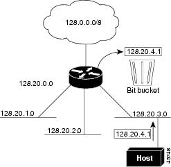
By default, IP directed broadcasts are dropped; they are not forwarded. Dropping IP-directed broadcasts makes routers less susceptible to denial-of-service attacks.

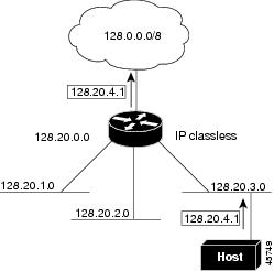
You can enable forwarding of IP-directed broadcasts on an interface where the broadcast becomes a physical (MAC-layer) broadcast. Only those protocols configured by using the ip forward-protocol global configuration command are forwarded.

You can specify an access list to control which broadcasts are forwarded. When an access list is specified, only those IP packets permitted by the access list are eligible to be translated from directed broadcasts to physical broadcasts. For more information on access lists, see the “Configuring ACLs" chapter in the Security Configuration Guide.


Note


The ip network-broadcast command must be configured at the ingress interface before configuring the ip directed-broadcast command at the egress interface. This ensures that the IP-directed broadcasts work correctly and prevents an outage from occurring after an upgrade.


Procedure
  Command or Action Purpose

Step 1

enable

Example:

Device>enable

Enables privileged EXEC mode.

Enter your password if prompted.

Step 2

configure terminal

Example:

Device#configure terminal

Enters global configuration mode.

Step 3

interface interface-id

Example:

Device(config)#interface gigabitethernet 1/0/2

Enters interface configuration mode, and specifies the interface to configure.

Step 4

ip network-broadcast

Example:
Device(config-if)#ip network-broadcast

Enables the ingress interface to receive and accept the network-prefix-directed broadcast packets.

Step 5

exit

Example:

Device(config-if)#exit

Returns to global configuration mode.

Step 6

interface interface-id

Example:

Device(config)#interface gigabitethernet 1/0/3

Enters interface configuration mode, and specifies the interface to configure.

Step 7

ip directed-broadcast [access-list-number]

Example:

Device(config-if)#ip directed-broadcast 103

Enables directed broadcast-to-physical broadcast translation on the interface. You can include an access list to control which broadcasts are forwarded. When an access list, only IP packets permitted by the access list can be translated.

Step 8

exit

Example:

Device(config-if)#exit

Returns to global configuration mode.

Step 9

ip forward-protocol {udp [port] | nd | sdns}

Example:

Device(config)#ip forward-protocol nd

Specifies which protocols and ports the router forwards when forwarding broadcast packets.

  • udp —Forward UPD datagrams.

    port: (Optional) Destination port that controls which UDP services are forwarded.

  • nd —Forward ND datagrams.

  • sdns —Forward SDNS datagrams

Step 10

end

Example:

Device(config)#end

Returns to privileged EXEC mode.

Step 11

show ip interface [interface-id]

Example:

Device#show ip interface

Verifies the configuration on the interface or all interfaces

Step 12

show running-config

Example:

Device#show running-config 

Verifies your entries.

Step 13

copy running-config startup-config

Example:

Device#copy running-config startup-config 

(Optional) Saves your entries in the configuration file.

Forwarding UDP Broadcast Packets and Protocols

If you do not specify any UDP ports when you configure the forwarding of UDP broadcasts, you are configuring the router to act as a BOOTP forwarding agent. BOOTP packets carry DHCP information.

Procedure
  Command or Action Purpose

Step 1

enable

Example:

Device>enable

Enables privileged EXEC mode.

Enter your password if prompted.

Step 2

configure terminal

Example:

Device#configure terminal

Enters global configuration mode.

Step 3

interface interface-id

Example:

Device(config)#interface gigabitethernet 1/0/1

Enters interface configuration mode, and specifies the Layer 3 interface to configure.

Step 4

ip helper-address address

Example:

Device(config-if)#ip helper address 10.1.10.1

Enables forwarding and specifies the destination address for forwarding UDP broadcast packets, including BOOTP.

Step 5

exit

Example:

Device(config-if)#exit

Returns to global configuration mode.

Step 6

ip forward-protocol {udp [port] | nd | sdns}

Example:

Device(config)#ip forward-protocol sdns

Specifies which protocols the router forwards when forwarding broadcast packets.

Step 7

end

Example:

Device(config)#end

Returns to privileged EXEC mode.

Step 8

show ip interface [interface-id]

Example:

Device#show ip interface gigabitethernet 1/0/1

Verifies the configuration on the interface or all interfaces.

Step 9

show running-config

Example:

Device#show running-config 

Verifies your entries.

Step 10

copy running-config startup-config

Example:

Device#copy running-config startup-config 

(Optional) Saves your entries in the configuration file.

Establishing an IP Broadcast Address

The most popular IP broadcast address (and the default) is an address consisting of all ones (255.255.255.255). However, the switch can be configured to generate any form of IP broadcast address.

Procedure
  Command or Action Purpose

Step 1

enable

Example:

Device>enable

Enables privileged EXEC mode.

Enter your password if prompted.

Step 2

configure terminal

Example:

Device#configure terminal

Enters global configuration mode.

Step 3

interface interface-id

Example:

Device(config)#interface gigabitethernet 1/0/1

Enters interface configuration mode, and specifies the interface to configure.

Step 4

ip broadcast-address ip-address

Example:

Device(config-if)#ip broadcast-address 128.1.255.255

Enters a broadcast address different from the default, for example 128.1.255.255.

Step 5

end

Example:

Device(config)#end

Returns to privileged EXEC mode.

Step 6

show ip interface [interface-id]

Example:

Device#show ip interface

Verifies the broadcast address on the interface or all interfaces.

Step 7

copy running-config startup-config

Example:

Device#copy running-config startup-config 

(Optional) Saves your entries in the configuration file.

Flooding IP Broadcasts

To configure IP broadcasts flooding, perform this procedure.

Procedure
  Command or Action Purpose

Step 1

enable

Example:

Device>enable

Enables privileged EXEC mode.

Enter your password if prompted.

Step 2

configure terminal

Example:

Device#configure terminal

Enters global configuration mode.

Step 3

ip forward-protocol spanning-tree

Example:

Device(config)#ip forward-protocol spanning-tree

Uses the bridging spanning-tree database to flood UDP datagrams.

Step 4

ip forward-protocol turbo-flood

Example:

Device(config)#ip forward-protocol turbo-flood

Uses the spanning-tree database to speed up flooding of UDP datagrams.

Step 5

end

Example:

Device(config)#end

Returns to privileged EXEC mode.

Step 6

show running-config

Example:

Device#show running-config 

Verifies your entries.

Step 7

copy running-config startup-config

Example:

Device#copy running-config startup-config 

(Optional) Saves your entries in the configuration file.

How to Configure IP Unicast Routing

The following sections provide configuration infornation about IP unicast routing.

Enabling IP Unicast Routing

By default, the device is in Layer 2 switching mode and IP routing is disabled. To use the Layer 3 capabilities of the device, you must enable IP routing.

Procedure

  Command or Action Purpose

Step 1

enable

Example:


Device>enable

Enables privileged EXEC mode.

Enter your password if prompted.

Step 2

configure terminal

Example:


Device#configure terminal

Enters global configuration mode.

Step 3

ip routing

Example:


Device(config)#ip routing

Enables IP routing.

Step 4

end

Example:


Device(config)#end

Returns to privileged EXEC mode.

Step 5

show running-config

Example:


Device#show running-config 

Verifies your entries.

Step 6

copy running-config startup-config

Example:


Device#copy running-config startup-config 

(Optional) Saves your entries in the configuration file.

What to Do Next

You can now set up parameters for the selected routing protocols as described in these sections:

  • RIP

  • OSPF,

  • EIGRP

  • BGP

  • Unicast Reverse Path Forwarding

  • Protocol-Independent Features (optional)

Configuration Example: Enabling IP Routing

This example shows how to enable IP routing:


Device#configure terminal
Enter configuration commands, one per line.  End with CNTL/Z.
Device(config)#ip routing
Device(config-router)#end

Monitoring and Maintaining IP Addressing

When the contents of a particular cache, table, or database have become or are suspected to be invalid, you can remove all its contents by using the clear privileged EXEC commands. The Table lists the commands for clearing contents.

Table 2. Commands to Clear Caches, Tables, and Databases

Command

Purpose

clear arp-cache

Clears the IP ARP cache and the fast-switching cache.

clear host {name | *}

Removes one or all entries from the hostname and the address cache.

clear ip route {network [mask] | *}

Removes one or more routes from the IP routing table.

You can display specific statistics, such as the contents of IP routing tables, caches, and databases; the reachability of nodes; and the routing path that packets are taking through the network. The Table lists the privileged EXEC commands for displaying IP statistics.

Table 3. Commands to Display Caches, Tables, and Databases

Command

Purpose

show arp

Displays the entries in the ARP table.

show hosts

Displays the default domain name, style of lookup service, name server hosts, and the cached list of hostnames and addresses.

show ip aliases

Displays IP addresses mapped to TCP ports (aliases).

show ip arp

Displays the IP ARP cache.

show ip interface [interface-id]

Displays the IP status of interfaces.

show ip irdp

Displays IRDP values.

show ip masks address

Displays the masks used for network addresses and the number of subnets using each mask.

show ip redirects

Displays the address of a default gateway.

show ip route [address [mask]] | [protocol]

Displays the current state of the routing table.

show ip route summary

Displays the current state of the routing table in summary form.

Monitoring and Maintaining the IP Network

You can remove all contents of a particular cache, table, or database. You can also display specific statistics.

Table 4. Command to Clear IP Routes or Display Route Status
Command Purpose

show ip route summary

Displays the current state of the routing table in summary form.

Feature Information for IP Unicast Routing

Table 5. Feature Information for IP Unicast Routing

Release

Feature

Feature Information

Cisco IOS XE Everest 16.6.1

IP Unicast Routing

IP Unicast Routing is a routing process that forwards traffic to an unicast address. Routers and Layer 3 switches route packets either through preprogrammed static routes or through default routes.

Cisco IOS XE Amsterdam 17.3.1

New command ip network-broadcast

ip network-broadcast command was introduced to receive and accept network-prefix-directed broadcast packets.