Restrictions for BGP EVPN VXLAN
BGP EVPN VXLAN does not support Generic Routing Encapsulation (GRE) in the underlay.
The documentation set for this product strives to use bias-free language. For the purposes of this documentation set, bias-free is defined as language that does not imply discrimination based on age, disability, gender, racial identity, ethnic identity, sexual orientation, socioeconomic status, and intersectionality. Exceptions may be present in the documentation due to language that is hardcoded in the user interfaces of the product software, language used based on RFP documentation, or language that is used by a referenced third-party product. Learn more about how Cisco is using Inclusive Language.
BGP EVPN VXLAN does not support Generic Routing Encapsulation (GRE) in the underlay.
BGP EVPN VXLAN is a campus network solution for Cisco Catalyst 9000 Series Switches running Cisco IOS XE software. This solution is a result of ratified IETF RFC specifications RFC 7432 and RFC 8365 supporting BGP EVPN control plane with RFC 7348 VXLAN data-plane. In addition multiple other BGP EVPN RFCs and Internet drafts submitted by the BGP Enabled ServicesS (bess1) workgroup are supported. It is designed to provide a unified overlay network solution and also address the challenges and drawbacks of existing technologies.
This chapter provides a background for the evolution of the solution and covers conceptual information and basic terminology that is required to understand BGP EVPN VXLAN. Later chapters of this configuration guide cover information about configuration, implementation, functionalities, and troubleshooting BGP EVPN VXLAN.
Traditionally, VLANs have been the standard method for providing network segmentation in campus networks. VLANs use loop prevention techniques such as Spanning Tree Protocol (STP), which impose restrictions on network design and resiliency. Further, there is a limitation with the number of VLANs that can be used to address layer 2 segments (4094 VLANs). Therefore, VLANs are a limiting factor for IT departments and cloud providers who build large and complex campus networks.
VXLAN is designed to overcome the inherent limitations of VLANs and STP. It is a proposed IETF standard [RFC 7348] to provide the same Ethernet Layer 2 network services as VLANs do, but with greater flexibility. Functionally, VXLAN is a MAC-in-UDP encapsulation protocol that runs as a virtual overlay on an existing Layer 3 network.
However, VXLAN by itself does not provide optimal switching and routing capabilities in a network because it uses a “flood and learn” mechanism that limits scalability. "Flood and learn" mechanism is where the host’s information is flooded across the network for it to be reachable. To provide optimal switching and routing capabilities, a VXLAN overlay requires:
An underlying transport network that performs data plane forwarding to allow unicast communication between end points connected to the fabric.
A control plane that is capable of distributing Layer 2 and Layer 3 host reachability information across the network.
To meet these additional requirements, Internet drafts submitted by the bess workgroup (draft-ietf-bess-evpn-overlay-12) proposed MP-BGP to carry Layer 2 MAC and Layer 3 IP information simultaneously. MP-BGP incorporates Network Layer Reachability Information (NLRI) to achieve this. With MAC and IP information available together for forwarding decisions, routing and switching within a network is optimized. This also minimizes the use of the conventional "flood and learn" mechanism used by VXLAN and allows for scalability in the fabric. EVPN is the extension that allows BGP to transport Layer 2 MAC and Layer 3 IP information. This deployment is called a BGP EVPN VXLAN fabric (also referred to as VXLAN fabric).
Deploying an overlay-underlay architecture using BGP EVPN VXLAN provides the following advantages:
Scalability — VXLAN provides Layer 2 connectivity that allows for infrastructure that can scale to 16 million tenant networks. It overcomes the 4094-segment limitation of VLANs. This is necessary to address today’s multi-tenant cloud requirements.
Flexibility — VXLAN allows workloads to be placed anywhere, along with the traffic separation required, in a multitenant environment. The traffic separation is done by network segmentation using VXLAN segment IDs or VXLAN network identifiers (VNIs). Workloads for a tenant can be distributed across different physical devices but they are identified by their respective Layer 2 VNI or Layer 3 VNI.
Mobility — Virtual machines can be moved from one location to another without updating spine switch tables. This is because entities within the same tenant VXLAN network retain the same VXLAN segment ID, regardless of their location.
This section provides information about the various fundamental concepts and terminologies that are involved in the working of BGP EVPN VXLAN.
An overlay network is a virtual network that is built over an existing Layer 2 or Layer 3 network by forming a static or dynamic tunnel that runs on top of the physical network infrastructure. The existing Layer 2 or Layer 3 network is what forms the underlay and is covered further below in this chapter.
When a data packet is sent through an overlay, the original packet or frame is packaged or encapsulated at a source edge device with an outer header and dispatched toward an appropriate destination edge device. The intermediate network devices forward the packet based on the outer header but are not aware of the data in the original packet. At the destination edge device, the packet is decapsulated by stripping off the overlay header and then forwarded based on the actual data within.
In the context of BGP EVPN VXLAN, VXLAN is used as the overlay technology to encapsulate the data packets and tunnel the traffic over a Layer 3 network. VXLAN creates a Layer 2 overlay network by using a MAC-in-UDP encapsulation. A VXLAN header is added to the original Layer 2 frame and it is then placed within a UDP-IP packet. A VXLAN overlay network is also called as a VXLAN segment. Only host devices and virtual machines within the same VXLAN segment can communicate with each other.
Each VXLAN segment is identified through a 24-bit segment ID, termed the VXLAN network identifier. This ensures that up to 16 million VXLAN segments can be present within the same administrative domain.
Every VXLAN segment has tunnel edge devices known as Virtual Tunnel End points (VTEPs). These devices sit at the edge of the VXLAN network and are responsible for creating instances of VXLAN tunnels, and for performing VXLAN encapsulation and decapsulation.
A VTEP has a switch interface on the local LAN segment to support local endpoint communication through bridging, and an IP interface to interact with the transport IP network.
The IP interface has a unique IP address that identifies the VTEP on the transport IP network. The VTEP uses this IP address to encapsulate Ethernet frames and transmits the encapsulated packets to the transport network through the IP interface. A VTEP device also discovers the remote VTEPs for its VXLAN segments and learns remote MAC address-to-VTEP mappings through its IP interface.
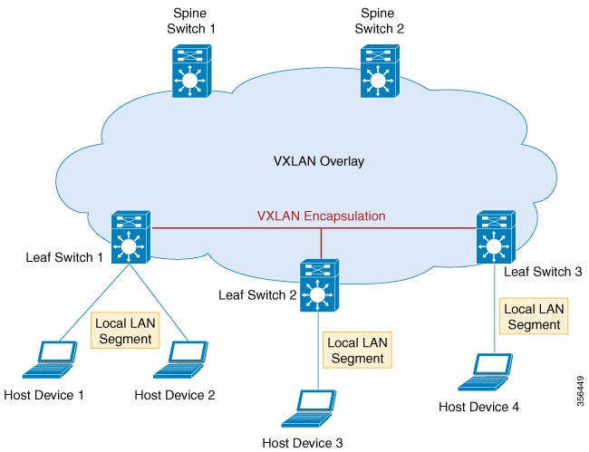
The following figure illustrates the working of an overlay VXLAN network connecting various VTEPs:
Overlay multicast is the method by which a overlay network forwards multicast traffic between various VTEPs present in the network. Tenant Routed Multicast (TRM) provides a mechanism to efficiently forward multicast traffic in a VXLAN overlay network. TRM is a BGP-EVPN based solution that enables multicast routing between sources and receivers connected on VTEPs in VXLAN fabric.
Without TRM, the multicast traffic is sent as part of the underlay network in the form of BUM traffic either using underlay multicast or ingress replication methods. This does not allow sources and receivers that are present across different subnets to communicate with each other. Using TRM, multicast communication is moved out of the BUM underlay traffic. This enables multicast communication in the overlay network irrespective of the subnet in which the source or the receiver resides.
An underlay network is the physical network over which the virtual overlay network is established. Once the overlay network is defined along with the data-plane encapsulation, a method of transport is required to move the data across the physical network underneath. This method of transport is typically an underlay transport network, or simply the underlay.
In BGP EVPN VXLAN, the underlay Layer 3 network transports the VXLAN-encapsulated packets between the source and destination VTEPs and provides reachability between them. The VXLAN overlay and the underlying IP network between the VTEPs are independent of each other.
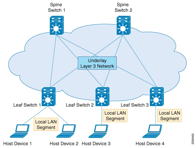
The following figure illustrates an underlay network:
The overlay requires a mechanism to know which end host device is behind which overlay edge device. VXLAN natively operates on a flood and learn mechanism where broadcast, unknown unicast and multicast (BUM) traffic in a given VXLAN network is sent over the IP core to every VTEP that has membership in that network. IP multicast is used to send traffic over the network. The receiving VTEPs decapsulate the packet and, based on the inner frame, perform Layer 2 MAC learning. The inner source MAC address is learned against the outer source IP address corresponding to the source VTEP. In this way, reverse traffic is unicasted toward the previously learnt end host.
The drawback of the flood and learn mechanism is that it does not allow scalability in a VXLAN network. In order to address this issue, a control plane is used to manage the MAC address learning and VTEP discovery. In BGP EVPN VXLAN deployments, Ethernet Virtual Private Network (EVPN) is used as the control plane. EVPN control plane provides the capability to exchange both MAC address and IP address information. EVPN uses Multi Protocol Border Gateway Protocol (MP-BGP) as the routing protocol to distribute reachability information pertaining to the VXLAN overlay network, including endpoint MAC addresses, endpoint IP addresses, and subnet reachability information. BGP EVPN distribution protocol facilitates the mapping information to be built by the tunnel edge devices in the location-identity mapping database.
A route target is an extended attribute in EVPN route updates that controls route distribution in a multi-tenant network. EVPN VTEPs have an import route target setting and an export route target setting for every VRF and Layer 2 Virtual Network Instance (VNI). When a VTEP advertises EVPN routes, it affixes its export route target in the route update. These routes are received by the other VTEPs in the network. The receiving VTEPs compare the route target value carried with the route against their own local import route target setting. If the two values match, the route is accepted and programmed in the routing table. Otherwise, the route is not imported.
The EVPN control plane advertises the following types of information:
Route type 1 – This is an Ethernet Auto-Discovery (EAD) route type used to advertise Ethernet segment identifier, Ethernet Tag ID, and EVPN instance information. EAD route advertisements may be sent for each EVPN instance or for each Ethernet segment.
Route type 2 – This advertises endpoint reachability information, including MAC and IP addresses of the endpoints or VTEPs.
Route type 3 – This performs multicast router advertisement, announcing the capability and intention to use ingress replication for specific VNIs.
Route type 4 – This is an Ethernet Segment route used to advertise the Ethernet segment identifier, IP address length, and the originating router's IP address.
Route type 5 – This is an IP prefix route used to advertise internal IP subnet and externally learned routes to a VXLAN network.
An EVPN Instance (EVI) represents a Virtual Private Network (VPN) on a VTEP. It is the equivalent of IP VRF in Layer 3 VPN and is also known as a MAC VRF.
An Ethernet segment is associated with an access-facing interface of a VTEP and represents the connection with a host device. Each Ethernet segment is assigned a unique value known as Ethernet segment identifier (ESI). When a host device is connected to more than one VTEPs, then the ESI for these connections remains the same.
EVPN multihoming allows you to connect a Layer 2 device or an end host device to more than one leaf switch in the VXLAN network. This provides redundancy and allows network optimization over single-homed topologies where the customer network is connected to a single leaf switch. Redundancy in the connection with the leaf switches ensures that there is no traffic disruption when there is a network failure. Multihomed topologies are more resilient, secure and efficient than single-homed topologies. EVPN multihoming operates in single-active and all-active redundancy modes.
By running over the existing networking infrastructure, EVPN VXLAN provides a means to stretch a Layer 2 network. EVPN VXLAN overlay allows Layer 2 segments and broadcast domains to be extended across sites or campus buildings over a Layer 3 core network. Layer 2 extension with EVPN VXLAN simplifies end user IP address management and provides seamless mobility in large campus networks.
Spine-leaf architecture is a two-layer network topology where one layer is composed of leaf switches and the other layer has one or more spine switches. This design connects all the leaf switches by providing multiple paths through the various spine switches.
Spine switches are the connecting nodes between all the leaf switches. They forward the traffic between the leaf switches and are unaware of the endpoint addresses. By providing multiple paths to connect the leaf switches, spine switches provide redundancy to the network.
Leaf switches are the nodes that are connected to the host or access devices. As a leaf switch sits on the edge of the network, it is also called as an edge or Network Virtualization Edge (NVE). When a host device on one leaf switch tries to communicate with a host device on another leaf switch, the traffic between the leaf switches is sent through a spine switch. Leaf switches function as VTEPs in a VXLAN network and perform the encapsulation and decapsulation.
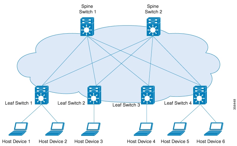
The following image shows a typical spine-leaf topology where four leaf switches are connected through two spine switches:
External connectivity of the VXLAN fabric with other Layer 2 and Layer 3 networks is facilitated through nodes known as border nodes. If the border functionality is established through a spine switch, it is known as a border spine switch. If it is established through a leaf switch, it is known as a border leaf switch.
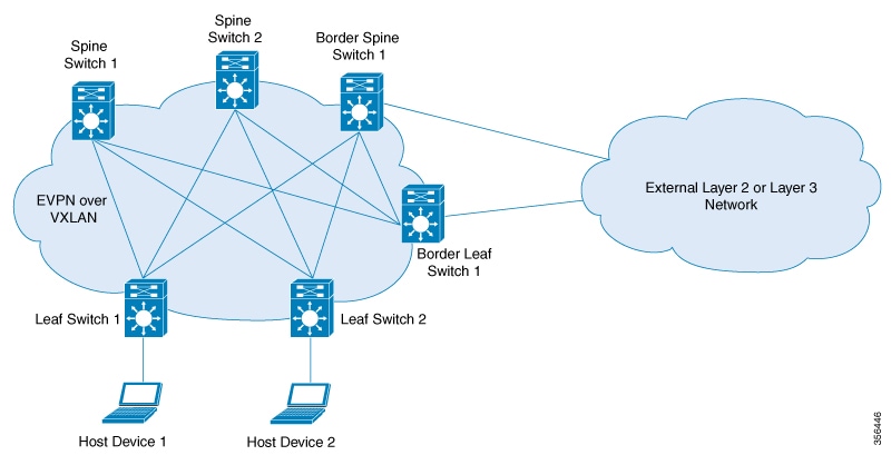
The following image shows a spine-leaf topology with one border leaf switch and one border spine switch connecting the fabric with an external network:
EVPN VXLAN supports Integrated Routing and Bridging (IRB) functionality which allows the VTEPs in a VXLAN network to forward both Layer 2 (bridged) and Layer 3 (routed) traffic. When a VTEP forwards Layer 2 traffic, it is said to be performing bridging. Similarly, when a VTEP forwards Layer 3 traffic, it is said to be performing routing. The traffic between different subnets is forwarded through the VXLAN gateways. IRB is implemented in two ways:
Asymmetric IRB
Symmetric IRB
For more information about IRB, see Information About EVPN VXLAN Integrated Routing and Bridging section.
A VXLAN Gateway is an entity in the network that forwards traffic between VXLAN segments, or from a VXLAN environment to a non-VXLAN environment. Leaf switches in a VXLAN network can function as both Layer 2 and Layer 3 VXLAN gateways.
Layer 2 VXLAN gateways forward traffic within the same VLAN. Layer 2 VXLAN gateways allow VXLAN to VLAN bridging by mapping a VNI segment to a VLAN.
Layer 3 VXLAN gateways forward traffic to a different VLAN. Layer 3 VXLAN gateways allow both VXLAN to VXLAN routing as well as VXLAN to VLAN routing. VXLAN to VXLAN routing provides Layer 3 connectivity between two VNIs where as VXLAN to VLAN routing provides connectivity between a VNI and a VLAN.
The creation of a VXLAN overlay network allows host devices connected to various leaf nodes, that are separated by multiple Layer 3 networks, to interact as if they were connected to a single Layer 2 network, which is the VXLAN segment. This logical Layer 2 segment is called as Layer 2 VNI. The traffic that flows through a Layer 2 VNI between two VLANs within the same subnet is known as bridged traffic.
A VLAN that is locally defined on a VTEP can be mapped to a Layer 2 VNI. In order to allow host devices to connect to a Layer 2 VNI, the connected VLAN must be mapped to the Layer 2 VNI, and then the Layer 2 VNI is associated with the Network Virtualization Edge (NVE) logical interface on the VTEP.
When endpoints connected to a Layer 2 VNI need to communicate with endpoints belonging to different IP subnets, they send the traffic to their default gateway. Communication between endpoints belonging to different Layer 2 VNIs is possible only through a Layer 3 routing function. In an EVPN VXLAN deployment, the various Layer 2 segments that are defined by combining the local VLANs and the global Layer 2 VNIs can be associated to a VRF in order to communicate.
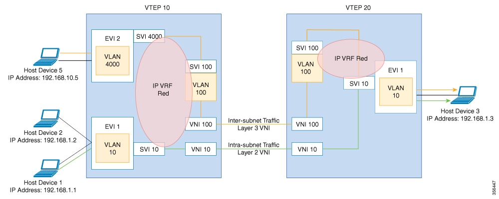
A Layer 3 VNI facilitates Layer 3 segmentation for every VRF on a VTEP. This is done by mapping each VRF instance to a unique Layer 3 VNI in the network and associating the various Layer 2 VNIs for a VTEP to the same VRF. This allows inter- VXLAN communication throughout the Layer 3 VNI within a particular VRF instance. The use of VRFs to enable a logical Layer 3 isolation is known as multi-tenancy. The traffic that flows through a Layer 3 VNI between two VLANs in different subnets is known as routed traffic.
The following image shows the movement of traffic between host devices in same and different subnets through Layer 2 and Layer 3 VNIs:
The identity of an endpoint in the BGP EVPN control plane is derived from its MAC address and IP address, and BGP EVPN provides a mechanism to support endpoint mobility within a VXLAN overlay.
RFC 7432 defines the scope of endpoint mobility within the VXLAN fabric.
A MAC move occurs when an endpoint (or host) moves from one port to another. The new port may be within the same VTEP, or in a different VTEP, in the same VLAN. The BGP EVPN control plane resolves such moves by advertising MAC routes (EVPN route type 2). When an endpoint’s MAC address is learned on a new port, the new VTEP it is in advertises (on the BGP EVPN control plane) that it is the local VTEP for the host. All other VTEPs receive the new MAC route.
A host may move several times, causing the corresponding VTEPs to advertise as many MAC routes. There may also be a delay between the time a new MAC route is advertised and when the old route is withdrawn from the route tables of other VTEPs, resulting in two locations briefly having the same MAC route. Here, a MAC mobility sequence number helps decide the most current of the MAC routes.
When the host MAC address is learned for the first time, the MAC mobility sequence number is set to 0. The value 0 indicates that the MAC address has not had a mobility event, and the host is still at the original location. If a MAC mobility event is detected, a new Route type 2 (MAC or IP advertisement) is added to the BGP EVPN control plane by the new VTEP below which the endpoint moved (its new location). Every time the host moves, the VTEP that detects its new location increments the sequence number by 1 and then advertises the MAC route for that host on the BGP EVPN control plane. On receiving the MAC route at the old location (VTEP), the old VTEP withdraws the old route.
A case may arise in which the same MAC address is simultaneously learned on two different ports. The EVPN control plane detects this condition and alerts the user that there is a duplicate MAC. The duplicate MAC condition may be cleared either by manual intervention, or automatically when the MAC address ages out on one of the ports.
BGP EVPN supports IP mobility in a similar manner to the way it supports MAC mobility. The principal difference is that an IP move is detected when the IP address is learned on a different MAC address, regardless of whether it was learned on the same port or a different port. A duplicate IP address is detected when the same IP address is simultaneously learned on two different MAC addresses, and the user is alerted when this occurs.
 Feedback