Preparing for Installation

Safety Warnings

Safety warnings appear throughout this publication in procedures that may harm you if you perform them incorrectly. A warning symbol precedes each warning statement. The warnings below are general warnings that are applicable to the entire publication.


Warning


Statement 1071—Warning Definition

IMPORTANT SAFETY INSTRUCTIONS

Before you work on any equipment, be aware of the hazards involved with electrical circuitry and be familiar with standard practices for preventing accidents. Read the installation instructions before using, installing, or connecting the system to the power source. Use the statement number at the beginning of each warning statement to locate its translation in the translated safety warnings for this device.

SAVE THESE INSTRUCTIONS


Note


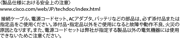
Statement 407—Japanese Safety Instruction

You are strongly advised to read the safety instruction before using the product.

https://www.cisco.com/web/JP/techdoc/pldoc/pldoc.html

When installing the product, use the provided or designated connection cables/power cables/AC adapters.


Warning


To reduce the risk of electric shock, the chassis of this equipment needs to be connected to permanent earth ground during normal use. Statement 0445


Warning


Statement 1008—Class 1 Laser Product

This product is a Class 1 laser product.


Warning


Statement 1017—Restricted Area

This unit is intended for installation in restricted access areas. Only skilled, instructed, or qualified personnel can access a restricted access area.


Warning


Statement 1029—Blank Faceplates and Cover Panels

Blank faceplates and cover panels serve three important functions: they reduce the risk of electric shock and fire, they contain electromagnetic interference (EMI) that might disrupt other equipment, and they direct the flow of cooling air through the chassis. Do not operate the system unless all cards, faceplates, front covers, and rear covers are in place.


Warning


Statement 1047—Overheating Prevention

To prevent the system from overheating, do not operate it in an area that exceeds the maximum recommended ambient temperature of 104°F (40°C).


Warning


Statement 1049—Rack Installation

To reduce the risk of bodily injury, mount the chassis on a rack that is permanently affixed to the building.


Warning


Statement 1055—Class 1/1M Laser

Invisible laser radiation is present. Do not expose to users of telescopic optics. This applies to Class 1/1M laser products.


Warning


Statement 1056—Unterminated Fiber Cable

Invisible laser radiation may be emitted from the end of the unterminated fiber cable or connector. Do not view directly with optical instruments. Viewing the laser output with certain optical instruments, for example, eye loupes, magnifiers, and microscopes, within a distance of 100 mm, may pose an eye hazard.


Warning


Statement 1090—Installation by Skilled Person

Only a skilled person should be allowed to install, replace, or service this equipment. See statement 1089 for the definition of a skilled person.

There are no serviceable parts inside. To avoid risk of electric shock, do not open.


Warning


Statement 1074—Comply with Local and National Electrical Codes

To reduce risk of electric shock or fire, installation of the equipment must comply with local and national electrical codes.


Warning


Statement 1089—Instructed and Skilled Person Definitions

An instructed person is someone who has been instructed and trained by a skilled person and takes the necessary precautions when working with equipment.

A skilled person or qualified personnel is someone who has training or experience in the equipment technology and understands potential hazards when working with equipment.

There are no serviceable parts inside. To avoid risk of electric shock, do not open.


Warning


Statement 1091—Installation by an Instructed Person

Only an instructed person or skilled person should be allowed to install, replace, or service this equipment. See statement 1089 for the definition of an instructed or skilled person.

There are no serviceable parts inside. To avoid risk of electric shock, do not open.


Warning


Statement 1099—Before Connecting to System Power Supply

High touch/leakage current—Permanently connected protective earth ground is essential before connecting to the system power supply.


Warning


Statement 9001—Product Disposal

Ultimate disposal of this product should be handled according to all national laws and regulations.


SFP and QSFP Module Ports


Note


With the C9600X-LC-56YL4C model:

  • Do not use the SFP-H10GB-CUXX (1M/1.5M/2M/2.5M/3M/5M), SFP-H10GB-ACUXX(7M/10M) and SFP-10G-AOCXX (1M/2M/3M/5M/7M/10M) types of SFP modules from TE Connectivity, because the lever on these modules might interfere with other parts of the switch.

  • On an SFP-10G-T-X SFP module, do not use an RJ-45 cable with a protection cap because the protruding cap might interfere with other parts of the switch.

  • Do not use the SFP-25G-SR-S, SFP-10/25G-LR-S, SFP-10/25G-CSR-S on row C, the SFP module will be removed from the SFP port, if the lower card (underneath this card) is removed from the chassis of C9600.


Site Requirements

Planning a proper location for the switch and layout of the equipment rack or wiring closet is essential for successful system operation. These sections describe some of the basic site requirements that you should be aware of as you prepare to install your switch, including the following:

  • Environmental factors can adversely affect the performance and longevity of your system.

  • Install the switch in an enclosed, secure area, ensuring that only qualified personnel have access to the switch and control of the environment.

  • Equipment that is placed too closely together or that is inadequately ventilated may cause system over-temperature conditions, leading to premature component failure.

  • Poor equipment placement can make chassis panels inaccessible and difficult to maintain.

  • The switch requires a dry, clean, well-ventilated, and air-conditioned environment.

  • To ensure normal operation, maintain ambient airflow. If the airflow is blocked or restricted, or if the intake air is too warm, an over-temperature condition may occur. The switch environmental monitor may then shut down the system to protect the system components.

  • Multiple switches can be rack mounted with little or no clearance above and below the chassis. However, when mounting a switch in a rack with other equipment, or when placing it on the floor near other equipment, ensure that the exhaust from other equipment does not blow into the air intake vent of the switch chassis.

Temperature

Temperature extremes may cause a system to operate at reduced efficiency and cause a variety of problems, including premature aging and failure of chips, and failure of mechanical devices. Extreme temperature fluctuations may also cause chips to become loose in their sockets. Observe the following guidelines:

  • Ensure that the system is operating in an environment that is:

    • 23 to 104 °F (-5 to 40 °C) up to 6000 feet (1800m)

    • 23 to 104 °F (-5 to 40 °C) up to 10000 feet (3000m)

  • Ensure that the chassis has adequate ventilation.

  • Do not place the chassis within a closed-in wall unit or on top of cloth, which can act as thermal insulation.

  • Do not place the chassis where it will receive direct sunlight, particularly in the afternoon.

  • Do not place the chassis next to a heat source of any kind, including heating vents.

  • Adequate ventilation is particularly important at high altitudes. Make sure that all the slots and openings on the system remain unobstructed, especially the fan vent on the chassis.

  • Clean the installation site at regular intervals to avoid buildup of dust and debris, which may cause a system to overheat.

  • If system is exposed to abnormally low temperatures, allow a two hour warm up period, in ambient temperature no lower than 32°F (0 °C) before turning on.


Caution


You have 2 minutes to replace fan tray. If one fans in the fan tray is not functioning, the system can function; however, you must replace the fan tray as soon as possible.


Failure to observe these guidelines may damage the chassis' internal components.

Air Flow

The switch is designed to be installed in an environment where there is a sufficient volume of air available to cool the supervisor engines, modules, and power supplies. If there are any constraints with regard to the free flow of air through the chassis, or if the ambient air temperature is elevated, the switch environmental monitor may then shut down the system to protect the system components.

To maintain proper air circulation through the switch chassis, we recommend that you maintain a minimum space of 6 inches (15 cm) between a wall and the chassis and power supply unit air intakes or a wall and the chassis and power supply unit hot air exhausts. In situations where the switch chassis are installed in adjacent racks, you should allow a minimum space of 12 inches (30.5 cm) between the air intake of one chassis and the hot air exhaust of another chassis.


Note


Failure to maintain adequate spacing between chassis may cause the switch chassis that is drawing in the hot exhaust air to overheat and fail.


Figure 1. Air Flow Direction - Cisco Catalyst 9600 Series Switches


1

Chassis air intake

3

Chassis air exhaust

2

Power supply air intake

4

Power supply air exhaust

If you are installing your switch in an enclosed or partially enclosed rack, we strongly recommend that you verify that your site meets the following guidelines:

  • Verify that there is a minimum of 6 inches (15 cm) of clearance between the sides, front, and back of any enclosure, and both the chassis air intake grill and the chassis air exhaust grill along with the power supply unit intakes and exhausts. The upright columns of a relay rack may be located less than the recommended side spacing provided there are substantial cutouts, holes, or vents in the structure to allow adequate air flow through the chassis.

  • Verify that the ambient air temperature within the enclosed or partially enclosed rack is within the chassis operating temperature limits. After installing the chassis in the rack, power up the chassis and allow the chassis temperature to stabilize (approximately 2 hours).

    Measure the ambient air temperature at the chassis air intake grill by positioning an external temperature probe 1 inch (2.5 cm) away from the chassis left side, and centered on the chassis both horizontally and vertically.

    Measure the ambient air temperature at the power supply unit air intake grill by positioning an external temperature probe 1 inch (2.5 cm) away from the chassis front, centered on the power supply unit section located above the card slots.

    • If the ambient intake air temperature is less than 113°F (45°C) at altitudes of 6,000 feet and below, the rack meets the intake air temperature criterion. At altitudes above that threshold and up to 10,000 feet (3000 m), the air intake should not exceed 104°F (40°C).

    • If the ambient intake air temperature exceeds this recommendation, the system may experience minor temperature alarms and increase fan speeds in response.

    • If the ambient intake air temperature equals or is greater than 131°F (55°C), the system may experience a major temperature alarm with maximum fan speeds in response. If ambient temperature continues to increase, system will respond with protective shut down.

  • Plan ahead. A switch that is currently installed in an enclosed or partially enclosed rack might meet ambient air temperature and air flow requirements at present. However, if you add more chassis to the rack or more modules to a chassis in the rack, the additional heat generated might cause the ambient air temperature at the chassis or power supply unit inlets to exceed recommended conditions which may trigger thermal alarms.

Humidity

High-humidity conditions may cause moisture to enter the system, and cause corrosion of internal components and degradation of properties such as electrical resistance, thermal conductivity, physical strength, and size. Extreme moisture buildup inside the system may result in electrical short circuit, which may cause serious damage to the system. Each system is rated for storage and operation in 10 to 95 percent relative humidity, non-condensing with a humidity gradation of 10 percent per hour. Buildings in which climate is controlled by air-conditioning in the warmer months and by heat during the colder months usually maintain an acceptable level of humidity for system equipment. However, if a system is located in an unusually humid location, a dehumidifier should be used to maintain the humidity within an acceptable range.

Altitude

Operating a system at high altitude (low pressure) reduces the efficiency of forced and convection cooling and may result in electrical problems related to arcing and corona effects. This condition may also cause sealed components with internal pressure, such as electrolytic capacitors, to fail or perform at reduced efficiency.

Dust and Particles

Fans cool power supplies and system components by drawing in room-temperature air and exhausting heated air out through various openings in the chassis. However, fans also ingest dust and other particles, causing contaminant buildup in the system and increased internal chassis temperature. A clean operating environment can greatly reduce the negative effects of dust and other particles, which act as insulators and interfere with the mechanical components in the system.

The standards listed below provide guidelines for acceptable working environments and acceptable levels of suspended particulate matter:

  • National Electrical Manufacturers Association (NEMA) Type 1

  • International Electrotechnical Commission (IEC) IP-20

Air Quality

Dust is everywhere and often invisible to the naked eye. It consists of fine particles in the air that originate from various sources, such as soil dust lifted by weather, from volcanic eruptions, or pollution. Dust at an installation site may contain small amounts of textile, paper fibers, or minerals from outdoor soil. It may also contain natural contaminants, such as chlorine from the marine environment and industrial contaminants such as sulfur. Ionized dust and debris are dangerous and get attracted to electronic equipment.

The accumulation of dust and debris on electronic equipment has the following adverse effects:

  • It increases the operating temperature of the equipment. According to the Arrhenius effect, an increase in the operating temperature leads to a decrease in reliability and life of the equipment.

  • The moisture and corrosive elements that are present in the dust can corrode the electronic or mechanical components and cause premature board failure.

These adverse effects are further accelerated by the presence of fans in the data networking equipment that ingest dust and other particles into the equipment. Higher the volume of air that is generated by the fans for cooling, the higher the quantity of dust and particulates that get deposited and trapped inside the equipment. Remove or minimize the presence of dust and particulates at the installation site by following the guidelines mentioned in ANSI 71-04-2013 regulations.


Note


In addition to the guidelines mentioned in ANSI 71-04-2013 regulations, follow all applicable guidelines as per site conditions to remove or minimize other contaminants.


Corrosion

Corrosion is a chemical reaction that occurs between electronic components and gases which results in metal deterioration. Corrosion attacks edge connectors, pin connectors, IC plug-in sockets, wirewraps, and all other metal components. Depending on the type and concentration level of the corrosive gases, performance degradation of the components occurs either rapidly or over a period of time. It also leads to blocked currents, brittle connection points, and overheated electrical systems. Corrosion by-products form insulating layers on circuits and causes electronic failure, short circuits, pitting, and metal loss.

A type of corrosion known as creep corrosion, that primarily affects PCBA (Printed Circuit Board Assembly) occurs when the PCBA is subjected to a harsh, and sulfur-rich (hydrogen sulfide) end-use environment over a prolonged period of time. The corrosion begins on certain exposed metals, such as copper and silver, and then creeps along the remaining metal surface either causing electrical short circuits or creating holes. Creep corrosion also occurs on electronic components such as resistors and PCBs.

To prevent corrosion, remove or minimize the presence of dust and particulates at the installation site by following the guidelines mentioned in ANSI 71-04-2013 regulations.

Figure 2. A PCB with Corrosion on its Metal Contacts

EMI and Radio Frequency Interference

Electro-Magnetic interference (EMI) and radio frequency interference (RFI) from a system can adversely affect devices such as radio and television (TV) receivers operating near the system. Radio frequencies emanating from a system can also interfere with cordless and low-power telephones. Conversely, RFI from high-power telephones can cause spurious characters to appear on the system monitor. RFI is defined as any EMI with a frequency above 10 kilohertz (kHz). This type of interference can travel from the system to other devices through the power cable and power source, or through the air in the form of transmitted radio waves. The Federal Communications Commission (FCC) publishes specific regulations to limit the amount of harmful interference emitted by computing equipment. Each system meets these FCC regulations. To reduce the possibility of EMI and RFI, follow these guidelines:

  • Always operate the system with the chassis covers installed.

  • Ensure that all chassis slots are covered by a metal filler bracket and that an unused power supply bay has a metal cover plate installed.

  • Ensure that the screws on all peripheral cable connectors are securely fastened to their corresponding connectors on the back of the chassis.

  • Always use shielded cables with metal connector shells for attaching peripherals to the system.

When wires are run for any significant distance in an electromagnetic field, interference can occur between the field and the signals on the wires. This fact has two implications for the construction of plant wiring:

  • Bad wiring practice can result in radio interference emanating from the plant wiring.

  • Strong EMI, especially when it is caused by lightning or radio transmitters, can destroy the signal drivers and receivers in the chassis, and even create an electrical hazard by conducting power surges through lines into equipment.


Note


To predict and provide a remedy for strong EMI, consult experts in RFI.


If you use twisted-pair cable in your plant wiring, include a good distribution of grounding conductors to reduce EMI. If you exceed the recommended distances, use a high-quality twisted-pair cable with one ground conductor for each data signal when applicable.


Caution


Category 5e, Category 6, and Category 6a cables can store large levels of static electricity because of the dielectric properties of the materials used in their construction. Always ground the cables (especially in new cable runs) to a suitable and safe earth ground before connecting them to the module.


If the wires exceed the recommended distances, or if wires pass between buildings, give special consideration to the effect of a lightning strike in your vicinity. The electromagnetic pulse caused by lightning or other high-energy phenomena can easily couple enough energy into unshielded conductors to destroy electronic devices. If you have had problems of this sort in the past, you may want to consult experts in electrical surge suppression and shielding.


Caution


The intra-building ports (Copper-Based Ethernet Ports) of the equipment or subassembly is suitable for connection to inside a building or unexposed wiring or cabling only. If the intra-building ports of the equipment or subassembly is metalically connected to interfaces that connect to the Out Side Plant (OSP) or its wiring, the metallic-connection MUST NOT be more than 6 meters (approximately 20 feet). These interfaces are designed for use as intra-building interfaces only (Type 2, 4, or 4a ports as described in GR-1089-CORE) and require isolation from the exposed OSP cabling. The addition of Primary Protectors is not sufficient protection in order to connect these interfaces metallically to an OSP wiring system.


Shock and Vibration

The equipment complies with the Earthquake, Office, and Transportation Vibration, and Equipment Handling Criteria of GR-63-CORE.

Power Source Interruptions

Systems are especially sensitive to variations in voltage supplied by the AC power source. Overvoltage, undervoltage, and transients (or spikes) can erase data from memory or even cause components to fail. To protect against these types of problems, power wiring ground conductors should always be properly grounded. Also, place the system on a dedicated power circuit (rather than sharing a circuit with other heavy electrical equipment). In general, do not allow the system to share a circuit with any of the following:

  • Copy machines

  • Air conditioners

  • Vacuum cleaners

  • Space heaters

  • Power tools

  • Teletype machines

  • Laser printers

  • Facsimile machines

  • Any other motorized equipment

Besides these appliances, the greatest threats to a system's power supply are surges or blackouts that are caused by electrical storms. Whenever possible, turn off the system and peripherals, if any, and unplug them from their power sources during thunderstorms. If a blackout occurs—even a temporary one—while the system is turned on, turn off the system immediately and disconnect it from the electrical outlet. Leaving the system on may cause problems when the power is restored; all other appliances left on in the area may create large voltage spikes that may damage the system.

System Grounding


Warning


Statement 1046—Installing or Replacing the Unit

To reduce risk of electric shock, when installing or replacing the unit, the ground connection must always be made first and disconnected last.

If your unit has modules, secure them with the provided screws.


You must install a system ground as part of the chassis installation process. Chassis installations that rely only on the AC third-prong ground are insufficient to adequately ground the systems.

Proper grounding practices ensure that the buildings and the installed equipment within them have low-impedance connections and low-voltage differentials between chassis. When you install a system ground, you reduce or prevent shock hazards, chances of equipment damage due to transients, and the potential for data corruption.

Without proper and complete system grounding, you run the risk of increased component damage due to ESD. Additionally, you have a greatly increased chance of data corruption, system lockup, and frequent system reboot situations by not using a system ground.


Caution


Installations that rely solely on system grounding that uses only an AC third-prong ground run a substantially greater risk of equipment problems and data corruption than those installations that use both the AC third-prong ground and a properly installed system ground.

The following table lists some general grounding practice guidelines.

Table 1. Grounding Practice Guidelines

Environment

Electromagnetic Noise Severity Level

Grounding Recommendations

Commercial building is subjected to direct lightning strikes.

For example, some places in the United States, such as Florida, are prone to more lightning strikes than other areas.

High

All lightning protection devices must be installed in strict accordance with manufacturer recommendations. Conductors carrying lightning current should be spaced away from power and data lines in accordance with applicable recommendations and building codes. Best grounding practices must be closely followed.

Commercial building is located in an area where lightning storms occur frequently, but is not prone to direct lightning strikes.

High

Best grounding practices must be closely followed.

Commercial building contains a mix of information technology equipment and industrial equipment, such as welding.

Medium to High

Best grounding practices must be closely followed.

Existing commercial building is not subject to natural environmental noise or man-made industrial noise. This building contains a standard office environment. This installation has a history of malfunction due to electromagnetic noise.

Medium

Best grounding practices must be closely followed. Determine source and cause of noise if possible, and mitigate as closely as possible at the noise source or reduce coupling from the noise source to the victim equipment.

New commercial building is not subject to natural environmental noise or man-made industrial noise. This building contains a standard office environment.

Low

Best grounding practices should be followed as closely as possible. Electromagnetic noise problems are not anticipated, but installing a best-practice grounding system in a new building is often the least expensive route, and the best way to plan for the future.

Existing commercial building is not subject to natural environmental noise or man-made industrial noise. This building contains a standard office environment.

Low

Best grounding practices should be followed as much as possible. Electromagnetic noise problems are not anticipated, but installing a best-practice grounding system is always recommended.


Note


In all situations, grounding practices must comply with Section 250 of the National Electric Code (NEC) requirements or local laws and regulations. A 6 AWG grounding wire is preferred from the chassis to the rack ground or directly to the common bonding network (CBN). The equipment rack should also be connected to the CBN with a 6 AWG grounding wire.

Note


Grounding lugs must be installed on the location marked on the chassis only.

Note


Always ensure that all of the modules are completely installed and that the captive installation screws are fully tightened. In addition, ensure that all the I/O cables and power cords are properly seated. These practices are normal installation practices and must be followed in all installations.

Caution


Category 5e, Category 6, and Category 6a cables can store large levels of static electricity because of the dielectric properties of the materials used in their construction. Always ground the cables (especially in new cable runs) to a suitable and safe earth ground before connecting them to the module.

Maintaining Safety with Electricity

When working on electrical equipment, follow these guidelines:

  • Do not work alone if potentially hazardous conditions exist anywhere in your work space.

  • Never assume that power is disconnected from a circuit; always check the circuit before working on it.

  • When the power is switched off, put a lock-box on the circuit, so that no one can accidentally switch it on.

  • Look carefully for possible hazards in your work area, such as damp floors, ungrounded power extension cables, frayed or damaged power cords, and missing safety grounds.

  • If an electrical accident occurs, proceed as follows:

    • Use extreme caution; do not become a victim yourself.

    • Disconnect power from the system.

    • Seek medical attention, if necessary.

  • Use the product within its marked electrical ratings and product usage instructions.

  • Install the product in compliance with local and national electrical codes.

  • If any of the following conditions occur, contact the Cisco Technical Assistance Center:

    • The power cable or plug is damaged.

    • An object has fallen into the product.

    • The product has been exposed to water or other liquids.

    • The product has been dropped or shows signs of damage.

    • The product does not operate correctly when you follow the operating instructions.

  • Use the correct external power source. Operate the product only from the type of power source indicated on the electrical ratings label. If you are not sure of the type of power source required, consult a local electrician.

  • Use approved power cables only. You have been provided with one or more power cables with your chassis power supply that are intended for use in your country, based on the shipping location. Should you need to purchase additional power cables, ensure that they are rated for the product and for the voltage and current marked on the product’s electrical ratings label. The voltage and current rating of the power cable should be greater than the ratings marked on the label.

  • To help prevent electrical shock, plug all the power cables into properly grounded electrical outlets. These power cables are equipped with three-prong plugs to ensure proper grounding. Do not use adapter plugs or remove the grounding prong from a power cable.

  • Observe power strip ratings. Make sure that the total current rating of all products that are plugged into the power strip does not exceed 80 percent of the power strip rating.

  • Do not modify power cables or plugs yourself. Consult with a licensed electrician or your power company for site modifications. Always follow your local and national wiring codes.

Preventing ESD Damage

ESD damage might occur when modules or other FRUs are improperly handled, resulting in intermittent or complete failure of the modules or FRUs. Modules consist of printed circuit boards that are fixed in metal carriers. EMI shielding and connectors are integral components of a carrier. Although the metal carrier helps to protect the board from ESD, always use an ESD-grounding strap when handling modules. To prevent ESD damage, follow these guidelines:

  • Always use an ESD wrist or ankle strap and ensure that it makes good skin contact.

  • Connect the equipment end of the strap to an unfinished chassis surface.

  • When installing a component, use an available ejector lever to properly seat the bus connectors in the backplane or midplane. These devices prevent accidental removal, provide proper grounding for the system, and help to ensure that bus connectors are properly seated.

  • When removing a component, use an available ejector lever to release the bus connectors from the backplane or midplane.

  • Handle carriers by available handles or edges only; avoid touching the printed circuit boards or connectors.

  • Place a removed component board-side-up on an antistatic surface or in a static-shielding container. If you plan to return the component to the factory, immediately place it in a static-shielding container.

  • Avoid contact between the printed circuit boards and clothing. The wrist strap only protects components from ESD voltages on the body; ESD voltages on clothing can still cause damage.

  • Never attempt to remove the printed circuit board from the metal carrier.

Power Requirements

Power supplies installed on the switch chassis can be all AC-input, all DC-input, or a mix of both. When preparing your site for switch installation, adhere to these requirements:

  • In systems configured with more than one power supply, connect each of the power supplies to a separate input power source. If you fail to do this, your system might be susceptible to total power failure due to a fault in the external wiring or a tripped circuit breaker

  • To prevent loss of input power, be sure that the total maximum load on each source circuit is within the current ratings of the wiring and breakers.

  • In some systems, you may decide to use an uninterrupted power supply (UPS) to protect against power failures at your site. Be aware when selecting a UPS that some UPS models that use ferroresonant technology may become unstable when operating with the switch power supplies that use power factor correction. This may cause the output voltage waveform to the switch to become distorted, resulting in an undervoltage situation in the system.

Cabling Requirements

When running power and data cables together in overhead cable trays or subfloor cable trays, be aware of the following caution:


Caution


We strongly recommend that power cabling runs and other potential noise sources be located as far away as practical from LAN cabling that terminates on Cisco equipment. In situations where this type of long parallel cable runs exist and cannot be separated by at least 3.3 feet (1 meter), we recommend that you shield these potential noise sources. To avoid interference, the source should be shielded by housing it in a grounded metallic conduit.


Also be aware of the following caution concerning the use of Category 5e and Category 6 Ethernet cables:


Caution


Category 5e, Category 6, and Category 6a cables can store large levels of static electricity because of the dielectric properties of the materials used in their construction. Always ground the cables (especially in new cable runs) to a suitable and safe earth ground before connecting them to the module.


Rack-Mounting Guidelines

Rack Specifications

Cisco Catalyst 9600 Series Switches are designed to be installed in standard, 19-inch equipment racks that meet EIA-310-D specifications. In Network Equipment Building Systems (NEBS) compliant installation, you can use only a 23-inch rack mount. Before rack-mounting the chassis, ensure that the equipment rack complies with all requirements and guidelines

Mounting Location Guidelines

Cisco Catalyst 9600 Series Switches must be front-mounted.

Accordingly, you can install the chassis in 2-post or 4-post racks, but in a 4-post rack, the rear posts are not used for mounting.

Width and Depth Requirements

Use a tape measure to verify the interior dimensions of the rack.

  • Measure the space between the inner edges of the left front and right front mounting posts. The chassis is 19 inches (48.26 cm) wide and must fit between the mounting posts.

  • Measure the depth of the rack from the outside of the front mounting posts to the outside of the rear mounting strip. The chassis is 18.8 inches (47.75 cm) deep.

Height Requirements

The rack must have sufficient clearance in terms of height, to insert the chassis. Chassis height is also measured in rack units (RU or just U) where 1 RU or 1 U equals 1.75 inches (44.45 mm). A typical server rack is 42 RU or 42 U in height.

The chassis height of Catalyst 9606R Switch is 8 RU with a depth of 18.8 inches.

Other General Guidelines


Caution


If the equipment rack is on wheels, ensure that the brakes are engaged and that the rack is stabilized.

Warning


To prevent bodily injury when mounting or servicing this unit in a rack, you must take special precautions to ensure that the system remains stable. The following guidelines are provided to ensure your safety:

  • This unit should be mounted at the bottom of the rack if it is the only unit in the rack.

  • When mounting this unit in a partially filled rack, load the rack from the bottom to the top with the heaviest component at the bottom of the rack.

  • If the rack is provided with stabilizing devices, install the stabilizers before mounting or servicing the unit in the rack. Statement 1006


Warning


Take care when connecting units to the supply circuit so that wiring is not overloaded. Statement 1018


Note


To maintain proper air circulation through the switch chassis, we recommend that you maintain a minimum space of 6 inches (15 cm) between a wall and the chassis and power supply unit air intakes or a wall and the chassis and power supply unit hot air exhausts. In situations where the switch chassis are installed in adjacent racks, you should allow a minimum space of 12 inches (30.5 cm) between the air intake of one chassis and the hot air exhaust of another chassis. Failure to maintain adequate spacing between chassis may cause the switch chassis that is drawing in the hot exhaust air to overheat and fail.

Site Preparation Checklist

The following table lists the site-planning activities that you should perform prior to installing the switch. Completing each activity helps ensure a successful switch installation.
Table 2. Site Preparation Checklist

Task No.

Activity

Verified By

Time

Date

1

Space evaluation

  • Space and layout

  • Floor covering

  • Impact and vibration

  • Lighting

  • Maintenance access

2

Environmental evaluation

  • Ambient temperature

  • Humidity

  • Altitude

  • Atmospheric contamination

  • Airflow

3

Power evaluation

  • Input power type

  • Power receptacles (Depends on power supply)1

  • Receptacle proximity to the equipment.

  • Dedicated (separate) circuits for redundant power supplies.

  • UPS for power failures2

4

Grounding evaluation

  • Circuit breaker size

  • CO ground (AC powered systems)

5

Cable and interface equipment evaluation

  • Cable type

  • Connector type

  • Cable distance limitations

  • Interface equipment (transceivers)

  • Cable bundling sizes

6

EMI evaluation

  • Distance limitations for signaling

  • Site wiring

  • RFI levels

1 Verify that each power supply installed in the chassis has a dedicated AC source circuit.
2 Refer to the power supply'VA rating as a sizing criterion in determining the output required by the UPS. The power supply kVA rating value is listed in the specifications table for each power supply in Appendix A (power supply specifications).