Configuring NHRP

Information About Next Hop Resolution Protocol

The following sections provide information about Next Hop Resolution Protocol (NHRP).

NHRP and NBMA Network Interaction

Most WAN networks are a collection of point-to-point links. Virtual tunnel networks (for example Generic Routing Encapsulation [GRE] tunnels) are also a collection of point-to-point links. To effectively scale the connectivity of these point-to-point links, they are usually grouped into a single or multilayer hub-and-spoke network. Multipoint interfaces (for example, GRE tunnel interfaces) can be used to reduce the configuration on a hub router in such a network. This resulting network is a NBMA network.

Because there are multiple tunnel endpoints that are reachable through a single multipoint interface, there needs to be a mapping from the logical tunnel endpoint IP address to the physical tunnel endpoint IP address, to forward packets out of the tunnel interfaces over this NBMA network. This mapping could be statically configured, but it is preferable if the mapping can be discovered or learned dynamically.

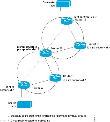
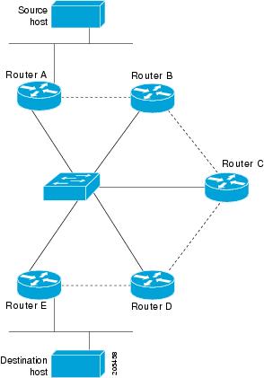
NHRP is an ARP-like protocol that alleviates these NBMA network problems. With NHRP, systems attached to an NBMA network dynamically learn the NBMA address of other systems that are part of the network, allowing these systems to directly communicate without requiring traffic to use an intermediate hop.

Routers, access servers, and hosts can use NHRP to discover the addresses of other routers and hosts connected to an NBMA network. Partially-meshed NBMA networks typically have multiple logical networks behind the NBMA network. In such configurations, packets traversing the NBMA network might have to make several hops over the NBMA network before arriving at the exit router (the router nearest the destination network).

NHRP Registration helps support these NBMA networks:

  • NHRP Registration—NHRP allows Next Hop Clients (NHCs) to dynamically register with Next Hop Servers (NHSs). This registration function allows the NHCs to join the NBMA network without configuration changes on the NHSs, especially in cases where the NHC has a dynamic physical IP address or is behind a Network Address Translation (NAT) router that dynamically changes the physical IP address. In these cases, it would be impossible to preconfigure the logical (VPN IP address) to physical (NBMA IP) mapping for the NHC on the NHS.

Dynamically Built Hub-and-Spoke Networks

With NHRP, the NBMA network is initially laid out as a hub-and-spoke network that can have multiple hierarchical layers of NHCs as spokes and NHSs as hubs. The NHCs are configured with static mapping information to reach their NHSs and will connect to their NHS and send an NHRP registration to the NHS. This configuration allows the NHS to dynamically learn the mapping information for the spoke, reducing the configuration needed on the hub and allowing the spoke to obtain a dynamic NBMA (physical) IP address.

How to Configure Next Hop Resolution Protocol

The following sections provide configuration information about NHRP.

Enabling NHRP on an Interface

Perform this task to enable NHRP for an interface on a switch. In general, all NHRP stations within a logical NBMA network should be configured with the same network identifier.

The NHRP network ID is used to define the NHRP domain for an NHRP interface and differentiate between multiple NHRP domains or networks, when two or more NHRP domains (GRE tunnel interfaces) are available on the same NHRP node (switch). The NHRP network ID helps keep two NHRP networks (clouds) separate when both are configured on the same switch.

The NHRP network ID is a local-only parameter. It is significant only to the local switch and is not transmitted in NHRP packets to other NHRP nodes. For this reason the actual value of the NHRP network ID configured on a switch need not match the same NHRP network ID on another switch where both of these switches are in the same NHRP domain. As NHRP packets arrive on a GRE interface, they are assigned to the local NHRP domain in the NHRP network ID that is configured on that interface.

We recommend that the same NHRP network ID be used on the GRE interfaces on all switches that are in the same NHRP network. It is then easier to track which GRE interfaces are members of which NHRP network.

NHRP domains (network IDs) can be unique on each GRE tunnel interface on a switch. NHRP domains can span across GRE tunnel interfaces on a route. In this case the effect of using the same NHRP network ID on the GRE tunnel interfaces is to merge the two GRE interfaces into a single NHRP network.

Procedure

  Command or Action Purpose

Step 1

enable

Example:


Switch> enable

Enables privileged EXEC mode.

  • Enter your password if prompted.

Step 2

configure terminal

Example:


Switch# configure terminal

Enters global configuration mode.

Step 3

interface type number

Example:


Switch(config)# interface tunnel 100

Configures an interface and enters interface configuration mode.

Step 4

ip address ip-address network-mask

Example:


Switch(config-if)# ip address 10.0.0.1 255.255.255.0

Enables IP and gives the interface an IP address.

Step 5

ip nhrp network-id number

Example:


Switch(config-if)# ip nhrp network-id 1

Enables NHRP on the interface.

Step 6

end

Example:


Switch(config)# end

Exits interface configuration mode and returns to privileged EXEC mode.

Configuring a GRE Tunnel for Multipoint Operation

Perform this task to configure a GRE tunnel for multipoint (NMBA) operation.

A tunnel network of multipoint tunnel interfaces can be considered of as an NBMA network. When multiple GRE tunnels are configured on the same switch, they must either have unique tunnel ID keys or unique tunnel source addresses.

Procedure

  Command or Action Purpose

Step 1

enable

Example:

Switch> enable

Enables privileged EXEC mode.

  • Enter your password if prompted.

Step 2

configure terminal

Example:


Switch# configure terminal

Enters global configuration mode.

Step 3

interface type number

Example:


Switch(config)# interface tunnel 100

Configures an interface and enters interface configuration mode.

Step 4

ip address ip-address

Example:


Switch(config-if)# ip address 172.16.1.1 255.255.255.0

Configures an IP address for the interface.

Step 5

ip mtu bytes

Example:


Switch(config-if)# ip mtu 1400

Sets the maximum transmission unit (MTU) size of IP packets sent on an interface.

Step 6

ip pim sparse-dense-mode

Example:


Switch(config-if)# ip pim sparse-dense-mode

Enables Protocol Independent Multicast (PIM) on an interface and treats the interface in either sparse mode or dense mode of operation, depending on which mode the multicast group operates in.

Step 7

ip nhrp map ip-address nbma-address

Example:


Switch(config-if)# ip nhrp map 172.16.1.2 10.10.10.2

Statically configures the IP-to-nonbroadcast multiaccess (NBMA) address mapping of IP destinations connected to an NBMA network.

  • ip-address —IP address of the destinations reachable through the NBMA network. This address is mapped to the NBMA address.

  • nbma-address —NBMA address that is directly reachable through the NBMA network. The address format varies depending on the medium used. For example, ATM has a Network Service Access Point (NSAP) address, Ethernet has a MAC address, and Switched Multimegabit Data Service (SMDS) has an E.164 address. This address is mapped to the IP address.

Step 8

ip nhrp map multicast nbma-address

Example:


Switch(config-if)# ip nhrp map multicast 10.10.10.2

Configures nonbroadcast multiaccess (NBMA) addresses used as destinations for broadcast or multicast packets to be sent over a tunnel network.

Step 9

ip nhrp network-id number

Example:


Switch(config-if)# ip nhrp network-id 1

Enable the Next Hop Resolution Protocol ( NHRP) on an interface.

  • number —Globally unique, 32-bit network ID from a nonbroadcast multiaccess (NBMA) network. The range is from 1 to 4294967295.

Step 10

ip nhrp nhs nhs-address

Example:


Switch(config-if)# ip nhrp nhs 172.16.1.2

Specifies the address of one or more NHRP servers.

  • nhs-address —Address of the next-hop server being specified.

Step 11

tunnel source vlan interface-number

Example:


Switch(config-if)# tunnel source vlan 1

Sets the source address for a tunnel interface

Step 12

tunnel destination ip-address

Example:


Switch(config-if)# tunnel destination 10.10.10.2

Sets the destination address for a tunnel interface.

Step 13

end

Example:


Switch(config-if)# end

Exits interface configuration mode and returns to privileged EXEC mode.

Configuration Examples for Next Hop Resolution Protocol

The following sections provide various configuration examples for NHRP.

Physical Network Designs for Logical NBMA Examples

A logical NBMA network is considered the group of interfaces and hosts participating in NHRP and having the same network identifier. The figure below illustrates two logical NBMA networks (shown as circles) configured over a single physical NBMA network. Router A can communicate with routers B and C because they share the same network identifier (2). Router C can also communicate with routers D and E because they share network identifier 7. After address resolution is complete, router A can send IP packets to router C in one hop, and router C can send them to router E in one hop, as shown by the dotted lines.

Figure 1. Two Logical NBMA Networks over One Physical NBMA Network
The figure illustrates two logical NBMA networks configured over a single physical NBMA network.

The physical configuration of the five routers in the figure above might actually be that shown in the figure below. The source host is connected to router A and the destination host is connected to router E. The same switch serves all five routers, making one physical NBMA network.

Figure 2. Physical Configuration of a Sample NBMA Network
The figures shows the physical configuration of a sample NBMA network.

Refer again to the first figure above. Initially, before NHRP has resolved any NBMA addresses, IP packets from the source host to the destination host travel through all five routers connected to the switch before reaching the destination. When router A first forwards the IP packet toward the destination host, router A also generates an NHRP request for the IP address of the destination host. The request is forwarded to router C, whereupon a reply is generated. Router C replies because it is the egress router between the two logical NBMA networks.

Similarly, router C generates an NHRP request of its own, to which router E replies. In this example, subsequent IP traffic between the source and the destination still requires two hops to traverse the NBMA network, because the IP traffic must be forwarded between the two logical NBMA networks. Only one hop would be required if the NBMA network were not logically divided.

Example: GRE Tunnel for Multipoint Operation

With multipoint tunnels, a single tunnel interface may be connected to multiple neighboring switches. Unlike point-to-point tunnels, a tunnel destination need not be configured. In fact, if configured, the tunnel destination must correspond to an IP multicast address.

In the following example, switches A and B share an Ethernet segment. Minimal connectivity over the multipoint tunnel network is configured, thus creating a network that can be treated as a partially meshed NBMA network. Due to the static NHRP map entries, switch A knows how to reach switch B and vice versa.

The following example shows how to configure a GRE multipoint tunnel:

Switch A Configuration


Switch(config)# interface tunnel 100 !Tunnel interface configured for PIM traffic
Switch(config-if)# no ip redirects
Switch(config-if)# ip address 192.168.24.1 255.255.255.252
Switch(config-if)# ip mtu 1400
Switch(config-if)# ip pim sparse-dense-mode
Switch(config-if)# ip nhrp map 192.168.24.3 172.16.0.1 !NHRP may optionally be configured to dynamically discover tunnel end points.
Switch(config-if)# ip nhrp map multicast 172.16.0.1
Switch(config-if)# ip nhrp network-id 1
Switch(config-if)# ip nhrp nhs 192.168.24.3
Switch(config-if)# tunnel source vlan 1
Switch(config-if)# tunnel destination 172.16.0.1
Switch(config-if)# end

Switch B Configuration


Switch(config)# interface tunnel 100
Switch(config-if)# no ip redirects
Switch(config-if)# ip address 192.168.24.2 255.255.255.252
Switch(config-if)# ip mtu 1400
Switch(config-if)# ip pim sparse-dense-mode
Switch(config-if)# ip nhrp map 192.168.24.4 10.10.0.3
Switch(config-if)# ip nhrp map multicast 10.10.10.3
Switch(config-if)# ip nhrp network-id 1
Switch(config-if)# ip nhrp nhs 192.168.24.4
Switch(config-if)# tunnel source vlan 1
Switch(config-if)# tunnel destination 10.10.10.3
Switch(config-if)# end

Additional References for Configuring NHRP

RFCs

RFC

Title

RFC 2332

NBMA Next Hop Resolution Protocol (NHRP)

Feature History for Next Hop Resolution Protocol

This table provides release and related information for the features explained in this module.

These features are available in all the releases subsequent to the one they were introduced in, unless noted otherwise.

Release

Feature

Feature Information

Cisco IOS XE Gibraltar 16.11.1

Next Hop Resolution Protocol

NHRP is an ARP-like protocol that dynamically maps a NBMA network instead of manually configuring all the tunnel end points. With NHRP, systems attached to an NBMA network can dynamically learn the NBMA (physical) address of the other systems that are part of that network, allowing these systems to directly communicate.

Use the Cisco Feature Navigator to find information about platform and software image support.