Product Overview
The Cisco® Catalyst® IE3400 Heavy Duty Series is Cisco’s next-generation, IP66 and IP67-rated switching platform designed to provide enhanced network-based security, segmentation, and visibility in the most demanding industrial environments. The Cisco® Catalyst® IE3400 Heavy Duty Series switches extend the power of intent-based networking to the harshest Internet of Things (IoT) edge.
The Cisco Catalyst IE3400 Heavy Duty Series switches deliver the advanced capabilities similar to the Cisco Catalyst IE3400 Rugged Series in environments that have heavy exposure to dust and water. These switches are available with 8, 16, or 24 Fast Ethernet (D-coded) or Gigabit Ethernet (X-coded) M12 interfaces. The switches can be wall mounted and deployed without a housing cabinet.
 Note |
Installation details are provided in the Switch Installation section. |
The IE3400 Heavy Duty Series switches are powered by Cisco IOS® XE, a next-generation operating system with built-in security and trust, featuring Secure Boot, image signing, and the Cisco Trust Anchor module. Cisco IOS XE also provides API-driven configuration with open APIs and data models.
The IE3400 Heavy Duty Series can be managed with powerful tools such as Cisco DNA Center and Industrial Network Director, and can be easily set up with a completely redesigned, user-friendly, modern GUI tool called WebUI. The platform also supports Flexible NetFlow for real-time visibility into traffic patterns and threat analysis with Cisco Stealthwatch®.
Most of the documentation related to this product can be found at http://www.cisco.com/en/US/products/ps12451/tsd_products_support_series_home.html
Switch Models and Power Supply

The following table lists and describes the switches and power supply. All IP66 and IP67 switches run Cisco IOS XE firmware.
|
Hardware Specifications |
IE-3400H-8FT |
IE-3400H-8T |
IE-3400H-16FT |
IE-3400H-16T |
IE-3400H-24FT |
IE-3400H-24T |
|---|---|---|---|---|---|---|
|
Total 100-Mbps D-coded ports |
8 |
N/A |
16 |
N/A |
24 |
N/A |
|
Total 1-Gbps X-coded ports |
N/A |
8 |
N/A |
16 |
N/A |
24 |
|
Removable storage |
SD card See Note 1. |
SD card See Note 1. |
SD card See Note 1. |
SD card See Note 1. |
SD card See Note 1. |
SD card See Note 1. |
|
Alarm outputs See Note 2 and 3. |
1 alarm output relay |
1 alarm output relay |
1 alarm output relay |
1 alarm output relay |
1 alarm output relay |
1 alarm output relay |
|
Alarm inputs See Note 2. |
1 alarm input |
1 alarm input |
1 alarm input |
1 alarm input |
1 alarm input |
1 alarm input |
|
Console ports See Note 2. |
1 |
1 |
1 |
1 |
1 |
1 |
|
Power input |
Mini-change, (single power source) |
Mini-change, (single power source) |
Mini-change, (single power source) |
Mini-change, (single power source) |
Mini-change, (single power source) |
Mini-change, (single power source) |
Note 1. The SD card is optional and is not shipped by default with the switch.
Note 2. Using an M12 A-coded 5-pin connector.
Note 3. Relay max. rating: 24VDC at 1A, 48VDC at 0.5A.
Front Panel of the Switch
This section describes the front panel components. The following figures depict the components available on the various models in this product family. Not all models are illustrated.

|
1 |
Switch Status LEDs |
6 |
Console Port (left) Alarm Port (right) |
|
2, 3, 4 |
Ethernet ports |
7 |
Ground Lug |
|
5 |
Power Input Port |
8 |
SD Card Cover |
10/100BASE-T Ports
You can set the 10/100BASE-T ports to operate at 10 or 100 Mb/s over IP standard M12 cabling. The ports can operate in full-duplex, half-duplex, autonegotiate (default), or never half-duplex mode.
A Never Half Duplex option for a port functions as the name implies, the link is never established at half duplex; it is either full-duplex or no link. Never Half Duplex avoids the unpredictable response times that in a CSMA/CD network can cause safety features to trip or interruptions that require restarting the process flow.

|
1 |
RD + |
3 |
RD – |
|
2 |
TD + |
4 |
TD – |
Power Connector
You connect the DC power to the switch through the front panel connector. The power connector labeling is on the panel. Torque power connection to 10in/lbs.

|
1 |
NC |
3 |
DC– |
|
2 |
DC+ |
4 |
NC |
Alarm Connector
You connect the alarm signals to the switch through the alarm connector. The switch supports one alarm output relay.
The alarm output circuit is a relay with a normally open and a normally closed contact. The switch is configured to detect faults that are used to energize the relay coil and change the state on both of the relay contacts: normally open contacts close, and normally closed contacts open. The alarm output relay can be used to control an external alarm device, such as a bell or a light. The alarm output is rated at 24Vdc/1A, 48Vdc/0.5A maximum.

|
1 |
NO Alarm Output Normally Open (NO) connection |
4 |
Alarm In Reference |
|
2 |
NC Alarm Output Normally Closed (NC) connection |
5 |
COMMON Alarm Common connection |
|
3 |
Alarm In |
Console Management Port
You can connect the switch to a PC running Microsoft Windows or to a terminal server through the 5-pole A-coded console port and configure it by using the CLI. The baud rate and format of the console port is:
-
9600 baud
-
8 data bits
-
1 stop bit
-
No parity
-
None (flow control)
|
1 |
RTS |
4 |
RXD |
|
2 |
CTS |
5 |
GND |
|
3 |
TXD |
Note |
For specified cable, use Cisco Product CAB-CONSOLE-M12= |
LEDs
You can use the LEDs to monitor overall system status and power supply input and output status as well as port and alarm status.

System LED
The System LED shows whether the device is receiving power and is functioning properly.
| Color | Status |
|---|---|
|
Off |
Switch is not powered on. |
|
Blinking green |
Boot fast (power-on self test) is in progress. |
|
Green |
Switch is operating normally. |
|
Red |
Switch is not functioning properly. |
Express Setup LED
The Express Setup LED displays the status of the initial setup for the initial configuration.
|
Color |
Status |
|---|---|
|
Off (dark) |
Configured as a managed switch. |
|
Solid green |
Operating normally running the initial setup configuration. |
|
Blinking green |
Performing the initial setup, in recovery, or the initial setup is incomplete. |
|
Solid red |
Failed to start initial setup or recovery because there is no available port to link the switch to the management station. Disconnect a device from a switch port, and then press the Express Setup button. |
Power Status LEDs
If power is present on the circuit, the LED is green. If power is not present, the LED color depends on the alarm configuration. If alarms are configured, the LED is red when power is not present; otherwise, the LED is off.
| Color | System Status |
|---|---|
|
Green |
Power is present on the associated circuit, system is operating normally. |
|
Off |
Power is not present on the circuit or the system is not powered up. |
|
Red |
An alarm has been configured to indicate that power is not present on the associated circuit or the power input dropped below the lowest valid level. |
For information about the power LED colors and behaviors during the boot fast sequence, see the “LEDs” section.
Alarm LEDs
The following table list the alarm LED colors and their meanings.
| Color | System Status |
|---|---|
|
Off |
Alarm out is not configured or the Switch is off. |
|
Green |
Alarm out is configured, no alarms detected. |
|
Blinking red |
Major alarm detected. |
|
Red |
Minor alarm detected. |
Port Status LEDs
Each 10/100BASE-T or 10/100/1000Base-T port (identified by numbers 1-23, depnding upon the the model) has a port status led.
|
Color |
Status |
||
|
Off |
No link. |
||
|
Solid green |
Link present. No activity. |
||
|
Blinking green |
Port is actively sending or receiving data. |
||
|
Alternating green-amber |
Link fault. Errors that affect connectivity and throughput, such as excessive collisions, CRC errors, and alignment and jabber errors, are monitored. |
||
|
Solid amber |
Port is not forwarding. The port was disabled by management, an address violation, or STP.
|
IP67 Power Supply
The switch is offered with optional IP67 power supplies, (PWR-IE160W-67-DC=) and (PWR-IE180W-67-AC=). The IP67 DC power supply can take 18 to 60Vdc input and provide a 54V, 160W DC output. The IP67 AC power supply can take 85-264VAC/ input and provide a 54V, 180W DC output. There are also non-IP67 power supplies compatible with the switch.
Note |
The power supplies are sold separately. |
The following figure displays the IP67 Power Supply.
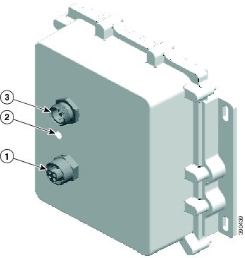
|
1 |
DC output connector |
3 |
DC input power connector |
|
2 |
Status LED |
 Feedback