Overview
The Cisco UCS 6536 Fabric Interconnect (UCSC-FI-6536) is a 1-rack unit (RU), top of rack (TOR), fixed-port data center platform that provides both network connectivity and management capabilities to the Cisco UCS system.
The fabric interconnect can provide Ethernet and Fibre Channel connectivity to the servers in the system. The servers connect to the fabric interconnect, and then to the LAN or SAN.
High availability redundancy can be achieved when a fabric interconnect is connected to another fabric interconnect through the L1 or L2 port on each device.
Each Cisco UCS 6536 Fabric Interconnect offers the following features:
-
Thirty-six QSFP28 ports capable of 100G including 4 unified ports (33-36). Ports also support:
-
Autonegotiating with peer devices to speeds of 40G, 25G, 10G, and 1G.
-
Port breakout is supported for Ethernet ports (1-32) and Unified ports (33-36).
-
Ethernet breakout is supported on chassis ports 1 through 36 when each port is configured with a breakout cable.
-
The Dynamic Ethernet Breakout feature enables converting a standard Ethernet port to a breakout port on-the-fly so that you do not need to reboot the Fabric Interconnect. Dynamic Ethernet Breakout also supports converting breakout ports back to a standard Ethernet port without a reboot.
-
-
FC breakout is supported on chassis ports 33 through 36 when each port is configured with a four-port breakout cable, for example 1/33/1, 1/33/2, 1/33/3, and 1/33/4 for four FC breakout ports on chassis physical port 33.

Note
Fibre Channel support is only available via configuring Unified Ports (33-36) as FC breakout.
-
FC breakout ports support peer communication at fixed speeds of 8Gbs, 16 Gbps, and 32 Gbps.
-
All four FC breakout ports must be configured with the same speed. Mixed speeds on a QSFP port's FC breakout ports are not supported.
-
Using breakout ports enables the fabric interconnect to support the maximum 16 FC ports supported by Fibre Channel.
-

Note
Converting from Ethernet to FC breakout ports, or FC breakout ports back to Ethernet, requires a reboot/reload after changing the breakout type.
For additional information about breakout capabilities, see Port Breakout.

Note
FCoE storage ports are not supported.
-
-
-
One management port (one 10/100/1000BASE-T port)
-
Two L1/L2 Ethernet RJ-45 ports for high availability or cluster configurations. Ethernet ports support 10/100/1000Mb speed.
-
One console port (RS-232)
-
One USB 3.0 port
-
CPU: 4 Core, 1.8GHz, Intel 5th-Generation core processor
-
Memory:
-
32 GB DDR4 DIMMs
-
128 GB M.2 SSD Flash Drive
-
32 GB Boot Flash (16 MB primary, and 16 MB standby/golden)
-
This fabric interconnect includes the following user-replaceable components:
-
Fan modules (6), each is a port-side exhaust fan module with dark grey latch coloring (UCS-FAN-6536).
-
Power supply modules (2). One power supply module (PSU) is the active module for operations, and the second PSU is the standby for redundancy [1+1]) with the following choices:
-
1100-W AC power supply with dark grey latch coloring (UCS-PSU-6536-AC)

Note
All fan modules and power supplies must use the same airflow direction.
-
The following figure shows the fabric interconnect features on the port side of the chassis.

|
1 |
LEDs |
3 |
36 40/100-Gigabit QSFP28 ports |
|
2 |
Lane Select button |
To determine which transceivers, adapters, and cables are support the fabric interconnect, see the Cisco Transceiver Modules Compatibility Information document.
The following figure shows the fabric interconnect features on the power supply side of the chassis.

|
1 |
Power supply modules (1 or 2) (AC power supplies shown) with slots numbered 1 (left) and 2 (right). For additional information, see Power Supply LEDs. |
2 |
Fan modules (6) with slots numbered from 1 (left) to 6 (right). For additional information, see Fan Module LEDs. |
|
3 |
Layer 2 (L2) Ethernet port, 10/100/100Mb autonegotiating. Supports high availability (HA) or clustering through an RJ-45 port. For additional information, see High Availability Port LEDs. |
4 |
Layer 1 (L1) Ethernet port, 10/100/100Mb autonegotiating. Supports high availability (HA) or clustering through an RJ-45 port. For additional information, see High Availability Port LEDs. |
|
5 |
Ethernet network management port (RJ45), 10/100/1000Mb autonegotiating For additional information, see Network Management and Console Port LEDs. |
6 |
Serial Console port (RJ45), 9600 baud. For additional information, see Network Management and Console Port LEDs. |
|
7 |
USB 3.0/2.0 port Supports booting the system and downloading scripts. |
8 |
Beacon (BCN) LED For additional information, see Fabric Interconnect Chassis LEDs. |
|
9 |
Status (STS) LED For additional information, see Fabric Interconnect Chassis LEDs. |
- |
The following figure shows the side of the chassis.

|
1 |
Screw holes for mounting brackets |
2 |
Grounding pad |
Plan to position the ports in a hot aisle so that fans and power supplies intake air from the cold aisle, blow the cool air through the fabric interconnect, and exhaust the heated air into the hot aisle.
The fan and power supply modules are field replaceable. You can replace one fan module or one power supply module during operations so long as the other modules are installed and operating. If you have only one power supply installed, you can install the replacement power supply in the open slot before removing the original power supply.
 Note |
All fan and power supply modules must have the same direction of airflow. Otherwise, the fabric interconnect can overheat and shut down. |
 Caution |
Because fans and power supply modules have port-side exhaust airflow (blue coloring for fan modules), you must locate the ports in the hot aisle. If you locate the air intake in a hot aisle, the fabric interconnect can overheat and shut down. |
Fabric Interconnect Chassis LEDs
The BCN, STS, and ENV, LEDs are located on the left side of the front of the fabric interconnect. The port LEDs appear as triangles pointing up or down to the nearest port.
|
LED |
Color |
Status |
|---|---|---|
|
BCN |
Flashing blue |
The operator has activated this LED to identify this fabric interconnect in the chassis. |
|
Off |
This fabric interconnect is not being identified. |
|
|
STS |
Green |
The fabric interconnect is operational. |
|
Flashing amber |
The fabric interconnect is booting up. |
|
|
Amber |
Temperature exceeds the minor alarm threshold. |
|
|
Red |
Temperature exceeds the major alarm threshold. |
|
|
Off |
The fabric interconnect is not receiving power. |
|
|
ENV |
Green |
Fans and power supply modules are operational. |
|
Amber |
At least one fan or power supply module is not operating. |
|
|
(port) |
Green |
Port admin state is 'Enabled', SFP is present, and the interface is connected (that is, cabled, and the link is up). |
|
Amber |
Port admin state is 'Disabled, or the SFP is absent, or both. |
|
|
Off |
Port admin state is 'Enabled' and SFP is present, but interface is not connected. |
Lane Link LEDs
The Lane Link LEDs indicate which of the breakout lanes are being checked. If none of the Lane Link LEDs is lit, all four lanes are being checked.
| LED Lit | Description |
|---|
Power Supply LEDs
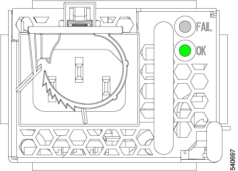
The power supply LEDs are located on the right upper corner of the power supply.

Combinations of states indicated by the OK and FAILLEDs indicate the status for the module as shown in the following table.
|
|
|
Status |
|---|---|---|
|
Green |
Off |
Power supply is on and outputting power to the fabric interconnect. |
|
Flashing green |
Off |
Power supply is connected to a power source but not outputting power to the fabric interconnect—power supply might not be installed in the chassis. |
|
Off |
Off |
Power supply is not receiving power. |
|
Green |
Flashing amber |
Power supply warning—possibly one of the following conditions:
|
Fan Module LEDs
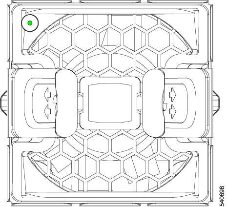
The fan module LED is located in the upper left corner above the air holes on the front of the module.

Each fan module has a Status LED that indicates the health of the fan module.
| LED | Color | Status |
|---|---|---|
|
STS |
Green |
The fan module is operational. |
|
Red |
The fan module is not operational (fan is probably not functional). |
|
|
Off |
Fan module is not receiving power. |
Management Port LEDs
The management port block consists of high availability fabric interconnect ports and serial console ports between fan 6 and PSU 2. LEDs for each port are at the top edges of each port.
See the following.
High Availability Port LEDs
The fabric interconnect has an L1 and L2 Ethernet port which can be used for high availability or clustering. Each port has a pair of LEDs, one indicates link and the other indicates activity.
|
LED Location |
LED State |
Indicates |
|---|---|---|
|
Left |
Off |
No physical link |
|
Left |
Solid Green |
Physical link detected |
|
Right |
Off |
No Activity |
|
Right |
Blinking Green |
Activity |
Network Management and Console Port LEDs
The fabric interconnect has an RJ45 network management port and an RJ45 console port between fan 6 and PSU 2. Each port has a pair of LEDs, one indicates link and the other indicates activity.
|
LED Location |
LED State |
Indicates |
|---|---|---|
|
Left |
Off |
No physical link |
|
Left |
Solid Green |
Physical link detected |
|
Right |
Off |
No Activity |
|
Right |
Blinking Green |
Activity |
 Feedback