Managing External Resources
Revised: August 10, 2011, OL-25015-01
Introduction
This chapter tells you how to manage external resources provisioned on the BTS using administrative (ADM) commands. External resources have two service states:
• Administrative—State the BTS user provisions for the resource link
•Operational—Physical condition of the resource link or the resource)
The two types of service states are independent of each other, for example:
A user places an MGW link in-service; its administrative state is ADMIN_INS. But that link between the BTS and MGW is lost. The MGW link's operational state is MGW_STATUS_DOWN.
A query of the MGW returns both the administrative state and operational state.
Viewing BTS System-Wide Status
BTSSTAT runs on any BTS host. Any valid UNIX user can enter btsstat from a UNIX shell to initiate it. This command returns the following for all BTS components:
•Component id
•Side
•Host name
•Version
•Replication status
•Redundancy status
To run BTSSTAT from a non-BTS host, the configuration file needs the information in following table. BTSSTAT ignores all other lines in the file.
Table 5-1 Using BTSSTAT
|
|
|
Viewing status of entire BTS system (including components not on the same host) |
|
Viewing status of specific components |
CA
FSAIN
FSPTC
EMS
BDMS
|
Running BTSSTAT from a non-BTS host (requires an SSL connection to the BTS) |
Specify BTS hosts in a configuration file: •CA_SIDE_A_HN = prica11
CA_SIDE_B_HN = secca11 •FSAIN_SIDE_A_HN = prica11
FSAIN_SIDE_B_HN = secca11 •FSPTC_SIDE_A_HN = prica11
FSPTC_SIDE_B_HN = secca11 •EMS_SIDE_A_HN = priems11
EMS_SIDE_B_HN = secems11 •BDMS_SIDE_A_HN = priems11
BDMS_SIDE_B_HN = secems11 |
Viewing BTS software version and installed patches |
|
Managing Trunk Groups and Trunks
Table 5-2 Managing Trunk Groups
|
|
|
Viewing TG status |
Possible operational states: •in-service •out of service •manually busy •operate in wait state, operate in standby state •restore session request normal, restore session request switchover, restore session request maintenance, restore session fail normal, restore session fail switch-over, restore session fail maintenance, restore establish request normal, restore establish request switchover, restore establish request maintenance, restore establish fail normal, restore establish fail switchover, restore establish fail maintenance •in maintenance state •down session set fail soft normal, down session set fail hard normal, down session set fail soft maintenance, down session set fail hard maintenance, down establish request soft normal, down establish request hard normal, down establish request soft maintenance, down establish request hard maintenance, down establish request hard normal, down establish request soft maintenance, down establish request hard maintenance, down establish fail soft normal, down establish fail hard normal, down establish fail soft maintenance, down establish fail hard maintenance •delete graceful •request remove release, request remove session set •remove graceful in-service and maintenance state •DPC is inaccessible |
Viewing TGs with ISDN D channels |
|
Switching ISDN D channels |
control isdn-dchan tgn-id=1;
This switches the active D channel to standby, and the standby D
channel to active.
|
Changing TGs states |
control trunk-grp tgn-id=129; mode=forced; target-state=oos;
Note Before bringing an ISDN trunk in-service, put the connected media gateway in-service, see Changing media gateways status. |
Viewing trunk status |
status trunk-termination tgn-id=2; cic=8;
|
Resetting trunks |
reset trunk-termination tgn-id=13; cic=1-6;
Resetting does the following: •Clears all manual and blocked states •Clears active/transient calls on a trunk termination, with the exception of SS7 trunk terminations. •Brings trunks INS |
Changing trunk states |
control trunk-termination tgn-id=17; cic=1-23;
target-state=ins; mode=forced;
equip trunk-termination tgn-id=13; cic=all;
Changes trunks in UEQP to OOS
unequip subscriber-termination id=97_8@ipclab.cisco.com;
Changes OOS trunks to UEQP |
Forcing MAINT state |
SS7 trunks control ss7-trunk-termination tgn-id=103; mode=forced; target-state=maint; Note Set COT on the terminating gateway or switch to perform these tests. Otherwise, the test or tests fail. ISDN trunks control isdn-trunk-termination tgn-id=17; mode=forced; target-state=maint; CAS trunks control cas-trunk-termination tgn-id=64; mode=forced; target-state=maint; Announcement trunks control annc-trunk-termination tgn-id=13; mode=forced; target-state=maint; |
Viewing test menus |
SS7 trunks diag ss7-trunk-termination test=<TAB> diag ss7-trunk-termination test=<RETURN> ISDN trunks diag isdn-trunk-termination test=<TAB> diag isdn-trunk-termination test=<RETURN> CAS trunks diag cas-trunk-termination test=<TAB> diag cas-trunk-termination test=<RETURN> Announcement trunks diag annc-trunk-termination test=<TAB> diag annc-trunk-termination test=<RETURN> |
Testing trunks (place in MAINT state first) |
SS7 trunks
diag ss7-trunk-termination tgn-id=103; cic=13; test=1;
Test 1: SS7 MGCP Connectivity Test—tests if MGCP has access to the SS7 trunk termination Test 2: SS7 Termination Connection Test—tests if there is a path to the device (ping). Test 3: SS7 COT Test—tests the integrity of the SS7 Bearer Path. Test 4: SS7 CQM Test—queries the SS7 circuit (or group of circuits) status. A range of CICs can be specified (to a maximum of 24). Both remote and local trunk states are displayed in the results. Test 5: SS7 CVT Test—tests to ensure that each end of the circuit has sufficient and consistent information for using the circuit in call connections. CLLI names are included. Test 6: SS7 CIC Audit—returns status of CICs Test 0: ALL—performs tests 1 through 6. ISDN trunks
diag isdn-trunk-termination test=1; tgn-id=17; cic=1;
1. Tests if MGCP has access to the ISDN termination 2. Tests if there is a path to the device (ping) 3. Performs tests 1 and 2 CAS trunks
diag cas-trunk-termination tgn-id=64;cic=1;test=1;
1. Tests if MGCP has access to the CAS termination 2. Tests if there is a path to the device (ping) 3. Performs tests 1 and 2 Announcement trunks
diag annc-trunk-termination;test=1;tgn-id=13;cic=1
1. Tests if MGCP has access to the ANC termination 2. Tests if there is a path to the device (ping) 3. Performs tests 1 and 2 |
Table 5-3 Valid Normal Trunk Termination States
|
|
|
|
|
|
UNEQP |
UNEQP |
ANY |
UEQP |
IDLE |
MANUALLY OOS |
OOS |
ANY |
LBLK |
IDLE |
MANUALLY MAIN |
MAINT |
IDLE |
LBLK |
IDLE |
IDLE |
INS |
IDLE |
ACTV |
IDLE |
ACTIVE INCOMING |
INS |
IDLE |
ACTV |
IDLE |
ACTIVE OUTGOING |
INS |
ACTIVE |
ACTV |
OBSY |
TRANSIENT INCOMING |
INS |
ACTIVE |
ACTV |
IBY-TRNS |
TRANSIENT OUTGOING |
INS |
BUSY |
ACTV |
OBSY-TRNS |
If a TG or trunk command fails, it can return one of the following generic failure reasons, as well as ones specific to the command.
Table 5-4 Understanding Trunk Group and Trunk Generic Command Responses
|
|
|
|
|
or
|
Failure |
TG or trunk database was not found in shared memory. Component is already in the requested state. Graceful mode only. Appears when a command is executed and operation is INS going OSS or INS going MAINT. A required resource is not available. For ISDN –A trunk cannot be added unless both the MGW and TG are available. –A TG cannot be added unless the MGW is available, and vice versa. For SS7, CAS, Announcement –A trunk cannot be added unless both the MGW and TG are available. –A TG does not require the MGW to be available, and vice versa. An associated resource of the database cannot be found. An assigned resource is not valid (supported). |
|
|
|
|
|
any |
Failure |
• Found no failure •TG(s) cannot be found, trunk(s) cannot be found, no TG(s) found in trunking gateway, no trunk(s) found in TG •Fail while in termination table, fail while in TG table, fail while in trunk table, fail while looking to find trunk index, fail while getting TG administration state •Failed to allocate IPC message(s), failed to dispatch IPC message(s) •Operational state invalid, administration state invalid •Trunk(s) state change and pending •Found TG type invalid, found TG state invalid, found TG admin state not ready •Entity in desired state •Not allow trunk to reset •Change to out-of-service state required, change to request graceful mode error •Found entity unequipped in initial state •Operation not allowed because D Channel(s) is down •Found unknown failure reason(s) |
Trunk Termination commands |
Failure |
•The transaction could not be executed due to a transient error, the endpoint is unknown, the endpoint is not ready, endpoint does not have enough resources available, a protocol error was detected, the command contained an unrecognized extension, the endpoint is restarting. •Invalid conn identifier, invalid call ID. •Unsupported mode or invalid mode, unsupported or unknown package. •Endpoint does not have a digit map, endpoint redirected to another Call Agent, endpoint malfunctioning, endpoint taken out of service. •No such event or signal. •Unknown action or illegal combination of actions. •Internal consistency in local connection options, unknown extensions in local connection options, unsupported values on local connection options. •Insufficient bandwidth. •Missing remote connection descriptor. •Incompatible protocol version. •Internal hardware failure. •CAS signaling protocol error. •Failure of a group of trunks. •Response too big. •Loss of lower connectivity. •No fault reason available. |
Trunk commands |
Failure |
•NON-FAULTY—Not blocked, available for service. •MAINT-OOS—Trunk-termination is manually controlled OOS. •MAINT-BUSY—Trunk-termination is in maintenance state; controlled to MAINT. •TERM-FAULT—Bearer termination is in faulty condition. •SIGNALLING-FAULT—Signaling link (for example, SS7 link, or ISDN D channel) is faulty. •MAINT-BLOCK—Trunk-termination is manually controlled OOS (controlled mode=GRACE). •HARDWARE-BLOCK—Trunk-termination is manually controlled OOS (controlled mode=FORCED). •OUTGOING_RESTRICTED—The outgoing call is not allowed •DPC_INACCESSIBLE—The DPC is not accessible. •ACL_CONGESTION_LEVEL_1—Automatic Congestion Level (ACL) congestion is at level 1. •ACL_CONGESTION_LEVEL_2—ACL congestion is at level 2. •ACL_CONGESTION_LEVEL_3—ACL congestion is at level 2. •TFC_CONGESTION_LEVEL_1—Transfer Controlled (TFC) congestion is at level 1. •TFC_CONGESTION_LEVEL_2—TFC congestion is at level 2. •TFC_CONGESTION_LEVEL_3—TFC congestion is at level 3. |
SS7 trunk commands |
Failure |
•ACT_LOC_INIT_RESET—Reset circuit at startup. •ACT_LOC_MML_RESET—Craft reset request. •ACT_LOC_QUERY—Circuit query. •ACT_LOC_UPU—Action to perform user part unavailable. •ACT_LOC_VALIDATE—Circuit validation. •ACT_LOC_COTTEST—COT test. •ACT_LOC_STOP—Action to stop the call. •BLK_LOC_UPU—Trunk is blocked because user part is unavailable. •DES_LOC_GRACE—Local hardware RSIP graceful. •DES_LOC_SIG—SS7 signaling fault (link fail). •DES_LOC_FORCE—Local hardware RSIP forced. •DES_LOC_MML—MML; also used for unsolicited blocks from MDL due to circuit query reservation (CQR). •DES_LOC_UPU—Trunk needs to be blocked because of user part unavailability. •JOB_PENDING—Ongoing job in progress. •JOB_REC—Job was received by the MDL component and is being processed. •OPER_ACTIVE—Trunk is available for calls. •REMOTE_GRACE—Trunk is blocked remotely because of a CLI command on the remote switch. •REMOTE_FORCE—Trunk is blocked remotely because of a hardware failure on the remote switch. •RESERVE_SPARE1—Reserved for future use. •RESERVE_SPARE2—Reserved for future use. •TERM_GRACE—Trunk is gracefully blocked because of an RSIP graceful from the MGW. |
Managing Subscriber Terminations
Table 5-5 Managing Subscriber Terminations
|
|
|
Checking subscriber status |
status subscriber-termination id=ubr204_1;
Possible states: •ADMIN-UEQP—Unequipped. –Newly-provisioned subscriber terminations are UEQP –Place a subscriber termination in UEQP before deleting it •ADMIN-INS—In-service •ADMIN-OOS—Out of service •ADMIN-MAINT—Maintenance Mode •ADMIN-OOS-PENDING—Transitioning to out of service •ADMIN-MAINT-PENDING—Transitioning to Maintenance Mode |
Checking subscriber status in detail |
status subscriber-termination id=*@ubr235; oper-state=FA;ISDN
Administrative and Operational Maintenance States for a Trunking
Gateway
For more information use one of the following for oper-state: •FA—Faulty •NF—Not faulty •IDLE—Termination idle •ACTIVE—Termination active •DOWN—Termination down •TERM-FA—Termination fault •TEMP-DOWN—Termination temporarily down •UNREACH—Termination unreachable •INT-MAINT—Termination internal maintenance •UEQP—Termination unequipped •ALL—All states, same as executing command without oper-state token |
Changing subscriber termination states |
control subscriber-termination id=*@c3810_167; mode=forced; target-state=INS;
Possible states: •INS—In-service •OOS—Out of service •MNT—Maintenance mode control subscriber-termination id=sub2-ctx2; mode=forced; target-state=maint; Forces MAINT state, do this before testing
equip subscriber-termination id=97_8@ipclab.cisco.com;
Changes OOS subscriber terminations to UEQP
unequip subscriber-termination id=97_8@ipclab.cisco.com;
Changes INS subscriber terminations and puts them in UEQP, subscriber terminations state must be UEQP before you can delete them. |
Viewing test menus |
diag subscriber-termination; test=<TAB> diag subscriber-termination; test=<RETURN> |
Testing subscriber terminations (place subscriber terminations in MAINT state first) |
diag subscriber-termination id=sub-ubr3-1@cisco.com; test=3;
ring-duration=10;
Note Ring-duration values are 0-999 (Default = 5). Maximum ring time is 30 seconds regardless of whether the duration is set higher than or equal to 31. 1. Tests if MGCP has access to the termination 2. Tests if there is a path to the device (ping) 3. Tests if the subscriber can be rung 4. Performs tests 1 through 3 |
If a subscriber termination command fails, it can return one of the following generic failure reasons, as well as ones specific to the command.
Table 5-6 Understanding Subscriber Command Responses
|
|
|
|
|
or
|
Failure |
•Subscriber database was not found in shared memory. •Component is already in the requested state. •Graceful mode only, this appears when a command is executed and operation is INS going OSS or INS going MAINT. •A required resource is not available. For example: The MGW for a subscriber is down, the subscriber cannot be added. •An associated resource of the database cannot be found. •An assigned resource is not valid (supported). For example, a subscriber is assigned to a PBX and the PBX is not supported. |
|
|
|
|
|
Any |
failure |
•Found no failure, subscriber category invalid, entity unequipped in initial state, unknown failure reason(s). •Subscriber(s) cannot be found, subscriber(s) state change and pending. •No termination(s) found in MGW. •Fail while in termination table. •Administration state invalid, operational state invalid. •Failed to allocate IPC message(s), failed to dispatch IPC message(s). •Entity in desired state. •Not allow subscriber to reset. •Change to out-of-service state required. |
Subscriber commands |
Failure |
•The media gateway is down, unreachable, in a faulty state, transitioning to another state. •The transaction could not be executed because the endpoint is unknown, the endpoint is not ready, the endpoint does not have enough resources available, the endpoint is restarting, the command contained an unrecognized extension, the gateway is not equipped to detect one of the requested events, the gateway is not equipped to generate one of the requested signals, the gateway cannot send the specified announcement. •Invalid conn identifier, invalid call ID. •Unsupported mode or invalid mode, unsupported or unknown package. •Endpoint does not have a digit map, endpoint redirected to another Call Agent, endpoint malfunctioning, endpoint taken out of service. •No such event or signal. •Unknown action or illegal combination of actions. •Internal consistency in local connection options, unknown extensions in local connection options, unsupported values on local connection options. •Insufficient bandwidth. •Missing remote connection descriptor. •Incompatible protocol version. •Response too big. •Loss of lower connectivity. •No fault reason available. |
Managing Gateways
Table 5-7 Managing Gateways
|
|
|
Viewing H.323 gateways |
status h323-gw id=CHINA-1;
Possible RAS states: •CCH323_RAS_STATE_NONE—operational state is ADMIN OOS •CCH323_RAS_STATE_GRQ—Gatekeeper Discovery state •CCH323_RAS_STATE_RRQ—Gateway Registration state •CCH323_RAS_STATE_IDLE—ready for calls •CCH323_RAS_STATE_URQ—Un-registration state. |
Setting the state of H.323 gateways |
control h323-gw id=CHINA_1; target-state=INS;
|
Viewing signaling gateway processes (SGPs) |
|
Viewing media gateways status |
Possible states: •ADMIN-INS—In-service •ADMIN-OOS—Out of service •ADMIN-MAINT—Maintenance Mode •ADMIN-OOS-PENDING—Transitioning to out of service •ADMIN-MAINT-PENDING—Transitioning to Maintenance Mode |
Reporting all MTAs that use "best effort" (non DQoS) calls in the network having or not having a specific aggr id |
report mgw id=%; oper-status=qos-best-effort; aggr-id=aggr1;
start_row=1; limit=5;
Displays the output as CLI as the output-type has not been mentioned
report mgw id=%; oper-status=qos-best-effort; aggr-id=%;
output-type=xml; start_row=1; limit=5; output=report;
Displays the output in the specific format (CSV/XML) based on the output-tpye specified
Note The output displays only those mgws that use NCS variant. |
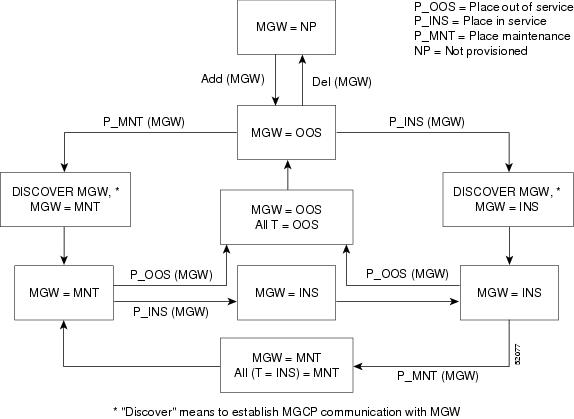
Changing media gateways status |
control mgw id=c5300_162; mode=forced; target-state=INS;
Modes can be forced or graceful. Forced tears down all calls immediately; graceful allows calls in progress to complete before teardown. Note Rules for changing an MGW states are in Figure 5-1. control mgw id=c2421.65; mode=forced; target-state=maint; Forces MAINT state, do this before testing |
Viewing media gateway test menus |
or

diag mgw test= <RETURN>
|
Testing media gateways (place gateways in MAINT state first) |
diag mgw id=ubr-03; test=1;
|
If a gateway command fails, you might receive one of the following generic failure reasons, or one specific to the command.
Table 5-8 Understanding Gateway Command Responses
|
|
|
|
status or
|
Failure |
•Media gateway database was not found in shared memory. •Component is already in the requested state. •Graceful mode only. Appears when a command is executed and operation is INS going OSS or INS going MAINT. •A required resource is not available. •An associated resource of the database cannot be found. •An assigned resource is not valid (supported). |
|
|
|
|
|
any |
Failure |
•Found no failure. •MGW(s) cannot be found, no termination(s) found in MGW, MGW(s) state change and pending, found MGW admin state not ready. •No TG(s) found in trunking gateway. •Fail while getting MGW administration state, fail while looking for MGW index. •Administration state invalid. •Failed to allocate IPC message(s), failed to dispatch IPC message(s). •Operational state invalid. •Subscriber(s) state change and pending. •Trunk(s) state change and pending. •Found subscriber category invalid. •Entity in desired state. •Change to out-of-service state required. •Change to request graceful mode error. •Found entity unequipped in initial state. •The H.323 Gateway was not found in DBM. •Found unknown failure reason(s). |
Managing Other External Resources
Table 5-9 Managing External Resources
|
|
|
Viewing SIP phones |
status sip-reg-contact
aor-id=4695551885@SYS44CA146.boston3.com;
|
Viewing aggregation router status |
|
Shows all CMTS (Aggr-ID) that are not referred by any Subnet. |
|
Viewing destination point codes (DPCs) status for availability and congestion |
|
Viewing Stream Control Transmission Protocol (SCTP) associations |
status sctp-assoc id=sctpassoc1;
|
Taking an SCTP association OOS |
control sctp-assoc id=sctpassoc1; target-state=INS;
mode=FORCED;
Modes can be forced or graceful. Forced tears down all calls immediately; graceful allows calls in progress to complete before teardown. |
Viewing subsystems |
|
Viewing subsystems status |
status subsystem id=LNP_SSN; opc_id=opc;
|
Changing subsystem status |
control subsystem id=LNP_SSN; opc_id=opc; target-state=OOS;
mode=FORCED;
|
Viewing CA/FS status |
|
Changing CA/FS status refresh rate |
change sup-config type= refresh-rate; value=600
|
Changing NTP servers |
1. Modify 'server' line(s) in /etc/ntp.conf. 2. Modify 'NTP_SERVERS' in /etc/opticall.cfg 3. Restart daemon: /etc/init.d/xntp stop /etc/init.d/xntp start 4. Verify configuration change: /opt/BTSxntp/bin/ntpq -c peers" |
Ensuring billing server receives Call Detail Blocks (CDBs) |
1. On both the primary and secondary EMS enter:
CLI>show billing-acct-addr
2. Note the polling interval. 3. Log in to the billing server. 4. Ensure it receives billing files every XX minutes from the BTS, where XX = polling interval. |
Clearing billing directory |
 |
Caution Remove only transferred or secondary files. Never remove primary files, you need these to collect revenue.
|
1. Check the default format secondary files:
<billing-file-prefix>-<call-agent-id>-(0/1){+/-}HHMMSS-yyyymmdd-hhmmss-<sequence-number>-<S>
where S=secondary state 2. Check the PacketCable-specific format secondary files:
<billing-file-prefix>_yyyymmddhhmmss_<priority>_<1>_<cms-id>_<sequence-number>.ascii[.tmp]
where 1=secondary record-type 3. On the secondary EMS enter <hostname>#df -k 4. Ensure the /opt directory is not more than 70% full.
If the /opt directory is >70% full, remove obsolete scripting files and other user-generated files. Also remove obsolete files from the backup directory. For help call Cisco TAC. |
Learning External Resource Dependencies
Table 5-10 RGW and Subscriber Termination States
|
|
Allowed Subscriber Termination States
|
OOS |
•OOS •UEQP |
INS |
•OOS •MAINT •INS •UEQP |
MAINT |
•OOS •MAINT •UEQP |
Table 5-11 ISDN TGW/TG State Relationships
|
|
|
INS |
•OOS •MAINT •INS |
MAINT |
•OOS •MAINT |
This table lists the administrative states BTS returns.
Table 5-12 Returnable Administrative States
|
|
|
ADMIN-INS |
In service. |
ADMIN-OOS |
Out of service. |
ADMIN-MAINT |
Maintenance Mode. |
ADMIN-OOS-Pending |
Transitioning to out of service. |
ADMIN-MAINT-Pending |
Transitioning to Maintenance Mode. |
ACL |
Congestion is at level 1 |
ACL |
Congestion is at level 2 |
ACL |
Congestion is at level 3 |
TFC |
Congestion is at level 1 |
TFC |
Congestion is at level 2 |
TFC |
Congestion is at level 3 |
Table 5-13 ISDN TGW/TG State Relationships
|
|
|
|
INS |
•OOS •MAINT •INS |
•UEQP OOS •UEQP OSS, MAINT •UEQP OOS, MAINT, INS |
MAINT |
•OOS •MAINT |
•UEQP OOS •UEQP OSS, MAINT |
Table 5-14 Valid Normal Trunk Termination States
|
|
|
|
|
|
UNEQP |
UNEQP |
ANY |
UEQP |
IDLE |
MANUALLY OOS |
OOS |
ANY |
LBLK |
IDLE |
MANUALLY MAIN |
MAINT |
IDLE |
LBLK |
IDLE |
IDLE |
INS |
IDLE |
ACTV |
IDLE |
ACTIVE INCOMING |
INS |
IDLE |
ACTV |
IDLE |
ACTIVE OUTGOING |
INS |
ACTIVE |
ACTV |
OBSY |
TRANSIENT INCOMING |
INS |
ACTIVE |
ACTV |
IBY-TRNS |
TRANSIENT OUTGOING |
INS |
BUSY |
ACTV |
OBSY-TRNS |
 |
Note If a call termination attempt is made on a termination for which gateway is unreachable, the termination status will be updated as unreachable even if MGW keepalive is disabled.
|
Table 5-15 Returnable Operational States
|
|
|
UNKNOWN |
•The termination is not being audited for connectivity. •Capabilities, termination, and connection are not being synchronized with the termination. •When KEEPALIVE-METHOD=NONE in MGW-PROFILE, the termination status is UNKNOWN even if the transaction becomes UNREACHABLE. •Newly-provisioned terminations are in this state. |
ACTIVE |
•The termination is being audited for connectivity. •Capabilities, termination, and connection are being synchronized with the termination. |
UNREACHABLE |
•The termination is unreachable. •This occurs when MGW KEEPALIVE declares an MGW unreachable. •This changes to ACTIVE when MGW KEEPALIVE detects an MGW is reachable or any termination previously UNREACHABLE starts sending MGCP messages (NTFY, RSIP). |
FAULTY |
•The termination returneda permanent error code, making it unusable for future calls.
|
Note The error code may occur only in certain circumstances and re-audit/auto-recovery may succeed. This does not mean the termination recovered from that condition.
|
•The flag MGCP-MAX-FAULT-COUNT controls how many times BTS tries to recover the fault (performing re-audit/auto-recovery) before putting it in this state. |
MTRANS |
•Maintenance Transient, the termination is in the middle of anaudit/re-audit/auto-recovery. •This state may go along with other states (MTRANS-UNREACH). |
IDLE |
The termination is not involved in transient/active call |
BUSY |
•The termination is involved in Active/Transient call. •This state may go along with CTRANS state. |
CTRANS |
•Call Transient, the termination is involved in a Transient call. •This state always goes with BUSY. |
RESERVED |
The termination is reserved for a call during Busy Line Verification |
SERV_EFFC_TEST |
The termination is in a Service Effecting Network loopback or Network Continuity test. |
DOWN |
This occurs when the MGW sends an RSIP down (graceful) message. |
Source Token
Figure 5-1 Administrative and Operational Maintenance States for MGW
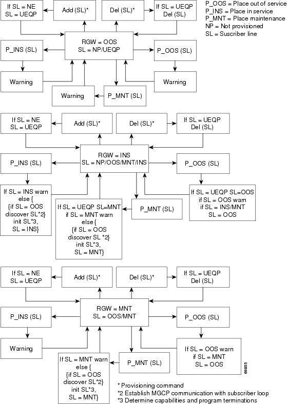
Figure 5-2 Administrative and Operational Maintenance States for Residential Gateways
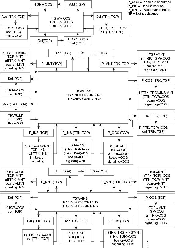
Figure 5-3 ISDN Administrative and Operational Maintenance States for a Trunking Gateway
GigE Support
The purpose of implementing the GigE Support Feature provisioning is to increase the bandwidth between the network switches and the Cisco BTS 10200 from 100 Mbps to 1000 Mbps.
This section describes the steps needed to enable GigE support on the UNIX hosts of the Cisco BTS 10200 Softswitch. Use this procedure only after you upgrade to Cisco BTS 10200 Release 6.0(1) or later.
|
Caution This is not an upgrade procedure. Performing the steps in this procedure will bring the Cisco BTS 10200 down on one side with temporary loss of redundancy. Do not start this procedure unless you have authorization from your supervisor. If you have questions, contact Cisco Technical Assistance Center (TAC).
|
|
Caution Perform this procedure on one UNIX host at a time.
|
|
Caution This procedure should be executed by a person very familiar with the operation and administration of the Cisco BTS 10200 and 29xx switches as well as the network and cabling of the Cisco BTS 10200.
|
Prerequisites
1. The Cisco BTS 10200 Softswitch Release 6.0(1) must already be installed.
2. The BTS 10200 UNIX host must have network interfaces capable of running at GigE speed (1000 Mbps).
Provisioning the GigE Interface
For each host in Cisco BTS 10200, perform the following steps:
Step 1 Ensure that the targeted Cisco BTS 10200 applications are operating in standby mode. These applications include the Call Agent (CA), the Feature Server for POTS, Tandem, and Centrex services (FSPTC), the Feature Server for AIN services (FSAIN), the Element Management System (EMS), and the Bulk Data Management System (BDMS). If necessary, perform a switchover to ensure this is the case.
Step 2 Use the platform stop all command to stop the targeted Cisco BTS 10200 applications running on the UNIX host.
Step 3 Identify and note the Ethernet ports on the 29xx switches that connect to the Cisco BTS 10200 UNIX host.
Step 4 Modify the configuration of the switch ports connected to the Cisco BTS 10200 UNIX host to auto negotiate. To do so, first log in to the 29xx switch through console access, change to the switch port, and modify the speed and duplex mode settings on each port using the following commands:
Step 5 Save the switch configuration.
Step 6 Reboot the Cisco BTS 10200 host using the shutdown -g0 -y -i6 command. We recommend that you execute the shutdown command using the console port to avoid loss of connectivity during the reboot. After the reboot, all the targeted Cisco BTS 10200 applications should automatically restart and go into standby state.
Step 7 Verify interface speed and duplex mode by executing the following command on the host:
Example output:
bge0 link: up speed: 1000 Mbps duplex: full
bge1 link: up speed: 1000 Mbps duplex: full
bge2 link: up speed: 1000 Mbps duplex: full
bge3 link: up speed: 1000 Mbps duplex: full
Step 8 Repeat for the other UNIX hosts in the Cisco BTS 10200 system.
 Feedback