Cisco Unified Communications Gateway Services API Guide
Bias-Free Language
The documentation set for this product strives to use bias-free language. For the purposes of this documentation set, bias-free is defined as language that does not imply discrimination based on age, disability, gender, racial identity, ethnic identity, sexual orientation, socioeconomic status, and intersectionality. Exceptions may be present in the documentation due to language that is hardcoded in the user interfaces of the product software, language used based on RFP documentation, or language that is used by a referenced third-party product. Learn more about how Cisco is using Inclusive Language.
- Updated:
- November 4, 2011
Chapter: Overview of Cisco Unified Communication Gateway Services API
Cisco Unified Communications Gateway Services API
This chapter describes the Cisco Unified Communications Gateway Services Application Programming Interface (CUCGSAPI). The CUCGSAPI enables the development of advanced Cisco Unified Communication applications and services on the platforms running Cisco IOS and Cisco IOS XE software by providing an interface to the Cisco Unified Communications Gateway Services.
CUCGSAPI provides the developer with access to the following unified communications gateway services:
Feature Information for Cisco Unified Communications Gateway Services
Overview
CUCGSAPI allows you to develop an application that interacts with the Cisco Unified Communications Gateway Services on voice gateways. The application accesses the Cisco Unified Communications Gateway Services via SOAP messages.
You can configure secure and nonsecure modes of connectivity between Cisco Unified Communications Gateway Services and application. Nonsecure mode uses HTTP protocol and secure mode uses HTTPS protocol.
Figure 1-1 illustrates the Cisco Unified Communications Gateway Services interface in nonsecure mode. In nonsecure mode, Cisco supports the extended call control (XCC) provider, extended call detail record (XCDR) provider, extended serviceability (XSVC) provider, and extended media forking (XMF).
Figure 1-1 Cisco Unified Communications Gateway Services Interface in nonsecure mode
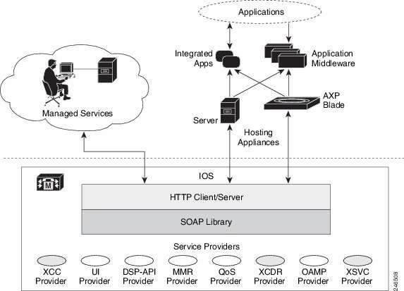
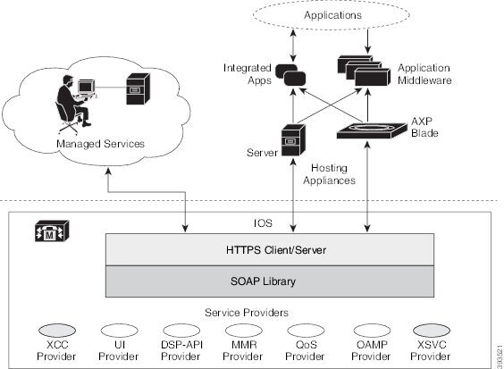
Figure 1-2 illustrates the Cisco Unified Communications Gateway Services interface in secure mode. In secure mode, Cisco supports the extended call control (XCC) provider, and extended serviceability (XSVC) provider.
Figure 1-2 Cisco Unified Communications Gateway Services Interface in secure mode
Cisco Unified Communications Gateway Services
Web service is a standards-based framework that allow applications operating on different platforms to interact over the Internet. Cisco Unified Communications Gateway Services, like web services, are platform independent and language neutral. With CUCGSAPI, you can develop your application in the language and operating system of your choice and communicate directly with the Cisco Unified Communications Gateway Services running on the voice gateway.
The Cisco Unified Communications Gateway Services API supports the following standards and protocol:
Behavioral Differences Between Nonsecure Mode and Secure Mode
Table 1-1 lists the differences in behavior between nonsecure and secure mode.
|
|
|
|
|---|---|---|
Cisco IOS software based platforms and Cisco IOS XE software based platforms |
||
Limitations
Providers
The providers on the voice gateway provide services on the voice gateway for remote applications. Cisco Unified Communications Gateway Services API enables applications to interact with the providers and is comprised of the following provider objects:
- XCC Provider— Extended Call Control (XCC) provider supports operations that allow an application to perform call control and real-time call monitoring.
- XCDR Provider—Extended Call Detail Record (XCDR) provider supplies CDR information to the application and notifies the application when calls have ended.
- XSVC Provider—Extended Serviceability (XSVC) provider monitors trunk status, and provides real-time link status and configuration change notification to application.
- XMF Provider—Extended Media Forking (XMF) provider monitors calls and trigger media forking on the calls and has the capability to service up to 32 applications.
Each provider has a unique URL identifier and communicates with the application via SOAP messages. The providers can be in one of two states:
- In-service—Provider is active and available for use.
- Shutdown—Provider is disabled and no longer available. The API methods associated with this provider are invalid in this state.
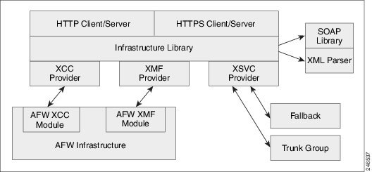
Figure 1-3 illustrates the relationship between the IOS components.
Figure 1-3 Cisco Unified Communications Gateway Services Components
When a provider is configured and enabled on the voice gateway, it performs the following functions:
- Manages the registration process between the application and the provider.
- Sends notification to the application when a provider changes its status.
- Passes incoming messages to the appropriate provider.
- Notifies the provider when there is a message exchange failure.
- Sends probing messages to maintain an active registration session.
- Sends negative probing messages to detect the status of an application. If the number of failed responses exceeds a configured number of negative probing messages, the voice gateway unregisters the application.
WSDL Files
CUCGSAPI uses the WSDL specification to define the services that are available on the voice gateway. These services are represented as providers on the voice gateway.
Table 1-2 lists the namespace for the Cisco Unified Communications Gateway Services
|
|
|
|---|---|
Inbound Ports
Table 1-3 lists the URL and inbound location that the application uses to communicate with the server in nonsecure mode.
|
|
|
|---|---|
http://<access_router>:8090/cisco_xcc 1 |
|
|
1.The access_router is the hostname or IP address of the router that with Cisco Unified Communications Gateway Services. Table 1-4 lists the URL and inbound location that applications uses to communicate with the server in secure mode. |
|
|
|
|---|---|
Registering an Application
Before an application can register with the voice gateway, you must first configure the application’s service URL on the voice gateway. The URL is used to authenticate messages from the application. When the voice gateway first boots up, the provider sends status messages to the applications that are in its configuration. The voice gateway sends status messages when the provider changes its status.
The application initiates registration by sending a registration message to the appropriate provider. The provider generates a unique registration ID and sends it back to the application. The unique registration ID identifies the registered session and is used in all messages that are sent during the registered session.
States of a Registered Session
The state of the registered session and the status of the messages that are sent between the provider and application have one of the following value:
- Steady State—This state is the normal state of the registered session. Messages and acknowledgements are exchanged regularly in this state.
- Keepalive State—When the provider does not have messages to send, the voice gateway sends keepalive probing messages to the registered application This keeps the connection between the application and the provider active. The messages that are sent in this state contain information on the health and connectivity status of the provider.
- Negative Probe State—When the number of failed responses exceeds the maximum number of failed responses, the registered session enters the negative probe state. In the negative probe state, the voice gateway sends negative-probing messages in an attempt to reestablish the steady state or the keepalive state with the application. The only message sent in a negative probe state is a negative probe message. The registered session returns to a steady state or keepalive state upon receipt of a successful response to a negative probe message, and regular messages resume.
- Unregistered State—The session is unregistered and no messages are exchanged between the provider and the application. The session enters an unregistered state under the following conditions:
–![]() When the application unregisters with the provider.
When the application unregisters with the provider.
–![]() When an application fails to respond to probing messages.
When an application fails to respond to probing messages.
–![]() When the administrator shuts down the provider service on the voice gateway.
When the administrator shuts down the provider service on the voice gateway.
XCC Provider
The XCC provider gives an application the capability to control all the legs of a standard call. With the XCC provider, the application can perform auxiliary call control and can control some network elements.
Characteristics of the XCC Provider
The XCC provider has the following characteristics:
- The XCC provider allows the application to maintain stateful control on a call over the entire life cycle of the call.
- The XCC provider allows the application to subscribe and receive mid-call event notification. The application can change event subscription over the life of the call.
- The XCC provider allows services to be invoked on a network triggered event. The provider reports on notifications from a direct application request.
- The XCC provider follows a generic call model in which the underlying communication protocol and architecture is hidden from the developer. XCC provider uses a high-level call control model for maintaining and managing the state of a call session.
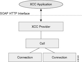
Figure 1-4 illustrates the XCC call control abstraction.
XCC Provider API
When an application registers with the XCC provider, the application configures event filter parameters that the application is interested in monitoring, and the XCC provider installs a connection listener to monitor the calls. XCC notifies the application when a call or connection event matches the event filters that were configured. When the application updates event filter parameters, the updates only apply to new calls, not existing calls.
The XCC provider API is described in XCC Provider Operations.
The XCC call APIs describe the endpoints and trunks that are associated with a call. The APIs in XCC call API, and the associated XCC connection describes the control and media flow in a call. The provider notifies the application when there is a change to the state of a call and sends update information on the call, address, and connections.
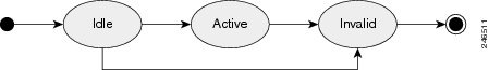
A call abstraction is represented in Figure 1-5 on the voice gateway in one of the following three states:
- IDLE—Initial state of all calls. A call in an idle state has zero connections.
- ACTIVE—Call with ongoing activity. A call in an active state has one or more associated connections.
- INVALID—Final state of all calls. Calls that lose all their connections are moved into this state. A call in the invalid state has zero connections.
Figure 1-5 Call Abstraction Model
XCC Call Media Set Attributes
External applications can enable the voice gateway to detect changes to the call media set attributes on a call and have the voice gateway send a notify event message. Table 1-5 lists the call media set attributes that the gateway can detect.
|
|
|
|---|---|
Enables the voice gateway to detect when a call changes between the following call modes: Note ISDN calls with an unrestricted bearer capability value are reported as data calls. |
|
Enables the voice gateway to detect a DTMF digit in the media stream or a DTMF relay. Note The notify event message includes the timestamp if the DTMF event is detected in IOS. Note For notify event messages, the application should use the voice gateway as the NTP2 server for synchronizing clocks. |
|
Enables the voice gateway to detect when the media activity state changes from “Active” to “Inactive” or vice versa. |
|
Enables the voice gateway to detect the following specified tones: Note Tone detection is not supported for a FXO voice port if the supervisory tone detection feature is enabled. |
|
Enables media forking on a connected call to target a RTP address. For more information on media forking, see the “XCC Call Media Forking” section. |
|
|
XCC Call Media Forking

Note![]() XCC Call Media Forking is not supported in secure mode.
XCC Call Media Forking is not supported in secure mode.
External applications can request media forking for a call. When the application requests media forking, it must provide the XCC provider with two unique remote RTP ports (nearEndAddr and farEndAddr). The XCC provider identifies the incoming connection of a call, forks both the transmit (TX) and receive (RX) packets, and sends the packets to the targeted RTP ports. The XCC provider uses the nearEndAddr element for the forked TX media stream and the farEndAddr XCC element to record the RX media stream. The two forked media streams are sent from the voice gateway in a “SEND ONLY” direction.
Media forking has the following limitations:
- Supports only voice media stream.
- Supports only IPv4 RTP forked media stream.
- Media mixing on forked media streams is not supported.
- Media negotiation is not supported on the forked media streams. In other words, the codec of the forked media stream cannot be changed. If the targeted media server supports a dynamic codec format in the forked media stream, you must configure a supported codec, such as G.711, in the voice gateway.
- Media renegotiation is not supported.
- Media forking ends when the connection is disconnected.
- Supplementary services are not supported.
- Only one media forking request per session is supported. The XCC provider rejects additional media forking request from the application.
- TDM call legs cannot be forked. If CallID is used, it always anchors the fork to the inbound call leg, which must be IP based.
The XCC provider updates the application on the status of the media forking by including one of the following states in the NotifyXccCallData message.
- FORK_FAILED—Setup for media forking failed. Forked RTP connections cannot be established with the targeted RTP addresses.
- FORK_STARTED—Media forking was successful. Both the TX and RX forked RTP connections are established and connected to the targeted RTP addresses.
- FORK_DONE—Media forking has completed. Both the TX and RX forked RTP connections are released.
XCC Connection
The XCC connection describes the relationship in a XCC call and the endpoint or trunk in the call. Figure 1-6 illustrates the connection states.
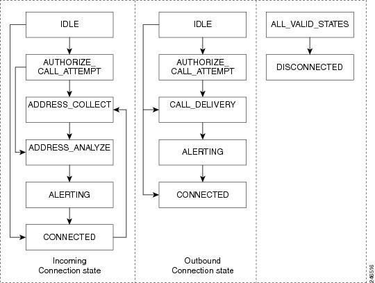
Table 1-6 describes the connection states and the activity and exchanges that can occur between the voice gateway and application when the application sets up event notifications for a particular connection state.
XSVC Provider
The extended serviceability provider (XSVC provider) monitors the health of the trunk and provides the application with real-time trunk status.
The XSVC provider can monitor both traditional public switched telephone network (PSTN) trunks and VoIP trunks. You must configure the XSVC provider and install a route listener for XSVC on the interested trunk group to begin monitoring the trunk status. The route listener communicates with the trunk group resource manager to obtain information on the trunks, including alarm information for T1/E1 trunks.
For PSTN trunks, the trunk group is a logical grouping of interfaces with the same signaling characteristics, such as DS1, FXO, or PRI interfaces. The trunk group can have more than one PRI interface and can also support FXO, but you cannot mix FXO and T1/E1 interfaces. The trunk group resource manager supports the logical configuration of trunk groups.
For VoIP trunks, the trunk manager monitors a VoIP trunks by using Internet Control Message Protocol (ICMP) pings. The trunk manager supports up to 1000 trunks.
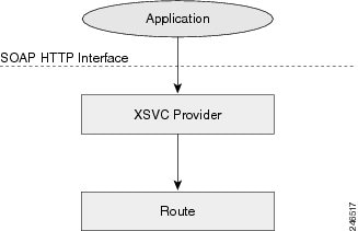
When the application registers with the XSVC provider, the application obtains a handler that the application uses to receive snapshot information on all the routes or specific routes. The XSVC provider can support up to 8 different applications, with each application able to monitor a particular group of trunks.
Figure 1-7 illustrates the relationship between the application, XSVC route, and XSVC provider.
Characteristics of the XSVC Provider
The XSVC provider has the following characteristics:
- When the XSVC provider cannot reach the remote application, the XSVC provider discards event information messages.
- The application must register with the XSVC provider or use a snapshot to obtain the most updated trunk information.
- During the registration, the application can configure event filters for a registered session. The event filters only applies for that registered session.
- The XSVC provider reports on the current status of the trunk. The XSVC provider does not report on changes to a trunk configuration until the change has taken effect.
XSVC Provider API
When the application registers with the XSVC provider, a route listener is installed on the trunk interfaces. If filters are not specified in the registration message, the XSVC provider does not filter out any events. For the application to receive the most current trunk configuration, we recommend that you do not filter out the ROUTE_CONF_UPDATED event.
The XSVC provider API is described in Xsvc Provider Operations.
XSVC Route
With the route snapshot API, the application can request and receive a summary from the voice gateway on all the routes that are currently being monitored in a compact format. The application can also set up a filter to listen to specific routes. The application can also request that the XSVC provider send detail information for a specific route. For T1/E1 trunks, the XSVC provider sends additional information, such as channels, total available channels, alarm, and error statistics.
Alarm Definition
Table 1-7 describes the alarm definition that can be found in XSVC route messages.
|
|
|
|---|---|
Far end LOF3 indication (a.k.a. Yellow Alarm) |
|
Far end sending AIS4 |
|
Far end is sending TS16 LOMF5 |
|
|
|
Statistics Definition
Table 1-7 defines the statistics that are collected and can be found in XSVC route messages.
|
|
|
|---|---|
XCDR Provider
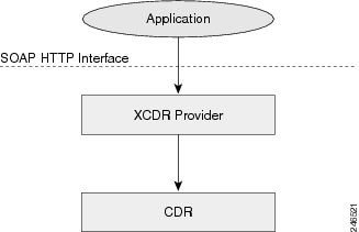
The XCDR provider sends information on a call detail record (CDR) to the registered application when a call ends. The CDR contains statistics on the call and calling party and called party information in a CSV format. The XCDR provider can support up to eight remote application.
When the application registers with the XCDR provider, it obtains a handler that the application can use to receive CDR records. The application can choose to receive either the compact or detailed CDR format.
Note![]() By default, the XCDR provider sends out the CDR record in a compact format to save bandwidth.
By default, the XCDR provider sends out the CDR record in a compact format to save bandwidth.
Figure 1-8 illustrates the relationship between the application, CDR, and XCDR provider.
XCDR Provider API
The XCDR provider API is described in Xcdr Provider Operations.
XCDR CDR is responsible for collecting CDR information and generating events that are sent to the application. The application can specify whether it wants the CDR record in compact or detailed format by using the RequestXcdrSetAttribute message.
Call Detail Record
For detail information on the name and order of the call detail record fields, see CDR Accounting for Cisco IOS Voice Gateways .
XMF Provider
XMF provider gives an application the capability to monitor calls and trigger media forking on the calls and has the capability to service up to 32 applications. The XMF provider can invoke a call-based or a connection-based media forking using the Unified Communications (UC) API. After the media forking is invoked, it can preserve the media forking initiated by the web application if the WAN connection to the application is lost. The XMF provider also provides the recording tone to the parties involved in the call.
The XMF provider API is described in Xmf Provider Operations.
XMF Call-Based Media Forking
In call-based media forking of the gateway, the stream from the calling party is termed as near-end stream and the stream from the called party is termed as far-end stream. The XMF provider actively handles single media forking request per session. Any new media forking request from the external application will override or stop the current forking instance and would start a new forking instance (to the appropriate target IP address or ports). After the media forking request is accepted, the XMF provider returns a response message and starts to fork media streams of a connection to the target forked streams. A NotifyXmfCallData message will be notified to the application for the updated media forking status, that is, FORK-FAILED, FORK_STARTED, or FORK_DONE.
XMF Connection-Based Media Forking
In connection-based media forking of the gateway, the incoming stream to the connection is termed as near-end stream and the outgoing stream of the connection is termed as far-end stream. The XMF provider actively handles single media forking request per session. Any new media forking request from the external application will override or stop the current forking instance and would start a new forking instance (to the appropriate target IP address or ports). After the media forking request is accepted, the XMF provider returns a response message and starts to fork media streams of a connection to the target forked streams.
Figure 1-9 XMF Connection Based Media Forking
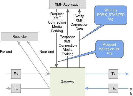
A NotifyXmfConnectionData message will be notified to the application for the updated media forking status:
- FORK_FAILED—Media forking is setup failure. No forked RTP connections can be established to target RTP addresses.
- FORK_STARTED—Media forking is set up successfully. Both Tx (transmit) and Rx (receive) forked RTP connections are established and connected to target (farEnd and nearEnd) RTP addresses.
- FORK_DONE—Media forking is completed. Both Tx and Rx forked RTP connections are released.
XMF Connection
The XMF connection describes the relationship between an XMF call and the endpoint (or trunk) involved in the call. A connection abstraction maintained in the gateway has the following connection states:
Media Forking for SRTP Calls
SRTP forking is supported in XMF and XCC application service providers and the supported APIs are RequestCallMediaForking, RequestCallMediaSetAttributes, and RequestConnectionMediaForking.
SRTP forking is supported for SRTP-to-SRTP, SRTP-to-RTP, and RTP-to-SRTP calls.
- For SRTP-to-SRTP calls, media forking on either leg would result in SRTP streams being forked.
- For SRTP fallback calls, after the initial offer, voice gateway will fall back to RTP. Media forking either call legs would result in RTP streams being forked.
- For SRTP-to-RTP interworking calls, a digital signal processor (DSP) is required and involves transcoding. In this case, one leg would be SRTP and the other leg RTP.
SRTP Crypto keys are notified over the API.
Supports automatic stopping of media forking when stream changes from SRTP or to SRTP.
- The optional mediaForkingReason tag in XMF or XCC Notify messages indicates that the forking has been stopped internally.
- mediaForkingReason tag is only present when the connection changes state, such as mid-call re-INVITE. SRTP stream can change to RTP or SRTP stream can change keys mid-call.
- mediaForkingReason tag is always accompanied by FORK_DONE.
Crypto Tag
For SRTP forking, the optional Crypto tag in NotifyXmfConnectionData or NotifyXmfCallData message indicates the context of an actively forked SRTP connection.
Note![]() The Crypto tag is only present in the notification message where FORK_STARTED tag is present.
The Crypto tag is only present in the notification message where FORK_STARTED tag is present.
The optional Crypto tag specifies the following:
- The Crypto suite used for encryption and authentication algorithm.
- The base64 encoded mastery key and salt used for encryption.
Crypto suite can be one of the two suites supported in IOS:
The following is a sample SDP data sent in an SRTP call:
|
|
|
|---|---|
| o=CiscoSystemsSIP-GW-UserAgent 7826 3751 IN IP4 172.18.193.98 |
o=CiscoSystemsSIP-GW-UserAgent 7826 3751 IN IP4 172.18.193.98 |
Note![]() The application is notified of the content in Crypto and inline SDP lines.
The application is notified of the content in Crypto and inline SDP lines.
Multiple XMF Applications Recording Tone
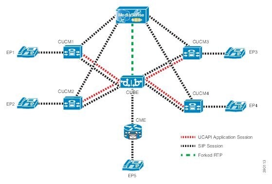
Multiple XMF allows multiple (maximum 32) web applications to register with the XMF provider as separate XMF applications and provide redundancy for the voice calls recording. Recording tone provides recording tone capability to the recording sessions. Recording tone is supported for IP to IP, IP to TDM, and TDM to TDM trunks.
An example topology is as shown below where 4 CUCM applications are deployed. CUCM triggers media forking request to voice gateway. Recording tone is played to the parties involved in the call based on the recordTone parameter set in the media forking request.
Figure 1-10 Multiple XMF Applications and Recording Tone
Media forking can be invoked using any of the following APIs:
The “recordTone” parameter can be enabled in any of the above requests and recording tone will be played for the parties involved in the call. The “recordTone” parameter in the API request can have the following values:
There is no difference in the recording tone beep when any country value is chosen. Recording tone beep is played at an interval of every 15 seconds. Digital signal processors and other resources are not utilized for playing recording tone even for transcoded calls. No specific configuration is required to enable or disable recording tone. By default, no recording tone is enabled.
If “recordTone” parameter is enabled only on the farEndAddr, then this tone is played only on the outgoing leg. Likewise, if enabled only on the nearEndAddr, then the tone is played only on the incoming leg. When enabled in both the far and near end, then recording tone is played on both the legs.
The RequestXmfConnectionMediaForking API allows insertion of recording tone on a per connection basis. There could be scenarios where one leg receives two recordTone insertion requests. When a leg receives recordTone insertion request, the nearEnd request always takes precedence over the farEnd request.
Forking Preservation
After media forking is initiated by the web application, the forking can be preserved to continue the recording, even if the WAN connection to the application is lost or if the application is unregistered.
Figure 1-11 Forking Preservation
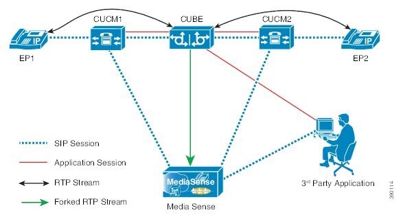
The “preserve” parameter value can be set to TRUE or FALSE in any of the 3 forking requests (RequestXmfConnectionMediaForking, RequestXmfCallMediaForking, or RequestXmfCallMediaSetAttributes) from the application to voice gateway.
- If the “preserve” parameter received is TRUE, then forking will continue the recording, even if the WAN connection to application is lost or application is unregistered.
- If the “preserve” parameter received is FALSE, then forking will not continue the recording.
- If the “preserve” parameter is not received in the media forking request, then forking will not continue the recording.
 Feedback