Access Configuration Manager
Procedure
-
Double-click the Unified CCE Administration Tools folder icon, then double-click the Configuration Manager icon.
-
From the Start menu, select .
The documentation set for this product strives to use bias-free language. For the purposes of this documentation set, bias-free is defined as language that does not imply discrimination based on age, disability, gender, racial identity, ethnic identity, sexual orientation, socioeconomic status, and intersectionality. Exceptions may be present in the documentation due to language that is hardcoded in the user interfaces of the product software, language used based on RFP documentation, or language that is used by a referenced third-party product. Learn more about how Cisco is using Inclusive Language.
Double-click the Unified CCE Administration Tools folder icon, then double-click the Configuration Manager icon.
From the Start menu, select .
When you start the Configuration Manager, the Configuration Manager window appears. The figure following shows the window with the top-level directories displayed for all its menus.
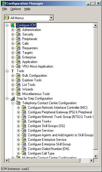
The Configuration Manager lets you view and update configuration information in the Unified ICM database. The configuration information describes the people, groups, and devices that are part of your enterprise.
To set up the configuration of a new system when you are a new user, follow the steps in the menu bar's Step by Step Configuration selection list.
Use the tools in the Telephony Contact Center Configuration menu in the order given to configure, first NICs, then peripherals. After you configure the system software for your telephony contact center, you can configure the software for multimedia applications.
The tools in the MultiMedia Contact Center Configuration menu are also in the order in which you generally use them. For example, you must have a media class before you can create an MRD for that class. And you must have an application instance before you can specify the path to that application.
To access:
The configuration tools according to the menu selections of the former Configure ICM tool, in the menu, select Configure ICM.
All the tools you can use in the Configuration Manager, in the menu bar, select Tools.
For information about any Configuration Manager tools, menu options, or other interface features, refer to the online help.
You can activate help from within the system software in any of three ways:
Click Help in the tool bar or in the dialog
Select from the menu bar
Press the F1 key
Use the menu bar in the Configuration Manager window to select the task or tool you want.
|
Tools |
Description |
||
|---|---|---|---|
|
Enable you to configure multiple records at a time. |
|||
|
Enable you both to view records and their related records and to define, edit, and delete them and their relationships. Explorer tools manage records that have more than one relationship; List tools manage records that have no or only one relationship to other records. |
|||
|
Help you perform configuration tasks for which the previous tools are not appropriate. |
|||
|
Guide you through configuration tasks. |
|||
|
Outbound Option |
Adds outbound dialing functionality to the existing inbound capabilities of the system software.
|
 Note |
Refer to each tool's online help for detailed information. |
Use Configuration Manager's bulk configuration tools to configure multiple records at a time.
The bulk configuration tools enable you to bulk configure the following individual database table records.
The tools are named for the records they manage:
Agents
Call types
Dialed number plans
Dialed numbers
Device targets
Labels
Network trunk groups
Network VRU scripts
Peripheral targets
Person bulk tool
Regions
Region prefixes
Routes
Trunks
Trunk groups
Scheduled targets
Services
Skill groups
VRU port maps
Note |
Refer to each tool's online help for detailed information. |
Use Configuration Manager's Explorer and List tools to configure and manage individual database records.
Use the Explorer tools to configure and manage database records that have hierarchical relationships to other records. In this way, at one time, you can see and update both the individual records and their relationships. You can configure and manage the following records with the Explorer tools.
The tools are named for the type of records they manage:
Agent Explorer
Announcement Explorer
Database lookup Explorer
Device target Explorer
ICM instance Explorer
Network VRU Explorer
Network trunk group Explorer
NIC Explorer
PG Explorer
Region Explorer
Scheduled target Explorer
Service Explorer
Service array Explorer
Skill group Explorer
Translation route Explorer
Note |
Refer to each tool's online help for detailed information. |
Use the list tools to configure and manage database records that have limited or no hierarchical relationship to other records. You can configure and manage the following individual records with the list tools.
The tools are named for the type of records they manage:
Agent desk settings list
Agent targeting rule list
Agent team list
Application gateway list
Application instance list
Bucket intervals list
Business entity list
Call type list
Class security list (on partitioned systems only)
Dialed number/script selector list
Enterprise route list
Enterprise service list
Enterprise skill group list
Expanded call variable list
Expanded call variable payload list
Feature control set list
Label list
Media class list
Media routing domain list
Network VRU script list
Person list
Reason code list
Service level threshold list
Supervisor list
User list
User group list
User variable list
VRU currency list
VRU defaults list
VRU locale list
Note |
Refer to each tool's online help for detailed information. |
The following Configuration Manager tools enable you to do miscellaneous functions not available with the other tools:
Deleted objects: Enables you to view all records deleted from the database and to permanently delete them if you no longer want them.
Integrity check: Allows you to perform specific integrity checks on the configuration data in the Unified ICM database.
Region editor: Allows you to:
View, create, update (cut, copy, paste, move, or edit), and delete custom regions.
View, copy, move, or delete predefined regions, but not edit them.
Script reference: Allows you to generate a report that shows which routing scripts reference a specific configuration record.
System information: Allows you to view and set general and application gateway information about your enterprise.
Unreferenced objects: Lists the database tables that have unreferenced records. Use this tool to find specific integrity problems within the database.
Two wizards guide you through the configuration of:
Translation routes (Translation route wizard)
Call center applications (Application wizard)
Use these wizards for step-by-step guidance.
The Explorer, Bulk, and List tools have the following common features:
Common filter access
To access data from the database, in the Select filter data box of the Bulk, List, or Explorer Configuration Insert tool window, select the type of data you want and click the Retrieve button.
Record status symbols
When you make an edit, the record's status symbol updates accordingly. This appears to the left of the record name in the list box of the Explorer or List tool and in the State column of the bulk tool.
|
Symbol |
Description |
||
|---|---|---|---|
|
|
A green check mark means the object has not changed since you retrieved it from the database or made a save.
|
||
|
|
A red X means the object is marked for deletion and will be deleted when you click the Save button. |
||
|
|
A yellow arrow means that the object's data has been changed and the changes have not yet been saved in the database. |
||
|
|
A yellow addition sign means the object is to be inserted into the database when you click the Save button. |
||
|
|
A red circle with a red slash through it indicates the object was created using an application and is controlled by the application object filter (AOF) or by peripheral auto-configuration. |
Other common features:
ID status box
The label in the ID box at the bottom of the screen identifies the Unified ICM system (instance) on which you are working.
Delete/Undelete button
When a record is selected and you click the Delete button, that button toggles to Undelete and a red X marks the record for deletion. As soon as you save your database changes, marked records are deleted from the database.
Save button
No changes are made to the database until you click the Save button.
The list and Explorer tools share the following features.
List box of retrieved records
Both the Explorer and list tools have a list box that displays retrieved records. Selecting a record in this list displays that record's properties in the right side of the tool window. After the record is displayed, you can edit it if you have maintenance access to it.
Retrieved records:
Tree (only in Explorer tools)
In an Explorer window, the retrieved list is called a directory tree, which you can expand or contract to show a hierarchy of records. A legend above the tree identifies the types of records that you can display in the tree.
With the mouse, you can select a record in a tree and move it to another part of the tree, as long as its object type belongs in that tree location.
UNASSIGNED (only in Explorer tools)
The Explorer tree can also contain UNASSIGNED records. These are stored in an UNASSIGNED directory for the selected directory tree object.
A record is named UNASSIGNED if it was not assigned (mapped) to a parent object. For example, a label created in the bulk configuration tool might not have been assigned to a peripheral target, or a route might not have been assigned to a service.
You can also use the label bulk configuration tool to take the output of a switch and create 20 or 30 labels. Then, using an Explorer tool, you can attach the labels to an appropriate location.
List (only in List tools)
In a list window, the retrieved list is called a list and has no legend above it since its records have no or only one relationship to another record.
Adding new records
The Add button is enabled only after you use the Select filter data section of the window.
In the Explorer tools, when a record in the tree is selected, you can add another record of the same kind or a record immediately below it in the tree hierarchy. In the List tools, the Add button is enabled only for the single type of records listed.
Deleting Records
Selecting a record and clicking Delete marks the record (with a red X) for deletion. However, the record is not deleted until you click Save.
Delete toggles to Undelete when you select an object marked for deletion. To undelete an object marked for deletion, select it and click Undelete.
Options menu
In the Explorer and List tool windows, right clicking on a retrieved record displays an options menu containing all the editing options for that record.
Note |
The options menu is not available in the List tools if you have read-only access. |
The Bulk Configuration, List, and Explorer tools enable you to access records from the database in the same way. In these tools, use the Select filter data box to select and retrieve data from the database. Until you retrieve database data, no data is displayed.
In the top left of the Bulk Configuration Insert, the Explorer, and the List Tool windows is a Select filter data box similar to the following.
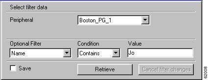
In this example, all records belonging to the Boston_PG_1 peripheral and having Jo in their names are selected for retrieval from the database.
The filters used to select data vary according to the type of data. In the preceding example, data is first selected by peripheral and then by name. Some filter selection boxes have only optional filters.
To achieve maximum response time when retrieving records:
Always select a specific member from the primary filter, even if only one exists. For example, for the Dialed number/script selector list tool, always select a specific routing client and customer. In addition to reducing the number of records loaded and listed, this also improves response time when navigating through the list of records and when adding new ones.
Specify an optional filter whenever possible to further reduce the number of records retrieved. For example, when using the Dialed number/script selector list tool, this could be a Name, Dialed number string, or Description.
Separate the operation of adding records from editing existing records. In addition to selecting the targeted primary filter, specify a unique optional filter for the new record that will result in no existing records being loaded. For example, when using the Dialed number/script selector list tool, specify the exact dialed number string to be added. The retrieval response time will be almost instantaneous and the list of records being added will be easier to manage.
If any editable field is changed, an additional dialog appears (below the Select filter data dialog) displaying the original filter settings. In addition, the Tree List box and all buttons except Retrieve, Close, and Help are disabled.
Clicking Close cancels the filter changes and returns the fields to their original settings. Clicking Retrieve closes the Select filter data dialog and enables the display (in the tree list box) of the record retrieved based on the selected filter criteria.
The following table describes how the optional filters, the check box, and the filter buttons work for all the Bulk Insert, Explorer, and List tools.
|
Filter item |
Function |
|
|---|---|---|
|
Optional filter |
None in the optional filter box means no optional filtering. All data is displayed for the selected records. The optional fields to filter on differ by record type according to both the fields in a record and the fields considered useful as filters. |
|
|
Condition |
If the selected optional filter is |
Then |
|
None |
The Condition filter is ignored. |
|
|
A text filter (for example, description) |
Select one of the text conditions (Contains, Ends With, Starts With, Is Blank) and enter an appropriate entry in the value field. |
|
|
A numeric filter (for example, trunk number) |
Select one of the numeric conditions (Equal, Greater Than, Less Than, Not Equal) and enter an appropriate entry in the value field. The available numeric conditions can change depending on the record data. For example, Equal or Not Equal might be the only choices. |
|
|
Value |
The entry in this field is based on the selections made in the optional filter and condition fields. If None is selected in the optional filter field, this field is ignored. |
|
|
Save check box |
If checked, indicates that the current settings are saved so that when you next open the list tool for this type of record, the current settings will be selected. However, no data is displayed until you click the Retrieve button. |
|
|
Retrieve button |
This button displays the data selected in the Select filter data box. |
|
|
Cancel filter changes button |
If you change the optional filter settings after a retrieve, clicking this button resets the filter settings back to the preceding ones. |
|
The system software saves the configuration data and immediately applies your changes to both the local and central Unified ICM database.
Note |
|
In general, feature control addresses the need of restricting users, or classes of users, from all functionality of the system software. Feature control is a method of security for prohibiting access to the system software features.
Script Editor feature control addresses the need of restricting users, or classes of users, from some or all of the functionality of the Script Editor software. In a possible deployment scenario, a system software administrator can restrict certain people from doing specific types of script editing. Similar functionality was previously available in the system software in the Limited (Single Instance) Administration & Data Servers feature control.
An administrator has two means to restrict access to the editing features of Script Editor and Internet Script Editor:
Edit options
Script node control
It is also possible for an administrator to use a combination of both feature control options.
Refer to the Scripting and Media Routing Guide for Cisco Unified ICM/Contact Center Enterprise for more feature control information.
Script node control allows an administrator to create feature sets that can be assigned to users. The feature set controls which script nodes are accessible to the user.
The node control table (in the Configuration Manager Script Editor Feature Control dialog) has two columns, the Node column and the Available column. This table allows an administrator to create feature control sets that can be assigned to users. The feature control set controls which script nodes are accessible to the user.
If a script is opened that contains a disabled node, you can browse or monitor the script but you cannot put the script into edit mode. If you attempt to put this script into edit mode a message indicating you are not authorized to enter edit mode is displayed. However, you can still Quick Edit the script, just not the node.
A node is an executable element within a script. A script consists of nodes, connections, routing targets, and comments. Every script begins with a Start node. The node column lists of all the nodes that can be used in a script.
Each checked node in the available column appears on the editing pallet of the feature-control-set user, regardless of the edit mode (Full Edit or Quick Edit Only).
There are two possible presentation effects:
Enabled nodes are displayed on the object palette
Disabled nodes are removed from the object palette
Configuring a feature control set consists of:
Creating a feature controls set (see Create a Feature Control Set)
Assigning users to a feature controls set (see Assign Users to a Feature Control Set)
Selecting the script nodes available in a feature controls set (see Select Script Nodes for a Feature Control Set)
The system administrator can create a feature control set using the Configuration Manager on the Unified ICM Administration & Data Server:
|
Step 1 |
Ensure any users to be assigned a feature set are configured. |
|
Step 2 |
Start the Configuration Manager by clicking open . . The Configuration Manager dialog opens. |
|
Step 3 |
Select . |
|
Step 4 |
In the Feature Control Set section (on the left), click Add. |
|
Step 5 |
Select the Attributes tab. |
|
Step 6 |
Enter the name of the feature control set. The name appears in the left section when Enter or Tab is pressed. |
|
Step 7 |
Enter a description (optional). |
The system administrator can assign users to a feature control set:
|
Step 1 |
Start the Configuration Manager by clicking open . . The Configuration Manager dialog opens. |
||
|
Step 2 |
Select . |
||
|
Step 3 |
Select the user to whom a feature control set is to be assigned.
|
||
|
Step 4 |
On the Attribute tab, select the feature set for the selected user. |
||
|
Step 5 |
Click Save when you are finished assigning feature sets. |
To select script nodes:
|
Step 1 |
Select the name of the feature control set to be assigned. |
|
Step 2 |
Select the Attributes tab. |
|
Step 3 |
Select . |
|
Step 4 |
In the Script Editor Feature Control dialog, select the nodes for this feature control set and an edit option (Full Edit or Quick Edit). |
|
Step 5 |
Click OK. |
|
Step 6 |
Click Save. |
After making changes or additions to your configuration, you must always check that the configuration is internally consistent and complete.
Note |
It is especially important to perform integrity checks if you have imported data from another source. |
To check the integrity of your configuration data, perform the following:
|
Step 1 |
In the Configuration Manager, select . The Integrity Check dialog appears. |
|
Step 2 |
Choose the type of check option that you want to perform or click Select All to choose all the check options. (For specific information about each of these options and the tables and fields they check, refer to the Configuration Manager online help.) |
|
Step 3 |
Click Perform Check. The Configuration Manager performs the check and one of the following happens:
|
|
Step 4 |
When all checks are complete, click Close. The Integrity Check dialog closes. |
Many database records need references to related records. For example, each peripheral target must reference a route and each trunk group must reference a network trunk group.
To check record references, perform the following:
|
Step 1 |
In the Configuration Manager menu, select . The Unreferenced Objects dialog appears listing the database tables containing objects that are missing references. |
|
Step 2 |
To see the specific rows that are missing references in a table, double-click on the table name. Double-clicking on a table name entry displays that table showing the records that are missing references. |
At some point, you might want to remove configuration records from your database; for example, if data has been entered in error or changes occur in your business.
To delete a record:
|
Step 1 |
Within Configuration Manager, open any one of the tools in which you can configure that type of record and retrieve the record. |
||
|
Step 2 |
Select the retrieved record. |
||
|
Step 3 |
Click Delete. A red X (marked for deletion) appears in the window next to the name of the record. The Delete button toggles to Undelete. To undelete the record, select it and click Undelete. |
||
|
Step 4 |
Click Save to save the deletion to the database. The record is deleted from the database and is removed from the window.
|
||
|
Step 5 |
Click Save. The deletion is saved to the database and the record disappears from the window. |
Depending on the record involved, the Configuration Manager performs one of two types of deletion:
Immediate deletion. The system software immediately removes the record from the database. (Also known as physical deletion.)
Logical deletion. The system software sets the record's Deleted field to Y (yes), but the record remains in the database. The Configuration Manager and the CallRouter treat the record as though it were deleted. The record remains in the database, however, for historical reporting purposes.
Some tables — for example, the Skill Group Member table, which maps agents to skill groups — do not have a Deleted field. When you delete a record from such a table, the system software immediately removes the record from the central and local database.
Other tables, for example, the Skill Group table, which describes a skill group associated with a peripheral — do have a Deleted field. When you delete a record from such a table, the system software does not remove the record from the central and local database. Instead, the system software sets the record's Deleted field to Y to indicate that it is logically deleted.
Logical deletion ensures that any references to the record — for example, references to a skill group in call detail records — remain valid. However, the Configuration Manager and the Script Editor treat the record as though it were deleted.
 Caution |
Never attempt to set a configuration record's Deleted field directly. Changing a Deleted field directly can compromise the integrity of your Unified ICM database. Use the Configuration Manager option to permanently remove logically deleted records. |
How a configuration tool processes a record deletion request depends on whether, and how, the record is referenced by other configuration records:
If no other records reference the current record, the configuration tool deletes the record.
If other records reference the current record — and the configuration tool can neither modify the references nor delete the other records — the configuration tool does not delete the record.
The Configuration Manager lets you view logically deleted records. It also allows you to permanently delete these records.
To view deleted records, perform the following:
|
Step 1 |
In Configuration Manager menu, select . The Deleted Objects dialog appears, indicating the tables in which records are marked for deletion and the number of records so marked. |
|
Step 2 |
To see the specific records marked for deletion within a table, double-click on a table name. If you double-click on a table name entry, a list window appears showing records from that table that are marked for logical deletion. |
|
Step 3 |
To remove records from the database entirely, select a record from the list (or use the Select All button to select all) and click Delete Permanently. The Configuration Manager displays a message indicating the operation completed. You must have access rights to a record to be able to delete it permanently. |
|
Step 4 |
Click Close to close the dialog. |
You can configure call type intervals in relation to your service levels. For example, if your service level threshold is 15 seconds and you want to see when callers are abandoning within that service level, you can set intervals of 5 seconds, 10 seconds, and 15 seconds.
|
Step 1 |
From the Configuration Manager, open the Call Type List tool. |
|
Step 2 |
Click Add. |
|
Step 3 |
In the Name field of the Attributes tab, assign the new list a name. |
|
Step 4 |
Select the Customer from the pull-down menu. |
|
Step 5 |
Check the Override System Information Default box for the Bucket Intervals section. |
|
Step 6 |
Using the pull-down menu, select the desired Bucket Intervals list. |
Access the Configuration Manager on the Child Administration & Data Server to configure call types.
To configure call types on the Child Central Controller with the Configuration Manager Call Type List Tool:
|
Step 1 |
Start the Call Type List Tool. |
|
Step 2 |
In the Main window of the Call Type List Tool, click Retrieve. |
|
Step 3 |
Click Add. The Call Type Attributes tab appears. |
|
Step 4 |
Set internal_2500CT as the Name, then select bh03 as the Customer setting. |
|
Step 5 |
Click Save. The call type appears in the tree list. |
|
Step 6 |
Repeat this process to add two more call types (internal_2501CT and internal_2502CT). When finished, you have the following call types:
|
|
Step 7 |
Click Save next to the green checkmark, and then Close to exit the Call Type List Tool. |
You cannot assign agents from different peripherals to the same supervisor's team. However, you can create supervisors on multiple peripherals that use the same Person record.
Note |
Use the Select Person drop-down list to create separate supervisors for each peripheral. |
To see all their teams, the supervisor uses a different URL to open the Finesse instance for each peripheral. Open each Finesse instance in a different browser window. Each browser shows only the teams from the Finesse instance that is configured for that peripheral.
 Feedback