High Availability and Network Design

High Availability Designs

Cisco contact center enterprise solutions have high availability features by design. Your solution design must include redundancy for the core components. The redundant components fail over automatically and recover without manual intervention. Your design can include more than that basic high availability capability. A successful deployment requires a team with experience in data and voice internetworking, system administration, and contact center enterprise solution design and configuration.

Each change to promote high availability comes at a cost. That cost can include more hardware, more software components, and more network bandwidth. Balance that cost against what you gain from the change. How critical is preventing disconnects during a failover scenario? Is it acceptable for customers to spend a few extra minutes on hold while part of the system recovers? Would the customer accept losing context for some calls during a failure? Can you invest in greater fault tolerance during the initial design to position the contact center for future scalability?

Plan carefully to avoid redesign or maintenance issues later in the deployment cycle. Always design for the worst failure scenario, with future scalability in mind for all deployment sites.


Note


This guide focuses on design of the contact center enterprise solution itself. Your solution operates in a framework of other systems. This guide cannot provide complete information about every system that supports your contact center. The guide concentrates on the Cisco contact center enterprise products. When this guide discusses another system, it does not offer a comprehensive view. For more information about the complete Cisco Unified Communications product suite, see the Cisco solutions design documents at http://www.cisco.com/en/US/docs/voice_ip_comm/uc_system/design/guides/UCgoList.html.


The following figure shows a fault-tolerant Unified CCE single-site deployment.

Figure 1. Unified CCE Component Redundancy


Note


The contact center enterprise solutions do not support nonredundant (simplex) deployments in production environments. You can only use non-redundant deployments in a testing environment.


This design shows how each component is duplicated for redundancy. All contact center enterprise deployments use redundant Unified CM, Unified CCE, and Unified CVP components. Because of the redundancy, your deployment can lose half of its core systems and be operational. In that state, your deployment can reroute calls through Unified CVP to either a VRU session or an agent who is still connected. Where possible, deploy your contact center so that no devices, call processing, or CTI Manager services are running on the Unified CM publisher.

To enable automatic failover and recovery, redundant components interconnect over private network paths. The components use heartbeat messages for failure detection. The Unified CM uses a cluster design for failover and recovery. Each cluster contains a publisher and multiple subscribers. Agent phones and desktops register with a primary target, but automatically reregister with a backup target if the primary fails.

High Availability and Virtualization

In a virtualized deployment, place the components carefully to maintain high availability. The mechanisms that support high availability are the same. But, distribute the components to minimize multiple failovers from a single failure. When you deploy on Direct Attached Storage (DAS) only systems, consider the following points:

  • Failure of a VM brings down all the components that are installed on the VM.

  • Failure of a physical server brings down all the VMs that are installed on that VMware vSphere Host.

Deployments on systems with shared storage can use some of the VMware High Availability features for greater resiliency. For specific information about supported VMware features, see the Cisco Collaboration Virtualization at http://www.cisco.com/c/dam/en/us/td/docs/voice_ip_comm/uc_system/virtualization/cisco-collaboration-virtualization.html.

To minimize the impact of hardware failures, follow these guidelines:

  • Avoid placing a primary VM and a backup VM on the same physical server, chassis, or site.

  • Avoid placing all the active components in a failover group on the same physical server, chassis, or site.

  • Avoid placing all VMs with the same role on the same physical server, chassis, or site.

Server Failovers

When a server or blade fails over, active calls become inactive and incoming calls are disrupted. Processing resumes when the backup components become active. When the primary server recovers, processing of active and incoming calls returns to the primary server.

Virtualization Do's and Don'ts

Keep the following points in mind when planning your virtualization:

  • Consider which components can be coresident and which components must be coresident on the same VMs. For more information about placement of components in virtual environments, see the virtualization web page for your solution.

  • The contact center enterprise solutions do not support NIC teaming for the Guest OS (Windows or VOS).

  • Set your NIC card and Ethernet switch to autonegotiate.

VMware High Availability Considerations

High availability (HA) provides failover protection against hardware and operating system failures within your virtualized contact center enterprise environment. You can use VMware's HA settings for contact center application VMs only if your solution uses SAN storage.

Consider the following when deploying your solution with VMware HA enabled:

  • Cisco does not support VMware Distributed Resource Scheduler (DRS).

  • In vCenter, select Admission Control Policy > Specify a failover host. When an ESXi host fails, all of the VMs on this host fail over to the reserved HA backup host. The failover host Admission Control Policy avoids resource fragmentation. The Contact Center Enterprise Reference Design models assume a specific VM colocation within your solution. This VM colocation requirement guarantees system performance, based on contact center enterprise capacity requirements.

  • HA Backup hosts must be in the same data center with the primary server, but not in the same physical chassis as the contact center blades. Use 10-GB networking connectivity for vSphere management.

  • In vCenter, select the VM monitoring status > VM Monitoring Only.

  • In vCenter, for the Host Isolation response, select the appropriate option to shutdown all the Virtual Machines.

  • Configure your VMs with the VM restart priority as listed here:

    Table 1. VM Settings

    VM

    VM Restart Priority

    Cisco Unified Intelligence Center

    Low

    Contact Center Management Portal or Contact Center Domain Manager

    Low

    Unified CVP Reporting Server

    Low

    Unified CCE PGs

    Medium

    Cisco Finesse

    Medium

    Unified CVP Servers

    High

    Unified CCE Routers and Loggers

    High

    Cisco IdS

    Medium

    Cisco Unified Call Manager

    High

    Cisco Live Data

    Low

    Cisco Customer Collaboration Platform

    Low

Network Design for Reference Design Compliant Solutions

Tested Reference Configurations

This section provides guidance on the network configuration of UCS deployments. It includes information on fault tolerance and redundancy.

Network Requirements for Cisco UCS B-Series Servers

The following figure shows the virtual to physical communications path from application local OS NICs to the data center network switching infrastructure.

This design uses a single virtual switch with two VMNICs in Active/Active mode. The design has public and private network path diversity aligned through the Fabric Interconnects using the Port Group VMNIC override mechanism of the VMware vSwitch. The design requires path diversity of the public and private networks to avoid failure of both networks from a single path loss through the Fabric Interconnects.

Figure 2. Network Requirements for Cisco UCS B-Series Servers

Contact Center with UCS B Fabric Interconnect requires the following:

  • Fabric must be in end-host Mode.

  • Ethernet interfaces must be 10 GB and connected to Gigabit Ethernet switches.

  • No Fabric Failover must be enabled for vNICs in UCS Manager.


Note


The Nexus 1000v and other Cisco distributed virtual switches based on the Nexus 1000v are not compatible with ESXi 6.5 after Update 1. See the VMware article on the discontinuation of third-party vSwitches for more details.


Data Center Switch Configurations

The contact center enterprise supports several designs for configuring Ethernet uplinks from UCS B-Series Fabric Interconnects to the data center switches. Your design requires Virtual Switch VLAN Tagging. Depending on data center switch capabilities, you can use either EtherChannel / Link Aggregation Control Protocol (LACP) or Virtual PortChannel (vPC).

The required design for public and private network uplinks from UCS Fabric Interconnects uses a Common-L2 design, where both VLANs are trunked to a pair of data center switches. Service Provider also may choose to trunk other management (including VMware) and enterprise networks on these same links, or use a Disjoint-L2 model to separate these networks. Both designs are supported, though only the Common-L2 model is used here.

UCS-C Series

This figure shows the reference design for all solutions on UCS C-series servers and the network implementation of the vSphere vSwitch design.

Figure 3. Network Requirements for Cisco UCS C-Series Servers

This design uses the VMware NIC Teaming (without load balancing) of virtual machine network interface controller (VMNIC) interfaces in an active/standby configuration. It uses alternate and redundant hardware paths to the network.

Your network side implementation can vary from this design. But, it requires redundancy and cannot have single points of failure that affecting both public and private network communications.

Ethernet interfaces must be at least 10 GB speed and connected to Gigabit Ethernet switches.

For more details on UCS C-series networking, see the Cisco Collaboration Virtualization page for your solution at http://www.cisco.com/c/dam/en/us/td/docs/voice_ip_comm/uc_system/virtualization/cisco-collaboration-virtualization.html.

PSTN Network Design Considerations

Highly available contact center designs start with the network infrastructure for data, multimedia, and voice traffic. A "single point of failure" in your network infrastructure devalues any other high availability features that you design into the contact center. Begin from the PSTN and ensure that incoming calls have multiple paths for reaching Unified CVP for initial treatment and queuing.

Ideally, design with at least two SIP trunks each connecting to a separate Cisco Unified Border Element (CUBE). If any CUBE or SIP trunk fails, the PSTN can route all traffic through the remaining SIP trunks. The PSTN route either by configuring all the SIP trunks as a large trunk group or by configuring rerouting or overflow routing to the other SIP trunks. You can also connect a redundant CUBE to each SIP trunk to preserve capacity when a Cisco UBE fails and the SIP trunk is still functional.

In some areas, the PSTN does not provide multiple SIP trunks to a single site. In that case, you can connect the SIP trunk to a Cisco Unified SIP Proxy (CUSP). Then, you could connect multiple CUBEs to the CUSP to provide some redundancy.

The CUBE passes calls to Unified CVP for initial treatment and queuing. Register each CUBE with a separate Unified CVP for load balancing. For further fault tolerance, you can register each CUBE with a different Unified CVP as a backup or configure a SIP Server group in CUBE. If a CUBE cannot connect with a Unified CVP, you can also use TCL scripts to provide some call processing. A TCL script can reroute the calls to another site or dialed number. The script can also play a locally stored .wav file to the caller and end the call.

Figure 4. High Availability Ingress Points

For more information about CUBE, Unified CVP, and voice networks in general, see the Cisco Collaboration System Solution Reference Network Designs at https://www.cisco.com/en/US/docs/voice_ip_comm/uc_system/design/guides/UCgoList.html.

Cisco Unified Survivable Remote Site Telephony (SRST)

Voice gateways using the Cisco Unified Survivable Remote Site Telephony (SRST) option for Unified CM follow a similar failover process. If the gateway is cut off from its controlling subscriber, the gateway fails over into SRST mode. The failover drops all voice calls and resets the gateway into SRST mode. Phones rehome to the local SRST gateway for local call control.

While running in SRST mode, Unified CCE operates as if the agents have no CTI connection from their desktops. The routing application detects the agents as not ready and sends no calls to these agents. When the gateway and subscriber reestablish their connection, the subscriber takes control of the gateway and phones again, allowing the agents to reconnect.

Active Directory and High Availability

Consider the following points that affect high availability when the network link fails between your contact center enterprise setup and Active Directory:

  • Call traffic is not impacted during the link failure.

  • The VMs in the domain restrict sign in using the domain controller credentials. You can sign in using cached credentials.

  • If you stop Unified CCE services before the link fails, you must restore the link before starting the Unified CCE subcomponents.

  • You cannot access the local PG Setup or sign in to the Unified CCE Web Setup.

  • If the link fails while the Unified CCE services are active, access to Unified CCE Web Setup, configuration tools, and Script Editor fails.

  • Although Unified CCMP allow sign in to the portal, access to the reporting page fails.

  • The administrator and super-users can access or configure any attribute, except the Reporting Configuration, in the Cisco Unified Intelligence Center OAMP portal.

  • Supervisors cannot sign in to the Cisco Unified Intelligence Center Reporting portal. However, supervisors who are already signed in can access the reports.

Contact Center Enterprise Network Architecture

Cisco contact center enterprise solutions are distributed, resilient, and fault-tolerant network applications that rely on their network infrastructure meeting real-time data transfer requirements. A properly designed contact center enterprise network requires proper bandwidth, low latency, and a prioritization scheme that favors specific UDP and TCP traffic. The design requirements ensure the fault-tolerant message synchronization between redundant subcomponents. These requirements also ensure the delivery across the system of time-sensitive status data (routing messages, agent states, call statistics, trunk information, and so forth).

In your solution, WAN and LAN traffic comes in the following categories:

Voice and video traffic

Voice calls (voice carrier stream) consist of Real-Time Transport Protocol (RTP) packets that carry the actual voice samples between various endpoints such as PSTN gateway ports, Unified CVP ports, and IP phones. This traffic includes the voice streams for silently-monitored or recorded agent calls.

Call control traffic

Call control traffic includes data packets in several protocols (MGCP or TAPI/JTAPI), depending on the endpoints of the call. Call control includes functions to set up, maintain, tear down, or redirect calls. Call control traffic includes routing and service control messages that route voice calls to peripheral targets (such as agents or services) and other media termination resources (such as Unified CVP ports). Control traffic also includes the real-time updates of peripheral resource status.

Data traffic

Data traffic can include email, web activity, SIP signalling, and CTI database application traffic for the agent desktops. Priority data includes data for non-real-time system states, such as reporting and configuration update events.

This section discusses the data flows between the following:

  • A remote Peripheral Gateway (PG) and the Unified CCE Central Controller (CC)

  • The sides of a PG or a CC redundant pair

  • The desktop application and the Finesse server

For more information on media (voice and video) provisioning, see the Administration Guide for Cisco Unified Contact Center Enterprise at http://www.cisco.com/c/en/us/support/unified-communications/unified-communications-manager-callmanager/products-maintenance-guides-list.html.

Network Link High Availability Considerations

The fault-tolerant architecture employed by Unified CCE requires two independent communication networks. These networks are separate physical networks. The private network carries traffic necessary to maintain and restore synchronization between the components. It also handles client communication through the Message Delivery Subsystem (MDS). The public network (using a separate path) carries traffic between the Central Controllers and PGs. The public network also serves as an alternate network for the fault-tolerance software to distinguish between component failures and network failures. For high availability, include redundant connections in your public network. Ideally, each connection uses a different carrier.


Note


The public network is also called the visible network occasionally.


The figure below illustrates the network segments for a contact center enterprise solution. The redundant pairs of PGs and Central Controllers are geographically separated.

Figure 5. Example of Public and Private Network Segments for a Unified CCE System

In this case, the public network carries traffic between the Central Controller, PGs, and Administration & Data Servers. The public network never carries synchronization control traffic. Public network WAN links must have adequate bandwidth to support the PGs and Administration & Data Servers. You must use either IP-based priority queuing or QoS to ensure that the contact center traffic is processed within acceptable tolerances for both latency and jitter.

The private network carries traffic between the redundant sides of a Central Controller or a PG. This traffic consists primarily of synchronized data and control messages. The traffic also conveys the state transfer necessary to re-synchronize redundant sides when recovering from an isolated state. When deployed over a WAN, the private network is critical to the overall responsiveness of your contact center enterprise solution. The network has aggressive latency requirements. So, you must use either IP-based priority queuing or QoS on the private network links.

To achieve the required fault tolerance, the private WAN link is fully independent from the public WAN links (separate IP routers, network segments or paths, and so forth). Independent WAN links ensure that a single point of failure is truly isolated between the public and the private networks. Deploy public network WAN segments that traverse a routed network so that you maintain the route diversity between the PG and the Central Controller throughout the network. Avoid routes that result in common path selection and a common point of failure for the multiple sessions.

PGs and Administration & Data Servers local to one side of the Central Controller connect to the local Central Controller side through the public Ethernet and to the remote Central Controller side over public WAN links. Optionally, you can deploy bridges to isolate PGs and Administration & Data Servers from the Central Controller LAN segment to enhance protection against LAN outages.

Public Network Traffic Flow

The active PG continuously updates the Central Controller call routers with state information for agents, calls, queues, and so forth. This traffic is real-time traffic. The PGs also send up historical data at intervals based on their configuration. The historical data is low priority, but it must reach the central site before the start of the next interval.

When a PG starts, the central site supplies its configuration data so that it knows which resources to monitor. This configuration download can cause a significant spike in network bandwidth usage.

The public traffic can be summarized as follows:

  • High-priority traffic—Includes routing and Device Management Protocol (DMP) control traffic. It is sent in TCP with the public high-priority IP address.

  • Heartbeat traffic—UDP messages with the public high-priority IP address and in the port range of 39500 to 39999. Heartbeats are transmitted at 400-ms intervals in both directions between the PG and the Central Controller.

  • Medium-priority traffic—Includes real-time traffic and configuration requests from the PG to the Central Controller. The medium-priority traffic is sent in TCP with the public high-priority IP address.

  • Low-priority traffic—Includes historical data traffic, configuration traffic from the Central Controller, and call close notifications. The low-priority traffic is sent in TCP with the public non-high-priority IP address.

Private Network Traffic Flow

The private network carries critical Message Delivery Service (MDS) traffic.

The private traffic can be summarized as follows:

  • High-priority traffic—Includes routing, MDS control traffic, and other traffic from MDS client processes such as the PIM CTI Server, Logger, and so forth. It is sent in TCP with the private high-priority IP address.

  • Heartbeat traffic—UDP messages with the private high-priority IP address and in the port range of 39500 to 39999. Heartbeats are transmitted at 100-ms intervals bi-directionally between the duplexed sides.

  • Medium-priority and low-priority traffic—For the Central Controller, this traffic includes shared data sourced from routing clients as well as (non-route control) call router messages, including call router state transfer (independent session). For the OPC (PG), this traffic includes shared non-route control peripheral and reporting traffic. This class of traffic is sent in TCP sessions designated as medium priority and low priority, respectively, with the private non-high priority IP address.

  • State transfer traffic—State synchronization messages for the Router, OPC, and other synchronized processes. It is sent in TCP with a private non-high-priority IP address.

Merged Network Connections

Unified CCE components use a public network and a private network to communicate. These networks must be separate physical networks. For high availability, include redundant connections in your public network. Ideally, each connection uses a different carrier.

If QoS and bandwidth are configured correctly, your design can merge a public or private WAN link with other corporate traffic. If you use a link that merges non-contact-center traffic, keep the public and private traffic on different networks. However, never split private network traffic onto low-priority and high-priority data paths. The same link must carry all private network traffic for a given component. Sending low-priority and high-priority traffic on different links disables the component failover behavior. Similarly, all low- and high-priority traffic from each peripheral gateway to the low- and high-priority addresses of the call router must take the same path.

During a public network failure, you can temporarily fail over the public Unified CM traffic to the private network. Size the private network to accommodate the extra traffic. When the public traffic fails over to the private network, restore the public network as quickly as possible to return to usual operation. If the private network also fails, your contact center can experience instability and data loss, including the corruption of one Logger database.

IP-Based Prioritization and Quality of Service

Contact center enterprise solutions require QoS on all private networks. On public links, you can use QoS in the 2000 Agent and 4000 Agent Reference Designs. For public links in a 12,000 Agent Reference Design, QoS can delay the detection of server failures.

If large amounts of low-priority traffic get in front of high-priority traffic, the delay can trigger the fault tolerance behavior. To avoid these delays, you need a prioritization scheme for each of the WAN links in the public and private networks. Contact center enterprise solutions support IP-based prioritization and QoS.

In a slow network flow, the time a single large (for example, 1500-byte) packet consumes on the network can exceed 100 ms. This delay would cause the apparent loss of one or more heartbeats. To avoid this situation, the contact center uses a smaller Maximum Transmission Unit (MTU) size for low-priority traffic. This allows a high-priority packet to get on the wire sooner. (MTU size for a circuit is calculated based on the circuit bandwidth, as configured at PG setup.)

An incorrectly prioritized network generally leads to call time-outs and loss of heartbeats. The problems increase as the application load increases or when shared traffic is placed on the network. You can also see application buffer pool exhaustion on the sending side, due to extreme latency conditions.

Contact center enterprise solutions use three priorities: high, medium, and low. Without QoS, the network recognizes only two priorities identified by source and destination IP address (high-priority traffic sent to a separate IP destination address) and, for UDP heartbeats, by a specific UDP port range. IP-based prioritization configures IP routers with priority queuing to give preference to TCP packets with a high-priority IP address and to UDP heartbeats over the other traffic. When using this prioritization scheme, 90% of the total available bandwidth is granted to the high-priority queue.

A QoS-enabled network applies prioritized processing (queuing, scheduling, and policing) to packets based on QoS markings as opposed to IP addresses. The contact center provides a marking capability of Layer-3 DSCP for private and public network traffic. Traffic marking implies that configuring dual IP addresses on each Network Interface Controller (NIC) is no longer necessary because the network is QoS-aware. However, if you mark the traffic at the network edge instead, you still require dual-IP configuration to differentiate packets by using access control lists based on IP addresses.


Note


Layer-2 802.1p marking is also possible if Microsoft Windows Packet Scheduler is enabled (for PG/Central Controller traffic only). However, this is not supported. Microsoft Windows Packet Scheduler is not suited to Unified CCE. 802.1p markings are not widely used, nor are they required when DSCP markings are available.


For more information about proper network design for data traffic, see the network infrastructure and Quality of Service (QoS) documentation at http://www.cisco.com/c/en/us/solutions/enterprise/design-zone-borderless-networks/index.html.

UDP Heartbeat and TCP Keep-Alive

The UDP heartbeat design detects if a public network link has failed. Detection can be made from either end of the connection, based on the direction of heartbeat loss. Both ends of a connection send heartbeats at periodic intervals (every 400 milliseconds) to the opposite end. Each end looks for analogous heartbeats from the other. If either end does not receive a heartbeat after five times the heartbeat period, that end assumes that something is wrong and the application closes the socket connection. At that point, a TCP Reset message is typically generated from the closing side. Various factors can cause loss of heartbeats, such as:

  • The network failed.

  • The process sending the heartbeats failed.

  • The VM with the sending process is shut down.

  • The UDP packets are not properly prioritized.

There are several parameters associated with heartbeats. In general, leave these parameters set to their system default values. Some of these values are specified when a connection is established. Other parameters can be set in the Windows registry. The two values of most interest are:

  • The amount of time between heartbeats

  • The number of missed heartbeats (currently hard-coded to five) that indicate a failure

The default value for the private heartbeat interval between redundant components is 100 milliseconds. One side can detect the failure of the circuit or the other side after 500 ms. The default heartbeat interval between a central site and a peripheral gateway is 400 ms. In this case, it takes 2 seconds to reach the circuit failure threshold.

The contact center enterprise QoS implementation uses a TCP keep-alive message to replace the UDP heartbeat. The public network interface enforces a consistent heartbeat or keep-alive mechanism. But, the private network interface enforces the keep-alive. When QoS is enabled on the public network interface, a TCP keep-alive message is sent; otherwise UDP heartbeats are retained.

The TCP keep-alive feature, provided in the TCP stack, detects inactivity and then causes the server or client side to terminate. The TCP keep-alive feature sends probe packets across a connection after the connection is idle for a certain period. The connection is considered down if a keep-alive response from the other side is not heard. On a Windows server, you can specify keep-alive parameters on a per-connection basis. For contact center enterprise public connections, the keep-alive timeout is set to (5 * 400) ms, matching the failure detection time of 2 seconds with the UDP heartbeat.

Our reasons for moving to TCP keep-alive with QoS enabled are:

  • In a converged network, router algorithms to handle network congestion conditions can have different effects on TCP and UDP. As a result, delays and congestion experienced by UDP heartbeat traffic can result in connection failures from timeouts.

  • The use of UDP heartbeats creates deployment complexities in a firewall environment. With the dynamic port allocation for heartbeat communications, you open a large range of port numbers which weakens the security of your firewall.


Note


You cannot use WAN accelerators on a WAN that carries contact center traffic. WAN accelerators can send signals that effectively disable the failure detection function.


HSRP-Enabled Networks

If your solution network uses the Hot Standby Router Protocol (HSRP) on the default gateways, follow these requirements:

  • Set the HSRP hold time and its associated processing delay lower than five times the heartbeat interval (100 ms on the private network and 400 ms on the public network). This level avoids private network communication outage during the switch-over of the HSRP active router.

    With convergence delays that exceed private or public network outage notification, HSRP failover times can exceed the detection threshold and result in a failover. If the HSRP configuration has primary and secondary designations and the primary path router fails over, HSRP reinstates the primary path when possible. That reinstatement can lead to a second outage detection.

    Do not use primary and secondary designations with HSRP convergence delays near 500 ms for the private network and 2 seconds for the public network. However, convergence delays below the detected threshold (which result in HSRP failovers that are transparent) do not mandate a preferred path configuration. This approach is preferable. Keep enabled routers symmetrical if path values and costs are identical. However, if available bandwidth and cost favor one path (and the path transition is transparent), then designation of a primary path and router is advised.

  • Our fault-tolerant design requires that the private network is physically separate from the public network. Therefore, do not configure HSRP to fail over one type of network traffic to the other network link.

  • The bandwidth requirement for the contact center must always be guaranteed with HSRP, otherwise the system behavior is unpredictable. For example, if you configure HSRP for load sharing, ensure that sufficient bandwidth remains on the surviving links in the worst-case failure situations.

Unified CCE Failovers During Network Failures

Network failures simultaneously affect any components that send traffic across the affected network. Unified CCE subcomponents use both private and public network links to communicate.

The traffic on the private network performs these functions:

  • State transfer during component startup

  • Synchronization of redundant pairs of Routers

  • Synchronization of redundant Logger databases

  • Synchronization of redundant pairs of PGs

The public network carries the rest of the traffic between the subcomponents: voice data, call context data, and reporting data. The public network includes all the public network links between the Unified CCE subcomponents.


Note


In virtualized contact centers, network failures can arise from failures in the virtual environment, like a virtual NIC, or from failures of physical resources.


Response to Private Network Failures

When a private network fails, the contact center quickly enters a state where one or both sides transition into isolated-enabled operation. The isolated operation continues until the Routers detect the restoration of the private network. The redundant pairs of Routers and PGs then resynchronize and resume usual operation.

Assume that Router A is the pair-enabled side and Router B is the pair-disabled side. When the private network fails, the Router A behaves as follows:

  • If Router A has device majority, it transitions to the isolated-enabled state and continues handling traffic.

  • If Router A does not have device majority, it transitions to the isolated-disabled state and stops processing traffic.

When the private network fails, Router B behaves as follows:

  • If Router B does not have device majority, it transitions to the isolated-disabled state and does not process traffic.

  • If Router B does have device majority, it enters a test state. Router B instructs its enabled PGs to contact Router A over the public network. Then, Router B responds as follows:

    • If no PG can contact Router A to determine its state, Router B transitions to the isolated-enabled state and begins handling traffic. This case can result in both Router A and Router B running in isolated-enabled state.

    • If any PG contacts Router A and finds it in the isolated-disabled state, Router B transitions to the isolated-enabled state and begins handling traffic.

    • If any PG contacts Router A and finds it in the isolated-enabled state, Router B transitions to the isolated-disabled state and does not process traffic.

During the Router failover processing, any Route Requests for the Router are queued until the surviving Router is in isolated-enabled state. A Router failure does not affect any in-progress calls that have already reached a VRU or an agent.

The corresponding Logger shuts down when its Router goes idle. Each Logger communicates only with its own Router. If the private network connection is restored, the isolated-enabled Router's Logger uses its data to resynchronize the other Logger. The system automatically resynchronizes the Logger configuration database if the private network connection is brought back up before the 14 day retention period of the Config_Message_Log table. And, if the private network connection remains down for more than the 14 day retention period, you must resynchronize the configuration data on Loggers using the Unified ICMDBA application as described in the Administration Guide, at https://www.cisco.com/c/en/us/support/customer-collaboration/unified-contact-center-enterprise/products-maintenance-guides-list.html.

In each redundant pair of PGs, there is also an enabled PG and a disabled PG. At system start, the first PG to connect becomes the enabled PG. However, after a private network failure, the PG with the greatest weight in the redundant pair becomes the enabled PG. The other PG becomes the disabled PG.

Response to Public Network Failures

Highly available networks generally include redundant channels for the public network. When one channel fails, the other channel takes over seamlessly. The contact center detects a public network failure only when all channels fail between two subcomponents.


Note


In contact centers without redundant public networks, the contact center detects a failure when the single channel fails.


How the contact center responds to a public network failure depends on number and function of the sites and how the sites are linked. The following sections look at some of the more common or significant scenarios.

Failures between Unified Communication Managers

The scenario that can cause the most problems involves the Unified CM subscribers losing their public link. Because the functioning private network keeps the Routers and Agent PGs in synch, the Routers can still detect all agent devices. In this situation, a Router can assign a call to an agent device that is registered on the subscriber on the other side of the public network failure. However, the local CVP cannot pass the connection information to the agent device on the other side of the public network failure. The call fails, but the routing client marks the call as routed to the agent device on the remote subscriber.

Failures in Clustering over the WAN
Failures between Sites

In the clustering over the WAN topology, you need a highly available, highly resilient WAN with low latency and sufficient bandwidth. The public network is a critical part of the contact center’s fault tolerance. A highly available WAN is fully redundant with no single points of failure, usually across separate carriers. During a partial failure of the WAN, the redundant link needs the capability to handle the full load for the sites within the QoS parameters. As an alternative to redundant WANs, you can employ Metro Area Networks (MAN), Dense Wavelength Division Multiplexing (DWDM), or Ethernet WANs. For more information about designing highly available, highly resilient WANs, see Design Zone for Branch WAN at https://www.cisco.com/c/en/us/solutions/enterprise/design-zone-branch-wan/index.html in the Cisco Design Zone.


Note


You cannot use a Wireless WAN, like WiMAX, Munincipal Wi-Fi, or VSAT, for you contact center enterprise solution.


If the public network fails between the sites, the system responds in this manner:

  1. The Unified CM subscribers detect the failure. The subscribers continue to function locally with no impact to local call processing and call control. However, any calls that were set up over the public network fail.

  2. The Routers and PGs detect the failure. The PGs automatically realign their data communication stream to their local Router. The local Router then passes data to the Router on the other side over the private network to continue call processing. The altered data path does not cause a failover of the PG or the Router.

The impact of the public network failure on agents depends on where their phones and desktops registered:

  • The most common case is that the agent desktop and agent phone are both registered to the PG and a subscriber on the same side (Side A for example). When the public link between the sites fails, the agent can continue handling calls usually.

  • In some cases, the agent desktop (Side A for this example) and the agent phone (Side B for this example) can end up registered on different sides. In those cases, the CTI Manager directs phone events over the public network to the PG on the opposite side. When the public network between the sites fails, the phone does not rehome to Side A of the cluster. The phone remains operational on Side B. The PG on Side A cannot detect this phone. Because the Unified CCE subcomponents can no longer direct calls to the agent phone, Unified CCE automatically signs out the agent.

  • Usually, the redundant desktop server pair load balances agent desktop connections. So, half of the desktops register on a desktop server that connects to a PG with an active CTI Server across the public network. When the public network fails, the desktop server loses connection with the remote CTI Server. The desktop server disconnects the active agent desktops to force them to rehome to the redundant desktop server at the remote site. The agent desktop automatically uses the redundant desktop server. The agent desktop remains disabled until it connects to the redundant desktop server.

Failures to Agent Sites

The contact center enterprise topology for clustering over the WAN assumes that the agents are remotely located at multiple sites. Each agent site requires access to both sites through the public network for redundancy. In a complete network failure, these connections also provide basic SRST functionality, so that the agent site can still make emergency (911) calls.

If the agent site loses the public network connection to one of the sites, the system responds in this manner:

  1. Any IP phones that are homed to the Unified CM subscribers at the disconnected site automatically rehome to subscribers at the othersite. To use the rehoming behavior, configure a redundancy group.

  2. Agent desktops that are connected to the desktop server at that disconnected site automatically realign to the redundant server at the other site. (Agent desktops are disabled during the realignment process.)

If the agent site loses the public network connection to both of the sites, the system responds in this manner:

  1. The local Voice Gateway (VG) detects the failure of the communications path to the cluster. The VG then goes into SRST mode to provide local dial-tone functionality.

  2. With Unified CVP, the VGs detect the loss of connection to the Unified CVP Server. Then, the VGs run their local survivability TCL script to reroute the inbound calls.

  3. If an active call came in to the disconnected agent site on a local PSTN connection, the call remains active. But, the PG loses access to the call and creates a TCD record.

  4. The Finesse server detects the loss of connectivity to the agent desktop and automatically signs the agent out of the system. While the IP phones are in SRST mode, they cannot function as contact center enterprise agents.

Response to Failures of Both Networks

Individually, parts of the public and private networks can fail with limited impact to the agents and calls. However, if both of these networks fail at the same time, the system retains only limited functionality. This failure is considered catastrophic. You can avoid many such failures by careful WAN design with built-in backup and resiliency.

A simultaneous failure of both networks within a site shuts down the site.

If both the public and private networks simultaneously fail between two sites, the system responds in this manner:

  1. Both Routers check for device majority. Each router enters isolated-enabled mode if the router has device majority or isolated-disabled mode if the router does not have device majority.

  2. The PGs automatically realign their data communications, if necessary, to their local Router. A PG that cannot connect to an active Router becomes inactive.

  3. The Unified CM subscribers detect the failure and continue to function locally with no impact to local call processing and call control.

  4. Any in-progress calls that are sending active voice path media over the public WAN link fail with the link. When the call fails, the PG creates a TCD record for the call.

  5. In a clustering over the WAN topology, the Unified CM subscribers on each side operate with access only to local components.

  6. The call routing scripts automatically route around the off-line devices using peripheral-on-line status checks.

  7. Agents with both their phones and desktops registered with local Unified CM subscribers are not affected. All other agents lose some or all functionality while their phones and desktops rehome. Those agents might also find themselves signed out, depending on the exact system configuration.

  8. Unified CCE does not route new calls that come into the disabled side. But, you can redirect or handle those calls with the standard Unified CM redirect on failure for their CTI route points or with the Unified CVP survivability TCL script in the ingress Voice Gateways.

Ingress, Egress, and VXML Gateway High Availability Considerations

Highly available contact center designs start with the network infrastructure for data, multimedia, and voice traffic. A "single point of failure" in your network infrastructure devalues any other high availability features that you design into the contact center. Begin from the PSTN and ensure that incoming calls have multiple paths for reaching Unified CVP for initial treatment and queuing.

Ideally, design with at least two SIP trunks each connecting to a separate Cisco Unified Border Element (CUBE). If any CUBE or SIP trunk fails, the PSTN can route all traffic through the remaining SIP trunks. The PSTN route either by configuring all the SIP trunks as a large trunk group or by configuring rerouting or overflow routing to the other SIP trunks. You can also connect a redundant CUBE to each SIP trunk to preserve capacity when a Cisco UBE fails and the SIP trunk is still functional.

In some areas, the PSTN does not provide multiple SIP trunks to a single site. In that case, you can connect the SIP trunk to a Cisco Unified SIP Proxy (CUSP). Then, you could connect multiple CUBEs to the CUSP to provide some redundancy.

The CUBE passes calls to Unified CVP for initial treatment and queuing. Register each CUBE with a separate Unified CVP for load balancing. For further fault tolerance, you can register each CUBE with a different Unified CVP as a backup. If a CUBE cannot connect with a Unified CVP, you can also use TCL scripts to provide some call processing. A TCL script can reroute the calls to another site or dialed number. The script can also play a locally stored .wav file to the caller and end the call.

Figure 6. High Availability Ingress Points

For more information about CUBE, Unified CVP, and voice networks in general, see the Cisco Collaboration System Solution Reference Network Designs at http://www.cisco.com/en/US/docs/voice_ip_comm/uc_system/design/guides/UCgoList.html.

Cisco Unified Survivable Remote Site Telephony (SRST)

Voice gateways using the Cisco Unified Survivable Remote Site Telephony (SRST) option for Unified CM follow a similar failover process. If the gateway is cut off from its controlling subscriber, the gateway fails over into SRST mode. The failover drops all voice calls and resets the gateway into SRST mode. Phones rehome to the local SRST gateway for local call control.

While running in SRST mode, Unified CCE operates as if the agents have no CTI connection from their desktops. The routing application detects the agents as not ready and sends no calls to these agents. When the gateway and subscriber reestablish their connection, the subscriber takes control of the gateway and phones again, allowing the agents to reconnect.

High Availability for Ingress and Egress Gateways

The ingress gateway accepts calls from the PSTN and directs them to Unified CVP for VRU treatment and call routing. The same gateway can act as an egress gateway in certain call flows.


Note


The ingress gateway is sometimes called the originating gateway.


In the contact center enterprise Reference Designs, the ingress gateway uses SIP to communicate with Unified CVP. The SIP protocol does not have built-in redundancy features. SIP relies on the gateways and call processing components for redundancy. You can use the following techniques to make call signalling independent of the physical interfaces. If one interface fails, the other interface handles the traffic.

Dial-Peer Binding

With dial-peer level bind, you set up a different bind for each dial peer. You do not need to have a single interface that is reachable from all subnets. The dial peer helps to segregate the traffic from different networks (for example, the SIP trunk from service provider and the SIP trunk to Unified CM or CVP). This example shows a dial peer level binding:

  Using voice-class sip bind 
   dial-peer voice 1 voip
   voice-class sip bind control source-interface GigabitEthernet0/0

Global Binding

For other gateways, you can use global binding. Connect each gateway interface to a different physical switch to provide redundancy. Each gateway interface has an IP address on a different subnet. The IP routers use redundant routes to the loopback address, either by static routes or by a routing protocol.

You can use a routing protocol to review the number of routes that are exchanged with the gateway. In that case, use filters to limit the routing updates. Have the gateway only advertising the loopback address and not advertise the receiving routes. Bind the SIP signaling to the virtual loopback interface, as shown in this example:

  voice service voip
   sip
    bind control source-interface Loopback0
    bind media source-interface Loopback0

Call Survivability During Failovers

If the gateway fails, the following conditions apply to call disposition:

  • Calls in progress— The PSTN switch loses the D-channel to all T1/E1 trunks on this gateway. The active calls cannot be preserved.

  • Incoming calls— The PSTN carrier directs the calls to a T1/E1 at an alternate gateway. The PSTN switch has to have its trunks and dial plan properly configured.

High Availability for VXML Gateways

The VXML Gateway parses and renders VXML documents from the Unified CVP VXML Servers or an external VXML source. Rendering a VXML document can include the following:

  • Retrieving and playing prerecorded audio files

  • Collecting and processing user input

  • Connecting to an ASR/TTS Server for voice recognition and dynamic text-to-speech conversion.

You cannot have a load balancer on the path between the VXML Gateway and the Unified CVP Call Server.

In topologies that separate the ingress gateway from the Unified CVP Call Server, colocate the VXML Gateway at the Call Server site. This arrangement keeps the media stream from using bandwidth across the WAN.

If the VXML Gateway fails, calls are affected as follows:

  • Calls in progress—The ingress gateway's survivability features route calls in progress to an alternate location by default.

  • Incoming calls—Incoming calls find an alternate VXML gateway.

CVP High Availability Considerations

The Contact Center Enterprise Reference Designs use Unified CVP for the call treatment and queuing. CVP uses SIP for the call control, rather than relying on Unified CM for JTAPI call control.

Figure 7. Unified CVP High Availability Deployment


Unified CVP can use the following system components:

  • Cisco Unified Border Element (CUBE) supports the transition to SIP trunking. CUBE provides interworking, demarcation, and security services between the PSTN and your contact center.

  • Cisco Voice Gateway (VG) terminates TDM PSTN trunks to transform them into IP-based calls on an IP network. Unified CVP uses specific Cisco IOS Voice Gateways that support SIP to enable more flexible call control. VGs controlled by Unified CVP can also use the Cisco IOS built-in Voice Extensible Markup Language (VXML) Browser to provide the caller treatment and call queuing. CVP can also leverage the Media Resource Control Protocol (MRCP) interface of the Cisco IOS VG to add automatic speech recognition (ASR) and text-to-speech (TTS) functions.

  • The CVP Server provides call control signaling when calls are switched between the ingress gateway and another endpoint gateway or a Unified CCE agent. The CVP Server also provides the interface to the Unified CCE VRU Peripheral Gateway (PG). The CVP Server translates specific Unified CCE VRU commands into VXML code for rendering on the VG. The CVP Server can communicate with the gateways using SIP as part of the solution. For high availability discussions, you can view the CVP Server as these subcomponents:

    • SIP Service—Responsible for all incoming and outgoing SIP messaging and SIP routing.


      Note


      You can configure the Call Server to use a SIP Proxy Server for outbound dial plan resolution. SIP Proxy Server minimizes the configuration overhead.

      You can also configure it to use static routes based on an IP address or DNS SRV. Call Servers do not share configuration information about static routes. When you change a static route, you must change it on each Call Server's SIP Service.


    • ICM Service—Responsible for the interface to ICM. The ICM Service communicates with the VRU PG using GED-125 to provide ICM with IVR control.

  • The CVP Media Server acts as a web server that provides predefined audio files to the voice browsers as part of their VXML processing. You can cluster media servers using the Cisco Content Services Switch (CSS) products. With clustering, you can pool multiple media servers behind a single URL for access by all the voice browsers.

  • The CVP Server hosts the Unified CVP VXML runtime environment. The VXML service creation environment uses an Eclipse toolkit browser in the CVP Call Studio application. The runtime environment runs the dynamic VXML applications and processes Java and Web Services calls for external systems and database access.

  • Cisco Unified SIP Proxy (CUSP) servers that are used with CVP can select voice browsers and associate them with specific dialed numbers. When a call comes into the network, the VG queries the Unified SIP Proxy to determine where to send the call based on the dialed number.


Important


Contact center enterprise solutions do not support Unified CM's intercluster Enhanced Location Call Admission Control (ELCAC) feature.


These methods can increase the high availability of CVP:

  • To provide the automatic call balancing across the CVP Servers, add redundant CVP Servers under control of the Unified CCE PGs.

  • To handle conditions where the gateway cannot contact the CVP Server, add survivability TCL scripts to the gateway. For example, you can redirect calls to another CVP Server on another CVP-controlled gateway.

  • To load balance the audio file requests across multiple CVP Media Servers and VXML URL access across multiple servers, add a Cisco Content Server.

This figure shows a high-level layout for a fault-tolerant Unified CVP system. Each component in the Unified CVP site is duplicated for redundancy. The quantity of each of these components varies based on the expected busy hour call attempts (BHCA) for a particular deployment.

Figure 8. Redundant Unified CVP System


The two switches shown in the figure provide the network redundancy for the Unified CVP Servers. If one switch fails, only a subset of the components becomes inaccessible. The components that are connected to the remaining switch are still accessible for the call processing.

High Availability Factors to Balance

You can make your contact center enterprise solution more highly available by adding the following components and subcomponents for CVP:

  • Multiple gateways, Unified CVP Servers, Unified CVP VXML Servers, and VRU PGs—Enables inbound and outbound call processing and VRU services to continue during individual component failures.

  • Unified CVP Media Servers—The VVoice Browser sends requests to the backup media server if the primary media server is unreachable. Ensure that Whisper Announcement and Agent Greeting audio files are duplicated on all media servers for proper failover behavior.

  • Multiple call processing locations—Enables call processing to continue if a call processing location goes dark.

  • Redundant WAN links—Enables Unified CVP call processing to occur if individual WAN links fail.

Call Survivability During Failovers

The following sections describe how the failure of contact center enterprise components and CVP subcomponents affect the call survivability.

Voice Browser

The Voice Browser parses and renders VXML documents obtained from one or several sources. If the VXML gateway fails, the following happens:

  • Calls in progress—The ingress gateway's survivability features route calls in progress to an alternate location by default.

  • Incoming calls—Incoming calls find an alternate VXML gateway.

Unified CVP IVR Service—The CVP IVR Service creates the VXML pages that implement the Unified CVP Micro applications. The micro applications are based on RunExternalScript instructions that are received from Unified CCE. If the IVR Service fails, the following happens:

  • Calls in progress—Calls in progress are routed by default to an alternate location by survivability on the originating gateway.

  • Incoming calls—Incoming calls are directed to an in-service IVR Service.

Unified CM

The CVP Call Server recognizes when the Unified CM fails and the following happens:

  • Calls in progress—The server assumes that it should preserve the active calls, and maintains the signaling channel to the originating gateway. The originating gateway is not aware that Unified CM has failed. More activities in the active calls (such as hold, transfer, or conference) are not possible. After the call ends, the phone routes to another Unified CM server.

  • Incoming calls—Incoming calls are directed to an alternate Unified CM server in the cluster.

CVP Call Server

The CVP Call Server contains the following services which handle call survivability during failovers.

  • Unified CVP SIP Service—The CVP SIP Service handles all incoming and outgoing SIP messaging and SIP routing. If the SIP Service fails, the following happens:

    • Calls in progress—If the CVP SIP Service fails after the caller is transferred (including transfers to an IP phone or Voice Browser), then the call continues usually. But, the CVP SIP Service cannot transfer that call again. If the failure happens before the caller is transferred, then the default survivability routing transfers the call to an alternate location.

    • Incoming calls—Unified SIP Proxy directs incoming calls to an alternate Unified CVP Call Server. If no Call Servers are available, the call is default-routed to an alternate location by survivability.

CVP Media Server

Store the audio files locally in flash memory on the VXML gateway or on an HTTP or TFTP file server. Audio files stored locally are highly available. However, HTTP or TFTP file servers provide the advantage of centralized administration of audio files.

If the media server fails, the following happens:

  • Calls in progress—Calls in progress recover automatically. The high-availability configuration techniques make the failure transparent to the caller. If the media request fails, use scripting techniques to work around the error.

  • Incoming calls—Incoming calls are directed transparently to the backup media server, and service is not affected.


Note


You can locate the Media Server across a WAN from the VXML Gateway. If the WAN connection fails, the gateway continues to use prompts from the gateway cache until the requested prompt expires. The gateway then attempts to reacquire the media, and the call fails if survivability is not enabled. If survivability is enabled, the calls are default-routed.


CVP VXML Server

The Unified CVP VXML Server runs advanced VRU applications by exchanging VXML pages with the Voice Browser. If the CVP VXML Server fails, the following happens:

  • Calls in progress—You can recover calls in progress in a Unified CCE-integrated deployment with scripting techniques. For example, configure the script to first connect to Unified CVP VXML Server A. If the application fails out the X-path of the Unified CVP VXML Server ICM script node, try Unified CVP VXML Server B.

  • Incoming calls—Incoming calls are directed transparently to an alternate CVP VXML Server.

CVP Reporting Server

Failure of a CVP Reporting Server has no impact on call survivability.

The Reporting Server does not perform any database administrative and maintenance activities such as backups or purges. However, the Unified CVP provides access to such maintenance tasks through the Operations Console. The single CVP Reporting Server does not necessarily represent a single point of failure. Data safety and security are provided by the database management system. Temporary outages are tolerated due to persistent buffering of information on the source components.

Custom Remote Code Server

Multiple instances of custom remote code servers can be deployed and load balancing of remote servers can be done using the VXML servers via internal load balancing, or external load balancers, or via a proxy. Individual RPC's can be run in the micro service level or the whole session can be run on the same server in a round robin fashion using the Call Studio application remote URL configuration.

More Call Survivability Points

Consider the following points when you plan for call survivability in your solution:

  • There are scenarios in which call recovery is not possible during a failure:

    • Someone stops the process with calls in progress. For example, a system administrator forgets to do a Call Server graceful shutdown. In this case, the CVP Call Server terminates all active calls to release the licenses.

    • The Call Server exceeds the recommended call rate. There is a limit for the number of calls allowed in the Call Server. But, there is no enforced limit for the call rate. In general, exceeding the recommended calls per second (CPS) for a long period can cause erratic and unpredictable call behavior. Size your solution correctly and balance the call load appropriately across each call processing component.

  • Configure the originating gateways for call survivability as described in the Configuration Guide for Cisco Unified Customer Voice Portal at http://www.cisco.com/c/en/us/support/customer-collaboration/unified-customer-voice-portal/products-installation-and-configuration-guides-list.html. The survivability.tcl script also contains some directions and useful information.

  • You can detect calls that are cleared without Unified CVP’s knowledge:

    • Unified CVP checks every 2 minutes for inbound calls that have a duration older than a configured time (the default is 120 minutes).

    • For those calls, Unified CVP sends an UPDATE message. If the message receives a rejection or is undeliverable, then the call is cleared and the license released.

  • The CVP SIP Service can also add the Session expires header on calls so that endpoints can perform session refreshing on their own. RFC 4028 (Session Timers in the Session Initiation Protocol) contains more details on the usage of Session expires with SIP calls.

  • During failovers, calls under Unified CVP control get treatment from the survivability TCL script in their ingress Voice Gateways. In these cases, the routing dialog in the Unified CCE Central Controller stops. If the survivability scripts redirect the calls to another active Unified CCE component, the call appears as a "new call" to the system with no relationship to the original call for reporting or tracking purposes.

SIP Proxy Servers with CVP

The SIP Proxy Server provides the dial plan resolution for the SIP endpoints. You can configure the dial plan information in a central place, instead of statically on each SIP device. You do not need a SIP Proxy Server in your solution. Consider one for the centralized configuration and maintenance benefits. By deploying multiple SIP Proxy Servers, you can achieve load balancing, redundancy, and regional SIP call routing services. Your solution has the following choices for SIP call routing.

SIP Proxy Server

SIP Proxy Servers provide these advantages:

  • Weighted load balancing and redundancy.

  • Centralized dial-plan configuration.

  • If you already have a SIP proxy or one is used by other applications for dial-plan resolution or intercluster call routing, you might leverage existing assets.

However, you might require another server for the SIP Proxy Server.

Static Routes Using Server Groups (DNS SRV Records) on a DNS Server

You can achieve weighted load balancing and redundancy with this kind of static routing.

However, you might find these disadvantages with this method:

  • Ability to use an existing server depends on the location of the DNS server.

  • Some organizations limit the ability to share or delegate DNS server administration rights.

  • You must configure dial plans on each device individually (Unified CM, Unified CVP, and gateways).

  • Unified CVP performs a DNS SRV lookup for every call. Performance is an issue if the DNS server is slow to respond, is unavailable, or is across the WAN.

Static Routes Using Local DNS SRV Records

You can achieve these advantages with this type of static routing:

  • Weighted load balancing and redundancy.

  • Eliminates concerns over latency, DNS Server performance, and a point of failure by not depending on an external DNS Server.

However, you must configure dial plans on each device individually (Unified CM, Unified CVP, and gateways).


Note


Static routes using SRV with a DNS Server, or using Server Groups, can cause unexpected, long delays during failover and load balancing. This happens with TCP or UDP transport on the Unified CVP Call Server when the primary destination is shut down or is off the network. With UDP, when a hostname has elements with different priorities in the Server Group (srv.xml), Unified CVP tries twice for each element, with a 500-msec delay. The delay is on every call during failure, depending on load balancing, and is in accordance with section 17.1.1.1 of RFC 3261 regarding the T1 timer. If server group heartbeats are turned on, then the delay may only be incurred once, or not at all, depending on the status of the element.


Cisco Unified SIP Proxy Support

Cisco Unified SIP Proxy (CUSP) is our implementation of a SIP Proxy Server. CUSP is a dedicated SIP Proxy Server that runs on the gateway or on a virtual machine.

CUSP Deployment Options

These sections describe your options for deploying CUSP in your contact center enterprise solution.

Redundant SIP Proxy Servers

In this option, you have two gateways and each has one proxy VM. The gateways are geographically separated for redundancy. They use SRV priority for redundancy of proxies and do not use HSRP.

Note these points when you select this option:

  • CUSP can coreside with VXML or TDM Gateways.

  • You can configure TDM Gateways with SRV or with Dial Peer Preferences to use the primary and secondary CUSP proxies.

  • CUSP is set with Server Groups to find the primary and back up Unified CVP, Unified CM, and Voice Browsers.

  • Unified CVP is set up with a Server Group to use the primary and secondary CUSP proxies.

  • Unified CM is set up with a Route Group with multiple SIP Trunks to use the primary and secondary CUSP proxies.

In this example, ISR1 is on the east coast and ISR2 is on the west coast. The TDM Gateways use the closest ISR, and only cross the WAN when failing over to the secondary priority blades.

The SRV records look like this:

east-coast.proxy.atmycompany.com
blade 10.10.10.10 priority 1 weight 10 (this blade is in ISR1 on east coast)
blade 10.10.10.20 priority 2 weight 10 (this blade is in ISR2 on west coast)

west-coast.proxy.atmycompany.com
blade 10.10.10.20 priority 1 weight 10 (this blade is in ISR2 on west coast)
blade 10.10.10.10 priority 2 weight 10 (this blade is in ISR1 on east coast)
Double Capacity Redundant SIP Proxy Servers

In this option, you have two gateways and each has two proxy VMs. All four proxy servers are in active mode with calls being balanced between them. The gateways are geographically separated for redundancy. They use SRV priority to load balance across proxies with priority.

Note these points when you select this option:

  • Due to platform validation restrictions on CUSP, the ISR is dedicated to the proxy blade function. The ISR is not collocated as a Voice Browser nor as a TDM Gateway.

  • You can configure TDM Gateways with SRV or with Dial Peer Preferences to use the primary and secondary CUSP proxies.

  • CUSP is set with Server Groups to find the primary and back up Unified CVP, Unified CM, and Voice Browsers.

  • Unified CVP is set up with a Server Group to use the primary and secondary CUSP proxies.

  • Unified CM is set up with a Route Group with multiple SIP Trunks to use the primary and secondary CUSP proxies.

In this example, ISR1 is on the east coast and ISR2 is on the west coast. The TDM Gateways use the closest ISR, and only cross the WAN when failing over to the secondary priority blades.

The SRV records look like this:

east-coast.proxy.atmycompany.com
blade 10.10.10.10 priority 1 weight 10 (this blade is in ISR1 on east coast)
blade 10.10.10.20 priority 1 weight 10 (this blade is in ISR1 on east coast)
blade 10.10.10.30 priority 2 weight 10 (this blade is in ISR2 on west coast)
blade 10.10.10.40 priority 2 weight 10 (this blade is in ISR2 on west coast)

west-coast.proxy.atmycompany.com
blade 10.10.10.30 priority 1 weight 10 (this blade is in ISR2 on west coast)
blade 10.10.10.40 priority 1 weight 10 (this blade is in ISR2 on west coast)
blade 10.10.10.10 priority 2 weight 10 (this blade is in ISR1 on east coast)
blade 10.10.10.20 priority 2 weight 10 (this blade is in ISR1 on east coast)

CUSP Design for High Availability

The following points affect high availability for CUSP:

  • Do not use Proxy Server Record Route—This option impacts the performance of the proxy server and creates a "single point of failure." Do not turn on this option.

    When the RecordRoute header is not populated, the signaling bypasses CUSP once the inbound call reaches the Unified CVP Call Server. From that point in the routing, the signaling runs directly from the originating device to the CVP Call Server.

  • Upstream Element Routing with SIP Heartbeats—CUSP treats any response to an INVITE or OPTIONS as a good response. So, CUSP does not mark an element as down when it receives a response. If the response is configured in the failover response code list for the server group, then CUSP fails over to the next element in the group. Otherwise, CUSP sends the response downstream as the final response.

Server Groups and CVP High Availability

A Server Group is a dynamic routing feature. Through a Server Group, the originating endpoint can check the status of the destination address before sending the SIP INVITE. A heartbeat method tells the originating SIP user about the status of the destination. This feature allows faster failover on call control by eliminating delays due to failed endpoints.

A Server Group consists of one or more destination addresses (endpoints). The Server Group has a domain name, which is also known as the SRV cluster domain name or FQDN. Server Groups work like a local SRV implementation (srv.xml), but the Server Group adds the extra heartbeat method to the SRV as an option. This feature only covers outbound calls from Unified CVP. To cover the inbound calls to Unified CVP, the SIP Proxy Server can send similar heartbeats to Unified CVP, which can respond with status responses.


Note


  • Server Groups in Unified CVP and SIP Proxy Servers functions in the same way.

  • A Server Group can only send heartbeats to endpoints defined in it.

  • With record routes set to OFF, any mid-dialog SIP message bypasses the elements defined in Server Group. These messages include REFERs or REINVITES. These messages are delivered directly to the other endpoint in the dialog.

  • Dialed number pattern updates that use a SIP Server Group are not recommended. These updates have to be done when no calls are running or in a maintenance window.


Unified CCE High Availability Considerations

The subcomponents of Unified CCE can recover from most failure scenarios without manual intervention. The redundant architecture ensures that your solution continues handling calls in single subcomponent failure scenarios. Only a rare simultaneous failure of several subcomponents interrupts your business operations.

Redundancy and Fault Tolerance

You deploy the Router and Logger in a paired redundant fashion. The two sides of the redundant deployment are referred to as Side A and Side B. For example, Router A and Router B are redundant instances of the Router running on two different VMs. In usual operation, both sides are running. When one side is down, the configuration is running in stand-alone mode. These modes are occasionally referred to as duplex and simplex modes.


Note


Stand-alone (simplex) deployments of the Router and Logger are not supported in production environments. You must deploy these components in redundant pairs.


The two sides are for redundancy, not load-balancing. Either side can run the full load of the solution. Sides A and B both perform the same set of messages and produce the same result. Logically, there is only one Router. The synchronized performance means that both sides process every call. During a failure, the surviving Router takes over the call midstream and continues without user intervention.

The Peripheral Gateway (PG) components run in hot-standby mode. Only one PG is active and controlling the Unified CM or the appropriate peripheral. When the active side fails, the surviving side automatically takes over processing. During a failure, the surviving side runs in stand-alone mode until the redundant side is restored. Then, the PGs automatically return to redundant operation.

The Administration & Data Servers, which handle configuration and real-time data, are deployed in pairs for fault tolerance. You can deploy multiple pairs for scalability. The Administration & Data Servers for historical data follow an N+1 architecture for redundancy and scalability. Each Administration & Data Server has a Logger (Side A or B) as its preferred and primary data source.

Router High Availability Considerations

Device Majority and Failovers

Device majority determines whether a Router enters a disabled state. The Router checks for device majority when it loses its connection with its redundant Router. Each Router determines device majority for itself. None, one, or both Routers can have device majority simultaneously.

To have device majority, a Router must meet one of these conditions:

  • The Router is the Side A router and it can communicate with at least half of its total enabled PGs.

  • The Router is the Side B router and it can communicate with more than half of its total enabled PGs.

Router Failover Scenarios

CTI Manager with Agent PG Link Fails

Each Agent PG can support only one CTI Manager connection. While each subscriber has a CTI Manager, only two subscribers connect to the Agent PGs. You would have to add another pair of Agent PGs to enable all subscribers in a four-subscriber cluster to connect directly to an Agent PG.

The following figure shows the failure of a CTI Manager with a connection to the Agent PG. Only subscribers C and D are configured to connect to the Agent PGs.

The following conditions apply to this scenario:

  • For redundancy, all phones and gateways that are registered with subscriber A use subscriber B as their backup server.

  • The CTI Managers on subscribers C and D provide JTAPI services for the Agent PGs.

Figure 9. CTI Manager with Agent PG Connection Fails


Failure recovery occurs as follows:

  1. When the CTI Manager on subscriber C fails, the Agent PG Side A detects the failure and induces a failover to PG Side B.

  2. Agent PG Side B registers all dialed numbers and phones with the CTI Manager on subscriber D and call processing continues.

  3. In-progress calls stay active, but the agents cannot use phone services, like transfers, until the agents sign back in.

  4. When the CTI Manager on subscriber C recovers, Agent PG Side B continues to be active and uses the CTI Manager on subscriber D. The Agent PG does not fail back in this model.

Subscriber Without CTI Manager Link to Agent PG Fails

Each Agent PG can support only one CTI Manager connection. While each subscriber has a CTI Manager, only two subscribers connect to the Agent PGs. You would have to add another pair of Agent PGs to enable all subscribers in a four-subscriber cluster to connect directly to an Agent PG.

The following figure shows a failure on subscriber A, which does not have a direct connection to an Agent PG.

The following conditions apply to this scenario:

  • For redundancy, all phones and gateways that are registered with subscriber A use subscriber B as their backup server.

  • Subscribers C and D connect to the Agent PGs and their local instance of the CTI Manager provides JTAPI services for the PGs.

Figure 10. Unified Communications Manager Without Link to Agent PG Fails


Failure recovery occurs as follows:

  1. If subscriber A fails, its registered phones and gateways rehome to the backup subscriber B.

  2. Agent PG Side A remains active and connected to the CTI Manager on subscriber C. The PG does not fail over, because the JTAPI-to-CTI Manager connection has not failed. But, the PG detects the phone and device registrations automatically switching from subscriber A to subscriber B.

  3. Call processing continues for any devices that are not registered to subscriber A.

  4. While the agent phones are not registered, the Agent PG disables the agent desktops. This response prevents the agents from using the system without a subscriber connection. The Agent PG signs the agents out during this transition to avoid routing calls to them.

  5. Call processing resumes for the phones after they reregister with their backup subscriber.

  6. In-progress calls continue on phones that were registered to subscriber A, but the agents cannot use phone services, like transfers, until the agents sign back in.

  7. When the in-progress call ends, that phone reregisters with the backup subscriber. The Agent PG signs the agents out during this transition to avoid routing calls to them.

  8. When subscriber A recovers, phones and gateways rehome to it. You can set up the rehoming on subscribers to return groups of phones and devices gracefully over time. Otherwise, you can require manual intervention during a maintenance window to redistribute the phones to minimize the impact to the call center. During this rehoming process, the CTI Manager notifies the Agent PG of the registrations switching from subscriber B back to the original subscriber A.

  9. Call processing continues after the phones and devices return to their original subscriber.

Multiple Failure Scenarios

When more than one component fails, Unified CCE might not fail over as seamlessly as during a single-component failure. The following sections discuss how Unified CCE responds to multicomponent failures.

CTI Manager and Agent PG Fail

A CTI Manager connects only with its local subscriber and a single Agent PG. There is no direct communication with the other CTI Manager in the cluster. The CTI Managers are kept in synch by data from the other components.

If the Agent PG on one side and the CTI Manager on the other side both fail, Unified CCE cannot communicate with the cluster. This scenario prevents the system from connecting to the agents on this cluster. The cluster remains disconnected until the Agent PG or the backup CTI Manager come back online.

Figure 11. Agent PG Cannot Connect to Backup CTI Manager


Unified CM Subscriber and CTI Manager Both Fail

The scenario shows recovery from a complete failure of the Unified CM subscriber A server.

The following conditions apply to this scenario:

  • Subscriber A has the primary CTI Manager.

  • For redundancy, all phones and gateways that are registered with subscriber A use subscriber B as their backup server.

Figure 12. Unified Communications Manager and CTI Manager Fail


Failure recovery occurs as follows:

  1. When subscriber A fails, all inactive registered phones and gateways reregister to subscriber B.

  2. The in-progress calls remain active, but the agents cannot use phone services, like transfers.

  3. Agent PG Side A detects a failure and induces a failover to Agent PG Side B.

  4. Agent PG Side B becomes active and registers all dialed numbers and phones. Call processing continues.

  5. As each in-progress call ends, that agent phone and desktop reregister with the backup subscriber. The exact state of the agent desktop varies depending on the configuration and desktop.

  6. When subscriber A recovers, all idle phones and gateways reregister to it. Active devices wait until they are idle before reregistering to the primary subscriber.

  7. Agent PG Side B remains active using the CTI Manager on subscriber B.

  8. After recovery from the failure, the Agent PG does not fail back to Side A of the redundant pair. All CTI messaging is handled using the CTI Manager on subscriber B which communicates with subscriber A to obtain phone state and call information.

Logger High Availability Considerations

Logger Fails

The Unified CCE Logger and Database Server maintain the system database for the configuration (agent IDs, skill groups, call types) and scripting (call flow scripts). The server also maintains the recent historical data from call processing. The Loggers receive data from their local Router. Because the Routers are synchronized, the Logger data is also kept synchronized.

The Logger failure has no immediate impact on the call processing. The redundant Logger receives a complete set of call data from its local Router. If the system restores the failed Logger, the Logger automatically requests all the transactions for when it was offline from the backup Logger. The Loggers maintain a recovery key that tracks the order of the recorded entries in the database. The redundant Logger uses these keys to identify the missing data.

If the Logger remains offline for more than the 14 day retention period of the Config_Message_Log table, the system does not resynchronize the Logger configuration database automatically. The system administrator can manually resynchronize the Loggers using the Unified ICMDBA application as described in the Administration Guide, at https://www.cisco.com/c/en/us/support/customer-collaboration/unified-contact-center-enterprise/products-maintenance-guides-list.html. The manual process allows you to choose a convenient time to transfer the configuration data across the private network.

The Logger replication process sends data from the Logger database to the HDS database on the Administration and Data Servers. The replication process also automatically replicates each new row that the Logger database records after the Logger synchronization takes place.

In deployments that use Cisco Outbound Option with only a single Campaign Manager, the Campaign Manager is loaded only on the primary Logger. If that platform is out of service, any outbound calling stops while the Logger is down.

Reporting Considerations

The Unified CCE reporting feature uses real-time, 5 minute, and reporting-interval (15 or 30 minute) data to build its reporting database. At the end of each 5 minute and reporting interval, each PG gathers its local data and sends it to the Routers. The Routers process the data and send the data to their local Logger for historical data storage. The Logger replicates the historical data to the HDS/DDS database.

The PGs provide buffering (in memory and on disk) of the 5-minute data and reporting-interval data. The PGs use this buffered data to handle slow network response and automatic retransmission of data after network services are restored. If both PGs in a redundant pair fail, you can lose the 5-minute data and reporting-interval data that was not sent to the Central Controller.

When agents sign out, all their reporting statistics stop. When the agents next signin, the real-time statistics for the agents start from zero. Depending on the agent desktop and what an agent is doing during a failure, some failovers can cause the contact center to sign out agents. For more information, see the Reporting Concepts for Cisco Unified ICM/Contact Center Enterprise at http://www.cisco.com/c/en/us/support/customer-collaboration/unified-contact-center-enterprise/products-user-guide-list.html.

Peripheral Gateway High Availability Considerations

PG Weight

During a failover for a private link failure, a weighted value determines which PG becomes the enabled PG. The number and type of active components on each side determines the weighted value of the PG. The weight assigned to each component reflects the recovery time of that component and the disruption to the contact center when the component is down. Agent PIMs have higher weights than VRU PIMs and the CTI Server. The component weights are not configurable.

Record Keeping During Failovers

The call data that gets recorded during a failover depends on which component fails. Depending on the failure condition, some call data is lost. The Router can lose access to active calls because of the failure. The active calls are still active, but the Router responds as if the calls have dropped. Usually, the Agent PG creates a Termination Call Detail (TCD) record in the Unified CCE database.

Calls that are already connected to an agent can continue during a failover. The Agent PG creates another TCD record for such calls when they end.

Agent PG Fails

This scenario shows recovery from a PG Side A failure.

The following conditions apply to this scenario:

  • Unified CM subscriber A has the primary CTI Manager.

  • For redundancy, all phones and gateways that are registered with subscriber A use subscriber B as their backup server.

The following figure shows a failure on PG Side A and a failover to PG Side B. All CTI Manager and Unified Communications Manager services continue running as usual.

Figure 13. Agent PG Side A Fails


Failure recovery occurs as follows:

  1. PG Side B detects the failure of PG Side A.

  2. PG Side B registers all dialed numbers and phones. Call processing continues through PG Side B.

  3. Phones and gateways stay registered and operational with subscriber A; they do not fail over.

  4. The in-progress calls remain active on agent phones, but the agents cannot use phone services, like transfers, until the agents sign back in.

  5. During the failover to PG Side B, the states of unoccupied agents and their desktops can change depending on their configuration. Options for three-party calls can be affected. In some cases, agents have to sign back in or manually change their state after the failover completes.

  6. After recovery from the failure, PG Side B remains active and uses the CTI Manager on subscriber B. The PG does not fail back to Side A, and call processing continues on the PG Side B.

CTI Server Fails

The CTI Server monitors the Agent PG traffic for specific CTI messages (such as call ringing or off-hook events). The CTI Server makes those messages available to CTI clients such as the Cisco Finesse server. The CTI Server also processes third-party call control messages (such as make call or answer call) from the CTI clients. The CTI Server sends those messages through the Agent PG to Unified CM for processing.

You deploy the CTI Server in redundant pairs. Each half of the redundant pair is coresident on a VM with one half of a redundant Agent PG pair. On failure of the active CTI Server, the redundant CTI Server becomes active and begins processing call events.

Figure 14. CTI Server Fails


The Finesse server is a client of the CTI Server. The desktop server, rather than the CTI Server, maintains agent state during a failover. Finesse partially disables agent desktops when the CTI Server fails. In some cases, an agent must sign in again after the failover completes.


Note


If no clients are connected to the active CTI Server, a mechanism forces a failover after a preset period. This failover isolates any spurious reasons that prevent the CTI clients from connecting to the active CTI Server.


VRU PG Fails

When a Voice Response Unit (VRU) PG fails, calls in progress or queued in Unified CVP do not drop. The Survivability TCL script in the Voice Gateway redirects the calls to a secondary Unified CVP or a number in the SIP dial plan, if available.

After failover, the redundant VRU PG connects to the Unified CVP and begins processing new calls. On recovery of the failed VRU PG side, the currently running VRU PG continues to operate as the active VRU PG. Redundant VRU PGs enable Unified CVP to function as an active queue point or to provide call treatment.

Figure 15. VRU PG Fails


Administration & Data Server High Availability Considerations

Administration and Data Server Fails

The Administration and Data Server provides the user interface to the system for making configuration and scripting changes. The server can also host the web-based reporting tool and the Internet Script Editor. Unlike other Unified CCE components, the Administration and Data Server does not operate in redundant pairs. If you want to provide redundancy for the functions on this server, you can include more Administration and Data Servers in your design. But, there is no automatic failover behavior.

The Administration and Data Server receives a real-time feed of data from across Unified CCE from the Router through a Real-Time Distributor. If you have several Administration and Data Servers at the same site, you can configure the Real-Time Distributors into a single Administrator Site. The Administrator Site has a primary distributor and one or more secondary distributors. The primary distributor registers with the Router and receives the real-time feed across the network from the router. The secondary distributors use the primary distributor as their source for the real-time feed. This arrangement reduces the number of real-time feeds that the router supports and saves bandwidth.

If the primary real-time distributor fails, the secondary real-time distributors register with the router for the real-time feed as shown in the following figure. Administration clients that cannot register with the primary or secondary Administration and Data Server cannot perform any tasks until the distributors are restored.

Figure 16. Primary Real-Time Distributor Fails

In some deployments, the Administration and Data Server also hosts an interface for the Unified CCMP . In those deployments, when the Administration and Data Server is down, any configuration changes that are made through either tool are not passed over the interface.

Live Data High Availability Considerations

Live Data is a highly available system deployed as two Live Data systems, one on Side A and one on Side B. By design, a Live Data deployment can tolerate any single point of failure. There are three layers of failover:

  • Server

  • TIP

  • Socket.IO stream


Note


Live Data server failover is also called Live Data cluster failover. This document uses the term Live Data server failover.
Figure 17. Live Data Reporting Topology


Live Data Server Failover

The Live Data servers work in cold-active or standby mode. Only one Live Data server is active at any time. The other Live Data server is standby. The standby Live Data server constantly monitors the status of the active server. When the active server fails, the standby server takes over and becomes active. The failing server becomes the standby server when it is ready to serve.

A weighted algorithm determines which Live Data server is active in the following two scenarios:

Scenario 1: When both Live Data servers start simultaneously, the servers use the same device majority calculation as the Routers.

Scenario 2: The active Live Data server can lose connectivity to some of the PGs. The standby server then detects that loss. If it has 130% PGs more than the active server for two minutes, it requests to assume the active status. The standby server becomes the active server, and the server that was previously active becomes the standby server.

TIP Failover

Live Data uses the TIP transport protocol to communicate with the Router and PG servers. The active Live Data server establishes TIP connections to both sides of the Router and PGs. The standby Live Data server does not establish any TIP connections. Only one TIP connection is active at a time, either to Side A or to Side B. When the active TIP connection fails, the active Live Data server recovers to the idle TIP connection.

Socket.IO Failover

A Socket.IO client connects to either side of the Live Data server to receive the Live Data report event stream (Socket.IO stream). Unified Intelligence Center clients are an example of a Socket.IO client. The standby Live Data server also produces the Socket.IO stream by proxy from the active server. Socket.IO client heartbeat losses results in a Socket.IO connection failure. The Socket.IO client then fails over to the other Live Data server.

Virtualized Voice Browser High Availability Considerations

Cisco Virtualized Voice Browser (VVB) is a single node with no built-in high availability for active redundancy. To improve the level of availability and to eliminate a single point of failure, deploy more VVBs. You can build passive redundancy by including the extra VVBs in the CVP SIP Server group. By deploying more VVBs, you can manage unscheduled and scheduled downtime of one of the VVBs.

During a VVB failure, all active calls on the failed VVB disconnect and all the call data is lost. After CVP detects a failure of a VVB in the SIP Server group, CVP routes incoming calls to the remaining active VVBs. When the CVP heartbeat mechanism detects the recovery of the failed VVB, CVP starts routing calls to the recovered VVB.

Unified CM High Availability Considerations

After you design the data network, design the Cisco Unified Communications infrastructure. Before you can deploy any telephony applications, you need the Unified CM cluster and CTI Manager in place to dial and receive calls.

Several services that are important to your solution run on each Unified CM server:

  • Unified CM

  • CTI Manager

  • CallManager service

  • TFTP

For details on the architecture of all these services, see the Cisco Collaboration System Solution Reference Network Designs at http://www.cisco.com/en/US/docs/voice_ip_comm/uc_system/design/guides/UCgoList.html.

High availability design for a cluster requires that you understand how the Unified CM, CTI Manager, and CallManager services interact. Unified CM uses the CTI Manager service to handle its CTI resources. CTI Manager acts as an application broker that abstracts the physical binding of applications to a particular Unified CM server. The CallManager service registers and monitors all the Cisco Unified Communications devices.

The CTI Manager accepts messages from the Agent PG, a CTI application, and sends them to the appropriate resource in the cluster. The CTI Manager acts like a JTAPI messaging router using the Cisco JTAPI link to communicate with Agent PGs. The JTAPI client library in Unified CM connects to the CTI Manager instead of connecting directly to the CallManager service.

The CallManager service acts as a switch for all the Cisco Unified Communications resources and devices in the system. The CallManagers on each Unified CM server link themselves across the public network with the Signal Distribution Layer (SDL). This link keeps the cluster in sync. Each CTI Manager connects with the Unified CM and CallManager services on its server. CTI Managers do not connect directly with other CTI Managers in the cluster.

Agent PGs use a CTI-enabled user account in Unified CM, typically called the "JTAPI user" or "PG user". The Agent PGs sign in to the CTI Manager to connect to the devices for that user. If the appropriate device is resident on the local CallManager, the CTI Manager handles the request for that device. If the device is not resident on its local subscriber, then the CallManager service forwards the request to the appropriate subscriber through the private link to the other CallManager services.

The following figure shows the connections in a cluster.

Figure 18. Connections in Unified Communications Manager Cluster

For high availability, distribute device registrations across all the subscribers in the cluster. If you concentrate the registrations on a single subscriber, the traffic puts a high load on that subscriber. The memory objects that the Agent PGs use to monitor registered devices also add to the device weights on the subscribers.

If the PG that is connected to a subscriber fails, the redundant PG that takes over and sends all the requests to another subscriber. Then, the local CallManager service must route the CTI Manager messaging for those requests across the cluster to the original subscriber. The additional messaging in this failover condition creates greater load on the cluster.

Unified CM Redundancy

Some Unified CM deployments use a 2:1 redundancy scheme. Each pair of primary subscribers shares a single backup subscriber. But, because of the higher phone usage in contact centers and to simplify upgrade processes, contact center enterprise solutions uses a 1:1 redundancy scheme for subscribers. Each primary subscriber requires its own backup subscriber.

This figure shows different size clusters. For a contact center enterprise solution that uses Unified CVP, N is equal to 2000/pair of subscribers in this figure.

Figure 19. Redundancy Configuration Options

Unified CM Load Balancing

The 1:1 redundancy scheme for Unified CM subscribers lets you balance the devices over the primary and backup subscriber pairs. Generally, a backup subscriber has no devices registered unless its primary subscriber is unavailable.

You can enable load balancing through Unified CM redundancy groups and device pool settings. You can move up to half of the device load from the primary to the secondary subscriber. In this way, you can reduce by half the impact of any server becoming unavailable. To minimize the effect of any outage, distribute all devices and call volumes equally across all active subscribers.

Cisco Finesse High Availability Considerations

You deploy the Cisco Finesse server in redundant pairs in contact center enterprise solutions. Both Cisco Finesse servers are always active. When a Cisco Finesse server goes out of service, the agents on that server are put into a NOT READY or pending NOT READY state. They are redirected to the sign-in page of the other server. This can happen when the following situations occur:

  • The Cisco Finesse Tomcat Service goes down.

  • The Cisco Notification Service goes down.

  • Cisco Finesse loses connection to both CTI servers.

If a client disconnects, it tries to reconnect to one of the two available Cisco Finesse servers. If the reconnect takes longer than 2 minutes, Cisco Finesse signs out the agent. The agent then has to sign in when the client reconnects.

A single Agent PG supports one instance of a Cisco Finesse cluster, consisting of two servers, a publisher and subscriber. Multiple Finesse clusters cannot communicate with the same Agent PG/CTI Server. Each Cisco Finesse server can support the maximum of 2,000 users that the CTI server supports. This capacity enables one Cisco Finesse server to handle the full load if the other server fails. The total number of users between the two Cisco Finesse servers cannot exceed 2,000. Each Cisco Finesse server requires a single CTI connection, as shown in the following figure:

Figure 20. Multiple Cisco Finesse Servers

When deploying Cisco Finesse, follow the coresidency policies outlined in the Cisco Collaboration Virtualization at http://www.cisco.com/c/dam/en/us/td/docs/voice_ip_comm/uc_system/virtualization/cisco-collaboration-virtualization.html.

Cisco Finesse IP Phone Agent Failure Behavior

Unlike the desktop, the Cisco Finesse IP Phone Agent (Cisco Finesse IPPA) does not automatically failover to the alternate Cisco Finesse server. For proper failover behavior, configure at least two Cisco Finesse IP Phone services in Unified CM. Each service should use different Cisco Finesse servers.

When the Cisco Finesse server fails, Cisco Finesse IPPA attempts to reconnect to it every 5 seconds. After three failed attempts, Cisco Finesse IPPA displays a server unavailable message to the agent. The total time to go out of service is approximately 15 seconds.

In a failure scenario, the agents must sign out and then sign in to an alternate Cisco Finesse server. The agents can then resume usual operations.

Cisco Finesse Server Fails

You deploy the Cisco Finesse server in redundant pairs in dedicated virtual machines. Both Cisco Finesse servers run in active mode all the time.

Figure 21. Cisco Finesse Server Fails

When a Cisco Finesse server fails, failure recovery occurs as follows:

  1. Agent desktops that are signed in to the server detect a loss of connection and fail over to the redundant server.

  2. Agents are automatically signed in on the new server after the failover.


    Note


    When Cisco Finesse server fails over, the Desktop Chat Status is retained and all active chat sessions are lost.


  3. Third-party applications that use the Cisco Finesse REST API must perform the failover within their application logic to move to the redundant server.

  4. The Cisco Finesse server does not automatically restart. After you restart the failed server, new agent desktop sessions can sign in on that server. Agent desktops that are signed in on the redundant server remain on that server.


Note


If Cisco Finesse Tomcat for one side fails, that Cisco Finesse server fails over.


Cisco Finesse Behavior When Other Components Fail

The following sections describe Cisco Finesse behavior when other Unified CCE components fail.

Agent PG Fails or CTI Server Fails

Cisco Finesse servers connect to the active Agent PG which is coresident with and connects to the CTI server. If the active Agent PG fails or the CTI server fails, Cisco Finesse tries to connect to the redundant CTI server. If the redundant server is unavailable, then Finesse keeps trying to connect to either of the servers until it is successful. Then Finesse clears all its agent, skill group, and Call data. Cisco Finesse is out of service until all current configuration is received from the redundant CTI server including the agent and call states. Agents see a red banner on the desktop when it loses connection, followed by a green banner when it reconnects.

Benchmark Parameters:

Cisco Finesse, Release 12.5(1) optimizes CTI failover and Desktop failover performances.

  • CTI Failover—The maximum time taken for the CTI server or Agent PG failover varies from 35 seconds to 75 seconds when deployed with Agent PG 12.5(1).

  • Desktop Failover—The maximum time taken for the desktop failover with the default desktop layout varies from 50 seconds to 110 seconds when deployed with Agent PG 12.5(1).

The failover time varies depending on the WAN bandwidth, the number of signed-in users, latency, CPU count, and the number of the gadgets configured on the Finesse desktop.

For more information on deployment practices and guidelines to ensure optimal failover performance, see Guidelines for Optimal Desktop Failover and Failover Planning sections in Cisco Finesse Administration Guide at https://www.cisco.com/c/en/us/support/customer-collaboration/finesse/products-maintenance-guides-list.html.

For more information on ensuring how the custom gadgets improve failover performance, see Best Practices for Gadget Development section in Cisco Finesse Web Services Developer Guide at https://developer.cisco.com/docs/finesse/#!rest-api-dev-guide.

For more information on bandwidth measurements, see Finesse Bandwidth Calculator for Unified Contact Center Enterprise at https://www.cisco.com/c/en/us/support/customer-collaboration/finesse/products-technical-reference-list.html.

Administration & Data Server Fails

Cisco Finesse uses the Administration & Data Server to authenticate agents. The Cisco Finesse administrator configures the settings for the primary Administration & Data Server (and optionally, the backup Administration & Data Server) in the Cisco Finesse administration user interface. If the primary Administration & Data Server fails and a backup Administration & Data Server is not configured, Cisco Finesse agents cannot sign in to the desktop. Agents who are signed in when the failover occurs can no longer perform operations on the desktop.

If the backup Administration & Data Server is configured, Cisco Finesse tries to connect to the backup server. After Cisco Finesse connects to the backup Administration & Data Server, agents can sign in and perform operations on the desktop.

Cisco IM&P Server Fails

Cisco Finesse uses the Instant Messaging and Presence (IM&P) servers for the Desktop Chat feature. IM&P pulls its user list from users who have been enabled for chat capabilities, from Unified CM (or LDAP if LDAP integration is enabled).

Failover is supported for Desktop Chat and any IM&P node failure results in automatic connection to the node pair peer, as configured for the user.


Note


When Cisco Finesse server fails over, the Desktop Chat Status is retained and all active chat sessions are lost.


Unified Intelligence Center High Availability Considerations

Cisco Unified Intelligence Center uses a cluster model with a publisher and up to 7 subscribers for high availability. Configuration replicates within the cluster. Processing automatically spreads between the active nodes, bypassing any failed nodes.

Data source failover

Cisco Unified Intelligence Center supports failover for data sources while a report is run. If the report which is run on the data source fails with the following error codes, the report is attempted to run on the failover data source. 

Error codes

08000, CONNECTION_EXCEPTION
08003, CONNECTION_DOES_NOT_EXIST
08006, CONNECTION_FAILURE
08002, CONNECTION_NAME_IN_USE
08001, SQL_CLIENT_UNABLE_TO_GET_CONNECTION
08004, SQL_SERVER_REJECTED_CONNECTION
08007, TRANSACTION_RESOLUTION_UNKNOWN
08S01, CONNECTION_EXCEPTION_COMM_FAILURE

Note


When the ValueList data source failover occurs, the administrator must manually switch the data source using the switch button in the data source card. The data source failover time depends on the type of error encountered in the network. For example, in case of network failure, the failover might take more time as the network failures are detected after the timeouts occur.


Unified CM-based Silent Monitoring High Availability Considerations

For existing calls, there is no high availability. For incoming calls, call processing and silent monitoring move to the backup Unified CM subscriber.

SocialMiner High Availability Considerations

Cisco SocialMiner (CCP) does not support high availability. You do not deploy redundant SocialMiner servers. SocialMiner does not integrate directly with the other components in a Contact Center Enterprise solution.

SocialMiner uses either a small or large, single-server, all-in-one, deployment. You cannot use a load-balancing, split site deployment.

Unified SIP Proxy High Availability Considerations

With RecordRoute disabled, Unified SIP Proxy can handle the failover of active calls. In an active call during failover, the backup SIP Proxy server handles new transactions.

Enterprise Chat and Email High Availability Considerations

Enterprise Chat and Email (ECE) provides high availability. The colocated ECE deployments and 1500 Agent clusters, both support Geo-redundancy using the following techniques:

Load-Balancing Considerations for Enterprise Chat and Email

You can load balance the web service component of an ECE deployment to serve many agents. You can set up the web (or web and application) servers behind the load balancer with a virtual IP address. When an agent accesses ECE with the virtual IP address, the load balancer sends a request to one of the servers behind the address. The load balancer then sends a response back to the agent. In this way, from a security perspective, the load balancer also serves as a reverse proxy server.

The load balancer must support sticky sessions with cookie-based persistence. After maintenance tasks, verify that all Web and application servers are available to share the load. If you allow agents access without all servers being available, the sticky connection feature can cause an overload on the first Web and application server.

Using other parameters, you can define a load-balancing algorithm to meet the following objectives:

  • Equal load balancing

  • Isolation of the primary Web and application server

  • Send fewer requests to a low-powered Web and application server.

The load balancer monitors the health of all Web and application servers in the cluster. During a failure, the load balancer removes that server from the available pool of servers.

ECE Behavior When Other Components Fail

Failures of other solution components generally have no effect on active sessions. All active sessions continue uninterrupted.

These sections describe the ECE behavior for Incoming sessions when other solution components fail.

Agent PG Failover

If the Agent PG to which an ECE server connects fails over, the effect on incoming sessions is as follows:

  • Web Callback Sessions—During the failover period, customers cannot schedule a Web Callback session to the agents on the failed PG. If there are other Agent PGs, ECE can assign the Web Callback session to an agent on those PGs. If there are no available Agents, the Web Callback session can queue for resources to become available. After the failover to the redundant PG completes, all incoming sessions can use the available agents on that PG.

  • Delayed Callback Sessions—Processing of the callback switches to the redundant PG. When the specified delay elapses, the callback goes through.

  • Chat Sessions—The incoming chat session reaches an agent after failover to the redundant PG completes.

  • Email—Processing of incoming email resumes after failover to the redundant PG completes.

MR PG Failover

If the MR PG to which an ECE server connects fails over, the effect on incoming sessions is as follows:

  • Queued Sessions—Sessions that are already in queue remain in queue. After the failover to the redundant PG completes, ECE reissues the previously queued sessions to the PG.

  • Web Callback Sessions—The new session is established between the customer and the agent after failover to the redundant PG completes.

  • Delayed Callback Sessions—Processing of the callback switches to the redundant PG. When the specified delay elapses, the callback goes through.

  • Chat Sessions—The incoming chat session reaches an agent after failover to the redundant PG completes.

  • Email—Processing of incoming email resumes after failover to the redundant PG completes.

CTI Manager Failover

If the CTI Manager through which an ECE server connects fails over, the effect on incoming sessions is as follows:

  • Web Callback Sessions—The new session cannot be placed and the customer receives the message, "System cannot assign an Agent to the request."

  • Delayed Callback Sessions—Processing of the callback switches to the redundant CTI Manager. When the specified delay elapses, the callback goes through.

  • Chat Sessions—The incoming chat session reaches an agent after failover to the redundant CTI Manager completes.

  • Email—Processing of incoming email resumes after failover to the redundant CTI Manager completes.

Router Failover

If the active Router fails over, the redundant Router seemlessly handles all incoming sessions.

ASR TTS High Availability Considerations

Unified CCE solution supports redundant ASR/TTS servers. In a basic configuration, the VXML Gateway first passes all incoming requests to the primary ASR/TTS server. If the primary server is unreachable, the gateway then passes that request to the backup server. Any request that reaches the backup server stays on that server for the duration of the request.

You can add a load balancer to spread the incoming requests across your ASR/TTS servers.

Cisco VVB does not use active and backup ASR/TTS servers for redundancy. VVB has a built-in load-balancing mechanism that uses a round-robin technique to select from a list of servers.

If the selected speech server rejects the MRCP session setup request, then VVB tries to setup the MRCP session one more time with another server.

Outbound Option High Availability Considerations

The Cisco Outbound Option includes these subcomponents:

Subcomponent

Location

Redundancy

Description

Campaign Manager

Logger A and B

Redundant

Manages the dialing lists and rules that are associated with the calls.

Outbound Option Import

Logger A and B

Redundant

Imports campaign records.

Outbound Option database

Logger A and B

Redundant

Holds the records for the calling campaigns.

SIP Dialer

Agent PG A or B

MR PG A or B

Redundant

Performs the dialing tasks that the Campaign Manager assigns according to the campaign. The SIP Dialer transfers calls that connect to the assigned agents.

To improve high availability in the Cisco Outbound Option, you can also use a redundant CUSP pair to connect to multiple voice gateways. The redundant gateways ensure that the Dialers have enough trunks available to place calls if a gateway fails. If outbound calling is the primary application, you can dedicate these gateways to outbound calling only.

Your solution supports multiple Dialers and a redundant pair of Campaign Managers that control the Dialers, in warm-standby mode. The redundant pairs of SIP Dialers operate in a warm-standby mode similar to the PG fault-tolerance model.

SIP Dialer Design Considerations

The SIP Dialers run in warm-standby mode. The Campaign Manager activates one SIP Dialer in the Ready state from its registered SIP Dialer pool. If the activated SIP Dialer changes state from Ready to Not Ready or loses its connection, the Campaign Manager activates the standby SIP Dialer. The Campaign Manager returns all outstanding records to Pending status after a timeout period.

The active SIP Dialer fails over if it loses connection to the CTI Server, Agent PG, or SIP server. The SIP server can be a voice gateway or CUSP. Connect each dialer in a redundant pair to a different SIP server.

For regulatory compliance, the SIP Dialer does not automatically re-attempt calls that were in progress during a failover. Instead, the Dialer sends all active and pending customer records to the Campaign Manager. If the Campaign Manager is not available, the dialer closes them internally.

The CUSP server provides weighted load balancing and redundancy in a multiple-gateway deployment by configuring each gateway as part of the Server group configuration. If a gateway is overloaded or loses its WAN link to the PSTN network, CUSP can resend an outbound call to the next available gateway.

The Campaign Manager and SIP Dialer already include warm-standby functionality. Because of this, do not use the Hot Swappable Router Protocol (HSRP) feature for CUSP servers that are dedicated for Outbound Option.

Outbound Option Record Handling During Fail Over

The Dialer updates the Campaign Manager with the intermediate status of the customer records. This ensures that the Campaign Manager tracks the next set of actions when the Dialer fails over.

When the Dialer calls a customer by sending out a SIP Invite, it sends a state update message for the customer record to the Campaign Manager. The Campaign Manager then updates the CallStatus of the record to the Dialed state in the DialingList (DL) table.

The Campaign Manager again updates the state of the customer records in the following events:

  • When the call is successful: The Campaign Manager updates the customer records to the Closed state.

  • When the connection fails between the Dialer and Campaign Manager: All the Dialed state records remain in the Dialed state. The Active state records move to the Unknown state.

  • When the connection fails between the Dialer and the CTI server: The Campaign Manager updates the customer records to the Closed state. Next, the Campaign Manager sends the dialer-disconnected status and all the Active state records move to the Unknown state. The Dialed state records remain in the Dialed state.

  • When the connection fails between the Dialer and the SIP gateway (GW): The Campaign Manager receives a Close customer record message once the call is released from the Agent Desktop. In this condition, all the Dialed state records moves to Closed state when the call is released from Agent Desktop. The Active state records move to the Unknown state.

  • When the connection fails between the dialer and the MR PIM: The Campaign Manager receives only the Dialer status message with a connected status. After it receives the Close customer record message, it updates the records to the Closed state.

  • When the Campaign Manager Fails: All the Dialed state records move to the Closed state. The Active state records move to the Unknown state.

Campaign Manager High Availability Considerations

Campaign Manager runs in warm-standby mode as a redundant pair, Side A and Side B. By default, the Campaign Manager on Side A (Campaign Manager A) is set as the Active Campaign Manager. The Campaign Manager B is set as the Standby Campaign Manager. Each of the redundant pair of Loggers has its own deployment of Campaign Manager and Outbound Option Import.

When you enable Outbound Option high availability, the processes initiate bidirectional database replication for the contact table, dialing lists, Do Not Call table, and Personal Callbacks (PCB).

At system startup, the Outbound Option Import and Dialers initiate connections to the Campaign Managers. The standby Campaign Manager accepts the Outbound Option Import connections from the standby side and sets the Outbound Option Import to standby state. However, the standby Campaign Manager refuses the Dialer connections including the Dialer connections from its resident side. The active Campaign Manager accepts the Outbound Option Import and the Dialer connections, including the Dialers from the standby side.

The Outbound Option (Blended Agent) Import process on a Logger side communicates only to the Campaign Manager on the same Logger side. Therefore, the status of the Campaign Manager and Blended Agent Import process, on the respective sides, are in synchronization with each other.

If either of the two, the Dialer or the Blended Agent Import process fails to connect to Campaign Manager within EMTClientTimeoutToFailover interval, the Campaign Manager switches over.

The Campaign Manager fails over when any of the following failures occur:

  • The connection to the Outbound Option Import fails.

  • The connections to all the dialers fail.


    Note


    The active Campaign Manager does not fail over if it is connected to even one dialer.


  • All the Dialers report Not Ready state to the active Campaign Manager.

  • The connection to the router fails.

When the failed Campaign Manager comes back online, it is set to standby state. The active Campaign Manager continues in the active state.

When one Campaign Manager in the redundant pair fails, the other side stores replication transactions in a series of files in a replication folder. Take this into account when you size the disk space on the Loggers.


Note


If Outbound Option high availability is not enabled, the Router recognizes the deployment type accordingly and discards the failover messages.


Dialer Behavior during Campaign Manager Failover

Dialers connect to the active Campaign Manager. A Dialer alternates connection attempts between the Side A and Side B Campaign Managers until it connects to the active Campaign Manager. When the active Campaign Manager goes down, the standby Campaign Manager becomes active after a configurable interval (default is 60 seconds).

The Dialer failover behavior is as follows:

  • At system startup: The Side A Campaign Manager becomes active. The Dialers send connection requests first to the Side A Campaign Manager. If that Campaign Manager does not connect, the Dialers send requests to the Side B Campaign Manager after the configurable interval. The active Campaign Manager connections are accepted and established.

  • When the Dialer detects disconnection from the active Campaign Manager: The Dialer sends a connection request to the standby Campaign Manager. If the Campaign Manager failover is complete, then the standby Campaign Manager becomes the active Campaign Manager and connects to the Dialer.

    If the Campaign Manager failover has not occurred, the standby Campaign Manager rejects the connection request. The Dialer then alternates connection requests between the Campaign Managers until one becomes active and accepts the connection request.

The Microsoft Windows Event Viewer, SYSLOG, and SNMP capture the disconnection and connection attempts of the Dialers.

Single Sign-On High Availability Considerations

You deploy the Cisco Identity Service (Cisco IdS) as a cluster. The cluster contains a publisher and a subscriber. The cluster nodes automatically replicate configuration data and authorization codes across the cluster. When a node reconnects, the cluster determines the most recent configuration and authorization code data and replicates that across the cluster.

A contact center application can authenticate and authorize an agent or supervisor if it can reach any node. The contact center applications query their local Cisco IdS node by default. If that node is unavailable, the applications query any configured remote node. When the local node reconnects to the cluster, the applications return to querying the local node.

If the packet loss on your network exceeds 5 percent, a node might not obtain an access token using an authorization code that the other node issued. In this case, the user has to sign in again. If the packet loss becomes too great or the connection is lost, the Cisco IdS functions as a solo node. The cluster automatically reforms when network connectivity improves.

Digital channels integration high availability considerations

The Digital Routing service and the Redis service run within the publisher and subscriber nodes of Cloud Connect. The Digital Routing service operates in active/standby mode, where the active side is the one that has connectivity to the Media Routing Peripheral Interface Manager (MR PIM) or Media Routing Peripheral Gateway (MR PG). The Redis service that is running on the active side of the Digital Routing service acts as the primary and the one that is running on the standby side of the Digital Routing service acts as the secondary. The secondary Redis service replicates the tasks and configuration details that it notices in the active side of the Digital Routing service.

The following diagram illustrates the duplexed operation of the Digital Routing and Redis services where both services run inside the same Cloud Connect container:

Figure 22. Digital Channels Integration Using Webex Connect—High Availability Design

The communication between the two Redis instances is over the same public network, which is established between the Peripheral Gateway and the Digital Routing service. There is no dedicated private network between the two synchronized Cloud Connect nodes that are actively replicating task states and updates in real time. So, the Digital Routing services that are running in the publisher and subscriber nodes of Cloud Connect assume the active role based on the MR PG connectivity.

Dual failure between MR PG and Digital Routing service nodes

The Digital Routing service takes up the active role that is based on the MR PG connectivity and the associated Redis service becomes primary. Only the primary Redis service can handle task state updates and new task injection from the client. The Digital Routing service that is in the standby mode monitors the local Redis service and listens for the MR PG connection to see if there is a failure in the connection between the MR PG and the Digital Routing service. There could be instances where both, the Redis service link and the connectivity between MR PG and the Digital Routing service goes down at the same time because they share the same public network. This kind of failure is referred to as a dual failure. In such instances, tasks that were injected and updated on the active side and are currently being replicated to the standby side can be lost when the standby node is in the process of transitioning to active.

Automatic resubmission of tasks to CCE

The Digital Routing service stores all digital channel tasks that are received from Webex Connect. It also tracks tasks that are submitted for queuing or routing to CCE through the Media Routing Peripheral Gateway (MR PG). When there is a failover of the MR PG or communication between the Media Routing Peripheral Interface Manager (MR PIM) and the Digital Routing service, the CCE Router removes any queued tasks from its memory. When the Digital Routing service recovers from the peer side, it resubmits all queued tasks in the same order in which they arrived, preserving the queue positions in the CCE Router. The CCE Router has a maximum capacity of 15,000 tasks, including the voice traffic that can be queued. You can define the sublimits of the number of tasks that can be queued for a Media Routing Domain (MRD) in the MRD configuration. This is to ensure that digital channel tasks do not overburden and deprive the CCE router of the ability to service voice calls. If you do not define sublimits for an MRD, the global limit for the CCE router is applied until the queue slots are exhausted. The following are the default MRD configurations for the tasks of a media channel and these values get overridden when you define sublimits for an MRD in the Media Routing Domain List tool:

  • Maximum calls in queue = 15000 calls

  • Maximum time in queue = 3600 seconds

  • Maximum task duration = 3600 seconds

If all tasks queued in the CCE router are digital channel tasks and no voice calls are available, and if MRD sub-limits for the maximum queued tasks are not defined, the Digital Routing service resubmits all 15,000 tasks before accepting any new tasks from Webex Connect.

If the MRD sub-limit for queued calls is exhausted in CCE, the Digital Routing service can queue tasks for such media channel tasks in its local queue, and re-submit these tasks to CCE when queue slots become available. The same also applies to tasks that are rejected by CCE owing to Congestion Control being enabled and CCE employing the Congestion Control mechanism to reject new incoming tasks. This is based on a Cause Code returned from CCE to the Digital Routing service. For more details on the scripting required, see the Script that Queues a Digital Channel Task to a Skill Group section in the Scripting and Media Routing Guide for Cisco Unified ICM/Contact Center Enterprise.

Resiliency between components for digital channel integration

After the digital channel tasks are routed to the Agent Desktop, the Webex Engage, where the media is handled, and the Agent Desktop must be in sync. As the Agent Desktop and Webex Engage interact with each other through the Digital Routing service and Webex Connect, there are various failure points, and there must be resiliency between the components.

The following are some of the failure scenarios and the suggested mechanism that a customer or partner can implement to bring in resiliency through flow scripting and configuration:

Table 2. Failover or Failure Scenarios

Component

Failover/Failure Scenario

Mitigation

Customer experience and suggested flow modification

Finesse

Finesse loses connection with Agent PG or CTI Server

Ensure that a peer or secondary duplexed node is added to avoid single point of failure.

New task request from Digital Routing service: No impact.

Automatic transfer requests from Finesse (for transfer on logout or RONA): Automatic transfers are initiated on the Finesse server on which the agent was signed in. Any outage on that Finesse server can result in lost transfer requests.

Agent transfer request: The request fails because Finesse is out of service, and Finesse retains the task.

Agents signed into media on the failed Finesse server are put into WORK_NOT_READY state and made not routable. Tasks on that server are preserved in their current state, and time continues to accrue towards the maximum task lifetime. The agent fails over to the secondary Finesse server, and must sign in to the media again. The agent is put into the previous state. If the agent doesn't have tasks, the agent is put in NOT_READY state.

Queued tasks: No impact.

Offered tasks: These tasks RONA because the agent cannot accept them.

Active tasks: These tasks fail over to the other Finesse server and are recovered on that server.

Note


Any active tasks that were in INTERRUPTED state at the time of the lost connection change are recovered. However, these tasks change to the UNKNOWN state when the task is no longer INTERRUPTED. The agent can only close tasks when they are in the UNKNOWN state.

Finesse

Agent logs out, or presence is lost while agent has active tasks

Ensure that a peer or secondary duplexed node is added to avoid single point of failure.

New task request from Digital Routing service: No impact.

Automatic or agent transfer requests: No impact.

Queued tasks: No impact.

Offered tasks: These tasks fail over to the other Finesse server and are recovered on that server. If a task's Start Timeout threshold is exceeded during failover, the task RONAs.

Active tasks: If an agent logs out with active tasks, or agent presence is lost with active tasks, the tasks are either closed or transferred to the original script selector depending on how the agent was configured when signing into the MRD.

If the tasks are transferred, the disposition code is CD_TASK_TRANSFERRED_AGENT_LOGOUT.

If the tasks are closed, the disposition code is CD_AGENT_LOGGED_OUT_DURING_ DIALOG.

Finesse

An agent has a task that must be closed or transferred, and the request fails or times out from the Digital Routing service.

Cisco Finesse retries the operation on receipt of a timeout or failure. If there is a timeout where the task was already closed or transferred, the Digital Routing service returns the following error codes, which are automatically handled by Finesse. No action required and the below error codes are only meant for troubleshooting:

  • The error code 20229 with HTTP status 400. This error code is triggered when the task is already in 'Closed' state and it cannot be modified.

  • The error code 20230 with HTTP status 400. This error code is triggered when the task is not in the correct state for transfer operation.

The customer's subsequent messages could find that the conversation is active, and an Append Message is attempted in the flow. However, you can implement an intent-based logic using a keyword such as "End Conversation" in the flow. This allows the customer to exit the conversation if no responses are received as needed.

Alternatively, use the Get Task API of the Digital Routing service to check the status of a task in CCE whenever a conversation is found to be active in the Search Conversation node, as indicated by the status conversationActive. If the Task is in the "Closed" state or cannot be found, use the Close Conversation API of Webex Engage to clear up the conversation, and send a message to the end customer indicating that the conversation has been marked as Closed due to an error. This allows the customer to restart the conversation as needed.

Finesse application

Finesse application fails

Ensure that a peer or secondary duplexed node is added to avoid single point of failure.

New task request from Digital Routing service: No impact.

Automatic or agent transfer requests: No impact.

Queued tasks: No impact.

Offered tasks: These tasks may RONA and get transferred back to the queue.

Active tasks: Finesse retains the tasks, and the tasks are recovered automatically once the Finesse desktop switches to peer Finesse server.

CTI Server or OPC

One CTI Server or one OPC fails

Ensure that a peer or secondary duplexed node is added to avoid single point of failure.

New task request from Digital Routing service : No impact

Automatic transfer requests from Finesse (for transfer on logout or RONA): Results in lost transfer requests.

Agent transfer request: The request fails, and Finesse retains the task.

Queued tasks: No impact.

Offered tasks: These tasks fail over to the other Finesse server and are recovered on that server. If a task's Start Timeout threshold is exceeded during failover, the task RONAs.

Active tasks: These tasks fail over to the other Finesse server and are recovered on that server.

Note


Any active tasks that were in INTERRUPTED state at the time of the lost connection change are also recovered. However, these tasks change to the UNKNOWN state when the task is no longer INTERRUPTED. The agent only can only close tasks when they are in the UNKNOWN state.

OPC

The Open Peripheral Controllers (OPCs) on both sides fail

None

New task request from Webex Connect: No impact.

Automatic or agent transfer requests: Results in lost transfers.

Queued tasks in the CCE router: No impact.

Offered and active tasks: These tasks are lost.

Webex Connect

An agent has a task that must be closed. The request is accepted by the Digital Routing service however the webhook event for task closure that is routed towards Webex Connect fails.

The Digital Routing service's webhooknotification mechanism includes a retry mechanism for each webhook event. When a notification fails or times out, it is retried twice before moving on to the next notification. The time between retries is set to 3 seconds for the first attempt and 6 seconds for the second attempt to allow for an exponential backoff and for underlying network connectivity to recover .

The Customer's subsequent messages could find that the conversation is active, and an Append Message is attempted in the flow. However, you can implement an intent-based logic using a keyword such as "End Conversation" in the flow. This allows the customer to exit the conversation if no responses are received as needed.

Alternatively, use the Get Task API of the Digital Routing service to check the status of a task in CCE whenever a conversation is found to be active in the Search Conversation node, as indicated by the status conversationActive. If the Task is in the "Closed" state or cannot be found, use the Close Conversation API of Webex Engage to clear up the conversation, and send a message to the end customer indicating that the conversation has been marked as Closed due to an error. This allows the customer to restart the conversation as needed.

Note


This is not applicable for conversations that are initiated through email.

Webex Connect / Webex Engage

An agent has a task that must be closed or transferred. Either the Webex Connect fails to process the webhook event, or the corresponding Webex Engage API that is invoked to close the conversation or to remove the participant, fails.

Insuch scenarios, the Digital Routing service and Finesse clears the task in the system, however, the conversation is still active in Webex Engage and the agent is deemed to be in the conversation.

The Agent Desktop and Finesse server automatically clear the task based on one of the following scenarios:

  • Operation that the agent initiates for Close or Transfer.

  • Operation that the Finesse server auto initiates owing to RONA.

  • Operation when the agent logs out because of closing the desktop browser while still having tasks in the Agent inbox or when Finesse server initiates presence driven logout because of Agent desktop losing connectivity with the Finesse server for an extended period.

The Customer's subsequent messages could find that the conversation is active, and an Append Message is attempted in the flow. However, you can implement an intent-based logic using a keyword such as "End Conversation" in the flow. This allows the customer to exit the conversation if no responses are received as needed.

Alternatively, use the Get Task API of the Digital Routing service to check the status of a task in CCE whenever a conversation is found to be active in the Search Conversation node, as indicated by the status conversationActive. If the Task is in the "Closed" state or cannot be found, use the Close Conversation API of Webex Engage to clear up the conversation, and send a message to the end customer indicating that the conversation has been marked as Closed due to an error. This allows the customer to restart the conversation as needed.

Note


This is not applicable for conversations that are initiated through email.

Digital Routing service / Webex Connect

An agent clicks Accept or Start Task to accept the task, however, the Webex Engage user is not part of the conversation yet.

This is a race condition in which the Webhook event from the Digital Routing service does not reach Webex Connect in time or is still in the process of being sent, and the Webex Engage API to add the agent to the conversation is yet to be initiated.

Finesse has a retry mechanism that is based on the specific error code that the Webex Engage returns while loading the media, which indicates that the user is not a participant in the conversation. It retries 3 times at an interval of 3 seconds to load the conversation before giving up and showing an error to the Agent. Finesse triggers a CloseTask Action with a specific disposition code to state that the conversation could not be loaded. This results in the Digital Routing service to trigger a Closed notification and the conversation being marked as Closed.

If agent clicks Accept for the task too quickly, the agent may notice a delay of a few seconds for the conversation to load.

The customer may see a notification that the agent was being connected based on the flow, which handles the ROUTED webhook event. However, the CLOSED webhook notification that follows would indicate to the customer that the conversation has been marked as Closed. The disposition code in the Closed webhook event can be relied upon in the CLOSED flow, to relay an abnormal termination message to the end user.

Digital Routing service

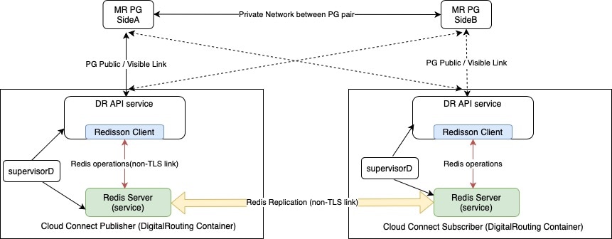
Double failure of the Digital Routing service:

The Digital Routing service works in an Active-Standby model for high availability. Whenthe Digital Routing service on the Cloud Connect restarts,the MR PG loses its connection to the service. The MR PG then attempts to connect to the Digital Routing service, which is running on the peer Cloud Connect node. If the service does not accept the connection request for whatever reason, it results in the double failure of the Digital Routing service.

If you are planning for a maintenance window for the active side of the Digital Routing service, ensure that the standby side is healthy, and can accept the connection request from MR PG.

When the MR PG connects back to the Digital Routing service that had restarted and which still doesn’t have any task context since the peer was not marked as Primary / Active, all task contexts including the tasks that were queued in the CCE router and waiting to be assigned to agents, as well as the tasks that were being handled by the agents before the double failure, are lost.

Data Flow for New Task Request During CCE Router Failure

The following diagram illustrates how the data flows for a new task request when there is a failure on both sides of the CCE router or when the MR PG loses connectivity with the CCE router:

Figure 23. Router Failure
  1. Webex Connect initiates a CCE Create Task API request towards the Digital Routing service through a load balancer or reverse proxy server. The Webex Connect Flow transaction ID ($flid) is converted into a universally unique identifier (UUID) and passed into the payload as client TaskID. The request also contains the script selector that would be sent to CCE along with any additional task context in the form of call variables and Expanded Call Context (ECC) variables. The Webex Engage ConversationID is also passed along as a special ECC variable called user_DR_MediaResourceID. This ECC variable is essential for the Agent Desktop to be able to load the conversation.

  2. The Digital Routing service acknowledges the API request with a response code "201 / Created".

  3. The Digital Routing service sends a webhook notification to indicate that the task with specified TaskID is created and is waiting to be sent to CCE for routing.

  4. The Digital Routing service creates a request, assigns a unique DialogueID to the request, includes the Script Selector and Task Context variables that are received from Webex Connect, and sends the request to the MR PIM.

  5. The Digital Routing service sends a webhook notification to indicate that the task with specified TaskID is created and is waiting to be sent to CCE for routing.

  6. The MR PIM forwards the request to the CCE router through the MR PG OPC, along with all the context that it received from the Digital Routing service.

  7. The MR PG loses connectivity with both sides of the CCE router because of a network issue.

  8. The MR PG OPC notices the connectivity loss and sends a message to the Digital Routing service through the MR PIM to prevent further route requests being sent to the PG.

  9. The MR PIM forwards the message to the Digital Routing service, and also starts cleaning up the tasks in the PG memory.

  10. The MR PIM also sends a message to the Digital Routing service for each task that was cleared from the PIM memory.

  11. After the router connectivity is restored from the MR PG, the PG sends a message to the Digital Routing service through the MR PIM to re-enable task routing.

  12. The MR PIM forwards the message to the Digital Routing service.

  13. The Digital Routing service keeps track of task queue positions and attempts to requeue tasks that were cleared due to a router failure in the same order in which the tasks were originally received.

  14. If the task cannot be injected back into MR PIM for a considerable number of times that is more than the maximum lifetime of the task (as defined in the Task Queue Settings in the Unified CCE Administration portal), then the task is automatically closed with a disposition code CD_MAX_DIALOG_LIFETIME_EXCEEDED.

  15. For such timed out tasks, the Webex Connect initiates the CLOSED webhook event that includes the disposition code, CD_MAX_DIALOG_LIFETIME_EXCEEDED.

Data Flow for New Task Request During MR PG Failure

The following diagram illustrates how the data flows for a new task request when there is a failure on MR PG:

Figure 24. MR PG Failure
  1. Webex Connect initiates a CCE Create Task API request towards the Digital Routing service through a load balancer or reverse proxy server. The Webex Connect Flow transaction ID ($flid) is converted into a universally unique identifier (UUID) and passed into the payload as client TaskID. The request also contains the script selector that would be sent to CCE along with any additional task context in the form of call variables and Expanded Call Context (ECC) variables. The Webex Engage ConversationID is also passed along as a special ECC variable called user_DR_MediaResourceID. This ECC variable is essential for the Agent Desktop to be able to load the conversation.

  2. The Digital Routing service acknowledges the API request with a response code "201 / Created".

  3. The Digital Routing service sends a webhook notification to indicate that the task with specified TaskID is created and is waiting to be sent to CCE for routing.

  4. The Digital Routing service creates a request, assigns a unique DialogueID to the request, includes the Script Selector and Task Context variables that are received from Webex Connect, and sends the request to the MR PIM.

  5. The Digital Routing service sends a webhook notification to indicate that the task with specified TaskID is created and is waiting to be sent to CCE for routing.

  6. The MR PIM forwards the request to the CCE router through the MR PG OPC, along with all the context that it received from the Digital Routing service.

  7. A failure occurs in the active side of the MR PG between the PIM and the Digital Routing service, while the task is in the CCE router queue.

  8. The Digital Routing service detects that the active side of MR PG has failed and waits for the stand-by side of the MR PG to establish connection with one of the Cloud Connect nodes. All task routing and messages towards the MR PG are temporarily disabled.

  9. After the Digital Routing service receives a message from the PIM, it acknowledges the connection request.

  10. On receipt of the message to resumes task routing, from the MR PIM, the Digital Routing service re-injects all the tasks that were in the Queued state back into CCE. From now on, the flow is identical to the new task request. The task gets routed to the agent and the Digital Routing service receives intimation of the agent that was assigned to the task by the CCE Router.