Prepare Customer Site Servers
Perform all the procedures in this section on the Side A and the Side B servers.
The documentation set for this product strives to use bias-free language. For the purposes of this documentation set, bias-free is defined as language that does not imply discrimination based on age, disability, gender, racial identity, ethnic identity, sexual orientation, socioeconomic status, and intersectionality. Exceptions may be present in the documentation due to language that is hardcoded in the user interfaces of the product software, language used based on RFP documentation, or language that is used by a referenced third-party product. Learn more about how Cisco is using Inclusive Language.
Perform all the procedures in this section on the Side A and the Side B servers.
Stripe size: 128KB
Read Policy: Read Ahead Always
Write Policy: Write Back with BBU
| Step 1 |
Power on the UCS server, making sure that Quiet Boot is disabled in BIOS. |
| Step 2 |
Press Ctrl-H during the initial startup sequence to enter the MegaRAID BIOS configuration utility. |
| Step 3 |
Click Start. |
| Step 4 |
Select Configuration Wizard on the left panel. Click New Configuration. Then click Next. |
| Step 5 |
At the prompt to clear the configuration, click Yes. |
| Step 6 |
Select Manual Configuration. Then click Next. |
| Step 7 |
On the next screen, in the left panel, add the first eight drives to create Drive Group0 as follows:
|
| Step 8 |
Add the remaining eight drives to create Drive Group1 as follows:
|
| Step 9 |
Add Drive Group0 to a span as follows:
|
| Step 10 |
Configure RAID for Drive Group0 as follows:
|
| Step 11 |
Click Back to add the second RAID 5 array as follows:
|
| Step 12 |
At the RAID Selection screen:
|
| Step 13 |
Click Yes at the BBU warning screen. |
| Step 14 |
Click Next at the Virtual Live Definition screen to indicate that you have finished defining virtual drives. |
| Step 15 |
Click Accept at the Configuration Preview screen to accept the RAID configuration. |
| Step 16 |
Click Yes to save the configuration. |
| Step 17 |
Click Yes to start drive configuration. |
| Step 18 |
Click Home to exit the Wizard when both drives report their status as Optimal. |
| Step 19 |
Click Exit. After RAID configuration is complete on the drives, the system may try to initialize (format) the new RAID array. In this event, the current initialization progress can be seen from the Web BIOS screen. Wait for the background initialization to complete before proceeding with any of the subsequent server configuration steps such as installing ESXi. You can check background initialization progress on either the Web BIOS Home screen or Virtual Drives screen. |
|
Using Cisco Integrated Management Controller, check that the following settings are configured correctly:
For more information regarding RAID configuration for C240 M4SX in Configure RAID with GUI (UCS C-Series M4 Servers) section, see Cisco Collaboration on Virtual Servers Guide at: https://www.cisco.com/c/en/us/td/docs/voice_ip_comm/cucm/virtual/CHCS_BK_C7C7ED05_00_cisco-collaboration-on-virtual-servers/CHCS_BK_C7C7ED05_00_cisco-collaboration-on-virtual-servers_chapter_01.html#CUCM_TK_C2DC4F2D_00. |
The disk array configuration for the UCS C240 M5SX is already set up to match the requirements. Verify the settings as follows:
|
Using Cisco Integrated Management Controller, check that the following settings are configured correctly:
For more information regarding RAID configuration for C240 M5SX, see the Installation and Configuration section of the Cisco Collaboration on Virtual Servers Guide at: |
Packaged CCE uses standard VMware vSphere ESXi installation procedures. For installation procedures to install the supported version of vSphere ESXi that you are installing, see the VMware documentation at https://www.vmware.com/support/pubs/.
For Packaged CCE, you must install the ESXi on the first drive as the default boot drive for the server. Packaged CCE has no unique requirements.
After installing vSphere ESXi, add the remaining datastores. Refer to the vSphere Storage Guide for the vSphere ESXi version in your deployment, available at https://www.vmware.com/support/pubs/.
Required datastores are dictated by the hardware platform used. Cisco UCS C-Series servers require a fixed and validated configuration.
Refer to the vCenter Server and Host Management documentation at https://www.vmware.com/support/pubs/
Customers without vCenter can install on management desktops to administer the Packaged CCE servers.
After you set up RAID configuration and add the datastores, run the RAID Config Validator utility to ensure that your datastore configuration is correct.
To run the utility, Java 7 (any update) must be installed. Java 8 and later releases are not supported.
| Step 1 |
Download the Packaged CCE RAID Config Validator utility from the at https://software.cisco.com/download/type.html?mdfid=284360381&i=rm. Extract the zip file locally. |
| Step 2 |
Open the Windows command prompt and change to the directory where you downloaded the file. |
| Step 3 |
Enter this command to run the tool: java -jar PackagedCCEraidConfigValidator-<version>.jar <IP Address of the Side A ESXi host> <username> <password> Messages appear on the monitor to show that the validation is starting. You then see an indication of a valid or invalid configuration. |
| Step 4 |
If your configuration is valid, repeat step 2. Enter the IP address of the Side B server instead of the Side A server. |
If the utility reports an invalid configuration, you must recreate the RAID configuration. To do this, reset the RAID configuration, re-install ESXi, and then re-run the RAID Config Validator utility to re-validate the configuration.
RAID configuration errors include:
Before you complete the configuration steps in this section, the customer site UCS B-Series must be installed, configured, and operational.
For additional information and guidance on UCS B-Series installation and configuration, refer to the UCS B-Series documentation (https://www.cisco.com/c/en/us/products/servers-unified-computing/product-listing.html) or your Cisco Data Center Unified Computing Authorized Technology Provider.
This section includes only specific configuration requirements for Packaged CCE deployments on the UCS B-Series platform. Customers may have varying design and configuration needs due to their data center requirements and infrastructure. However, all configurations must meet the Packaged CCE requirements for high availability. For example, the design must not create the potential for a single point of failure, which can adversely impact the operation of Cisco call processing applications.
UCS B-Series may have a variable number of LUNs on the SAN provisioned to meet Packaged CCE IOPS requirements.
See the Virtualization for Cisco Packaged CCE at https://www.cisco.com/c/en/us/td/docs/voice_ip_comm/uc_system/virtualization/pcce_virt_index.html for IOPs requirements.
 Note |
All UCS hardware configuration examples in this section use the Cisco UCS Manager GUI. You can also use the UCS Manager CLI or API. |
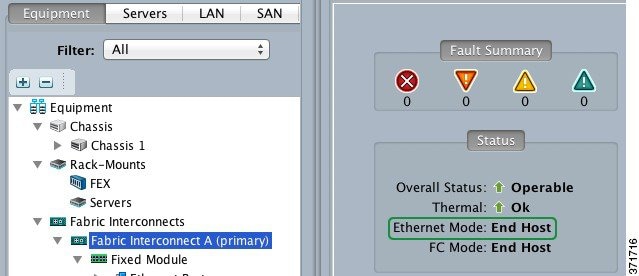
The Fabric Interconnects' Ethernet Mode must be set to End Host.
Cisco UCS Fabric Interconnect Ethernet uplinks (Uplink Ports) for Packaged CCE are required to be 10G, with each Fabric Interconnect cross-connected to two common-L2 data center switches. The uplinks can be in a single-link, Port-Channel (EtherChannel), vPC or VSS (MEC) uplink topology.
If any Port-Channel uplink are used, corresponding Port-Channel must be created in UCS Manager, where the ID of the Port-Channel matches that on the data center switch.
If Port-Channel uplinks to data center switches are used, the UCS B Series Fabric Interconnects support only Link Aggregation Control Protocol (LACP). Ensure that the data center switch and Port-Channels are configured for, and support, LACP. This requirement also applies to vPC and VSS Port-Channels.
Both End Host and Switching modes are supported. End Host is the default for FC and FCoE NPIV with a supported FC Switch. Switching mode requires FC Zoning to be configured in the Fabric Interconnects. Refer to UCS Fabric Interconnect documentation for more information on these modes and use cases, and to specific SAN switch and SAN controllers vendor documentation as necessary. UCS Fabric Interconnect documentation is available at https://www.cisco.com/c/en/us/products/servers-unified-computing/ucs-6200-series-fabric-interconnects/index.html.
Packaged CCE supports all FC and FCoE connected SAN topologies as supported by the UCS Fabric Interconnects, provided that all storage redundancy, latency, IO and bandwidth requirements are met.
Note |
If direct-attach SAN is used, qualified direct-attach FC and FCoE storage vendors are currently limited to EMC, Hitachi Data Systems, and NetApp. Please refer to the latest Cisco UCS hardware compatibility list for the most current qualified vendors and models, at https://www.cisco.com/en/US/products/ps10477/prod_technical_reference_list.html. |
Unified CM and CCE applications set L3 QoS DSCP (AF/CS), which is not handled by the Fabric Interconnects; Fabric Interconnects are not L3 aware. Packaged CCE does not require specific QoS System Class or QoS Policy settings for VMware vSwitches.
Cisco UCS Manager uses Pools, Policies and Templates which are collected in a Service Profiles Template and applied to a blade as a Service Profile.
Packaged CCE does not have any specific requirements for the blade Service Profile or Service Profile Templates, other than the vNIC and vHBA requirements to conforming to network VLAN and FC/FCoE VSAN requirements (see vNIC Requirements and vHBA Requirements).
For consistent and verifiable configuration and conformance of server configurations, use vNIC, vHBA and Service Profile Templates.
For more detail on UCS blade configuration and service profiles and templates, refer to the appropriate Cisco UCS Manager documentation.
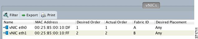
Packaged CCE requires that you configure a minimum of two vNIC Ethernet interfaces on the UCS B-series blade. You must assign each of these two interfaces to alternate Fabric Interconnects for redundancy.
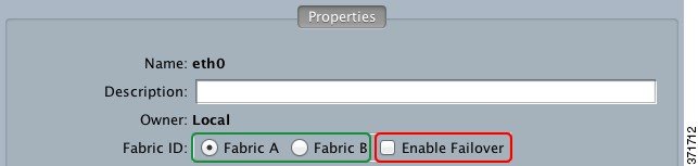
Do not enable Fabric Failover for any Packaged CCE host vNIC interfaces.
The VMware VMKernel and Management interface is allowed to share the same vNICs with Packaged CCE.
This table is an example of collapsed vNIC interfaces for all VLANs:
| vNIC | VLANS | Fabric | Notes |
|---|---|---|---|
|
eth0 |
PCCE Visible (Active) PCCE Private (Standby) VMware Kernel & Management (Active) Default VLAN (Active) Other Management (Active) |
A |
Active and Standby are denoted to show the reference design for traffic flow through these vNICs as aligned to Fabric Interconnects as controlled in the VMware layer. See the UCS B Series Networking section for more details. |
|
eth1 |
PCCE Visible (Standby) PCCE Private (Active) VMware Kernel & Management (Standby) Default VLAN (Standby) Other Management (Standby) |
B |
Note |
Networks other than the Packaged CCE Visible and Private networks are not required to be set to Active/Standby, as shown in the table. They can be set to Active/Active (no override), or assigned as needed to distribute load evenly across the infrastructure. |
You must configure a minimum of two vHBA FC interfaces on the UCS B-series blade. You must assign each of these two interfaces to alternate Fabric Interconnects for redundancy.
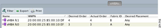
These FC vHBAs can be used for either FC or FCoE connected SAN. Use a different VSAN for each Fabric Interconnect (A/B) path to the SAN, but common VSAN is also supported.
Common (as depicted) or separate vHBA interfaces may be used for Packaged CCE datastores and ESXi Boot from SAN storage path.
This tool performs checks on currently deployed UCS B-Series Fabric Interconnect clusters to determine compliance with Packaged CCE requirements. If Packaged CCE will be deployed on two separate UCS B Series Fabric Interconnect clusters, run the tool for each cluster.
Note |
To run this tool, the Java version applicable to the version of the tool you are using must be installed. |
Java 7 (any update) or Java 8 (any update) must be installed.
In addition to running this tool, see Virtualization for Cisco Packaged CCE at https://www.cisco.com/c/en/us/td/docs/voice_ip_comm/uc_system/virtualization/pcce_virt_index.html and the Solution Design Guide for Cisco Packaged Contact Center Enterprise at https://www.cisco.com/c/en/us/support/customer-collaboration/packaged-contact-center-enterprise/products-technical-reference-list.html to ensure full compliance.
To begin, download this file:
UCSValidatorTool-<version>.zipWhere <version> indicates the version of the tool you intend to install.
Once downloaded, follow these instructions to run the tool:
Unzip the UCSValidatorTool zip file to create a UCSValidatorTool directory.
Change to the UCSValidatorTool directory.
Run "java -jar UCSValidatorTool.jar".
The tool requests the following information:
Company name (Required to generate the PDF filename using Company Name)
IP Address of UCS Manager
HTTPS (yes/no)
Port (defaults to 80 for HTTP/443 for HTTPS)
Username: Read-only credentials to UCS Manager
Password
The following shows an example of the prompts.
Welcome to the Unified Computing System Verification Utility (version 11.6.1.0).
This tool will validate the UCS Fabric Interconnects for Packaged CCE requirements.
Enter company name: Cisco Systems Inc.
Enter UCS Manager cluster IP address: <ip-address-of-UCS-manager>
Use HTTPS? Yes/No: > (n[o]=80; y[es]=443)y
Port: [443]<port-number>
Enter UCS Manager access information with read privilege:
Username: <your-username>
Password: ****
Processing ........
After the validation process is complete, a summary of the pass/fail test results is displayed on the console, and output as both a log file (results/ucsValidation.log) and as a PDF file (Company-Name-date.pdf).
The following table provides a detailed explanation of each tool validation rule check run against the UCS B-Series Fabric Interconnects.
|
Category |
Type |
Requirements |
|---|---|---|
|
Fabric Interconnect |
Count |
Two matching Fabric Interconnects (HA) |
|
Ethernet Mode |
Mode must be End Host |
|
|
UCS Manager |
Version 2.2(1) or later. A higher version than this may be required depending on the version of ESXi that you installed. Use the UCS Hardware and Software Compatibility tool to help you select the appropriate version. The tool can be found here: |
|
|
Ethernet Uplinks |
The Fabric Interconnect rule: Checks all Ethernet uplinks for one set that passes the following requirement validation rules.
Caveats:
|
|
|
IO Model (Fabric Extender) |
Count |
The IO Model (Fabric Extender) rule:
Caveats:
|
|
SAN Hardware and Transport |
Type and Data Rate |
The SAN Hardware and Transport rule: Checks all FC uplink types for one set of FC uplinks that pass the following requirement validation rules.
Caveats:
|
The following table provides a detailed explanation of the UCS B-Series requirements not validated by this tool.
|
Category |
Requirement |
|---|---|
|
UCS Blade Server |
UCS blade specification must match one of the following:
Note: B200 M4 TRC#1 is supported for Release 11.0(1) and later only. Storage and Ethernet interface requirements:
|
|
UCS SAN HCL |
The following SAN components (as applicable) must be on the UCS HCL for the version of UCS Manager firmware used:
|
|
SAN LUN |
SAN LUNs must:
|
|
VMware vSphere ESXi |
The tool does not connect to or check any vSphere ESXi specific requirements. |
For more UCS HCL resources, see:
Packaged CCE requires that all parts of the solution have the same time. While time drift occurs naturally, it is critical to configure NTP to keep solution components synchronized.
To prevent time drifts on Live Data reports, the NTP settings on the Rogger VMs, the PG VMs, the AW VMs, and on the Cisco Unified Intelligence Center Publisher and Subscriber VMs must be synchronized.
For Cisco UCS B-series servers, you also must set the time zone and NTP Time Server using the UCS Manager. See Set Time Zone and NTP Time Server for Cisco UCS B-Series Servers for more information.
Important |
Microsoft periodically releases cumulative time zone updates. These updates include worldwide changes to time zone names, bias (the amount of time in minutes that a time zone is offset from Coordinated Universal Time (UTC)), and observance of daylight saving time. These patches update the information in the Windows registry. When these updates are available, apply them to all virtual machines in the deployment that are running a Microsoft Windows operating system. |
The Windows Active Directory Primary Domain Controller (PDC) emulator master for the forest in which the Packaged CCE domain resides (whether same, parent, or peer) must be properly configured to use an external time source. This external time source should be a trusted and reliable NTP provider, and if already configured for the customer's forest, must be used (and useable) as same source for all other applications as detailed in this section for the Packaged CCE solution.
How to configure an authoritative time server in Windows Server.
Note |
Do not use the "Fix it for me" function in this article. |
Microsoft Windows Server Domains do not automatically recover or fail over the authoritative internal time source for the domain when the PDC emulator master server is lost, due to hardware failure or otherwise. This article, Time Service Configuration on the DCwith PDC Emulator FSMO Role, helps describe how you must additionally configure the new target server to be the authoritative internal time source for the domain. It also covers manual intervention to recover and seize or reassign the PDC Flexible Single-Master Operations (FSMO) role to another domain controller.
Windows hosts in the domain are automatically configured to synch their time with a PDC emulator, whether by the PDC emulator master with authoritative internal time source or chained from same in the domain forest hierarchy.
Note |
Replace peers with a comma-separated list of NTP servers. |
Restart the w32time service: net stop w32time && net start w32time.
Synch w32time service with peers: w32tm /resync.
Use the following Service Control command to ensure proper start of the w32time service on any reboot of the server: sc triggerinfo w32time start/networkon stop/networkoff.
Cisco IOS Voice Gateways must be configured to use the same NTP source for the solution in order to provide accurate time for logging and debugging. See Basic System Management Configuration Guide, Cisco IOS Release 15M&T: Setting Time and Calendar Services.
Components such as Unified Intelligence Center, Finesse, Social Miner , and Unified Communications Manager must point to the same NTP servers as the domain authoritative internal time source.
CLI commands for NTP Servers
To list
existing ntp servers:
utils
                                          				  ntp servers list
To add an
additional ntp server:
utils
                                          				  ntp server add <host or ip address to add>
To delete an
existing ntp server:
utils
                                          				  ntp server delete (row number of the item to delete)
. Press
Enter.
All Packaged CCE ESXi hosts (including those for optional components), must point to the same NTP server(s) used by the Windows domain PDC emulator master as the their external time source.
For details on configuring NTP on ESXi hosts, see the VMware documentation athttps://www.vmware.com/support/pubs/ .
Set the time zone and NTP Time server for UCS B-series server in the UCS Manager.
| Step 1 |
From the Admin tab in UCS Manager, select . |
| Step 2 |
Select the Time Zone from the down-down menu. |
| Step 3 |
Click Add NTP Time Server. |
| Step 4 |
Enter the IP address of the NTP Time Server, and click OK. |
| Step 5 |
Click Save. |
Packaged CCE uses the Global Catalog for Active Directory Lookup. All domains in the AD Forest in which the Packaged CCE Hosts reside must publish the Global Catalog for that domain. This includes all domains with which your solution interacts, for example, Authentication, user lookup, and group lookup.
In a multi-domain forest, a Global Catalog is required at each AD site. Global Catalog is a central repository of domain information in an AD forest. A significant performance degradations and failure occur without local or Global Catalog. It is important for every AD query to search each domain in the forest. The multi-site deployments are required to query across WAN links.
Note |
This does not imply cross-forest operation. Cross-forest operation is not supported. |
 Feedback