- Preface
- Cisco Unified Contact Center Solutions
- Unified CCE Reference Designs
- Contact Center Enterprise Solutions Overview
- Configuration Limits and Feature Availability for Reference Designs
- Packaged Contact Center Enterprise Solution Design Considerations
- High Availability and Network Design
- Design Considerations for Integrated Features
- Bandwidth, Latency, and QoS Considerations
- Sizing and Operating Conditions for Reference Designs
- Avaya and ICM-to-ICM Gateway Support
- Solution Security
- Contact Center Solutions Architecture
- Core Components
- Optional Cisco Components
- Third-Party Components
- Integrated Features
- Call Flows
- Topologies
- Solution Administration
- Solution Serviceability and Monitoring
- Localization
Contact Center Solutions Architecture
 Note | The first four chapters of this book are for anyone who wants to get familiar with the contact center enterprise solutions:
|
- Packaged CCE Solution Architecture
- Cisco HCS for Contact Center Solution Architecture
- Unified CCE Solution Architecture
Packaged CCE Solution Architecture
Packaged CCE is a predesigned, bounded deployment model of Unified CCE. The core components are deployed as on-box Virtual Machines (VMs) that are described by OVA files downloaded from https://www.cisco.com.
The Packaged CCE VMs provide the essential set of contact center functionality—call and non-voice task processing, prompts and rich VXML scripting, voice response collection, agent selection, queuing, and reporting. With its controlled environment and well-defined configuration and deployment boundaries, Packaged CCE is a robust solution with high availability and solution serviceability. Additional benefits are simplified ordering and deployment rollout, easier operation and maintenance, and Unified CCE Administration—a streamlined, browser-based administration interface for configuring the system and monitoring its health.
Cisco HCS for Contact Center Solution Architecture
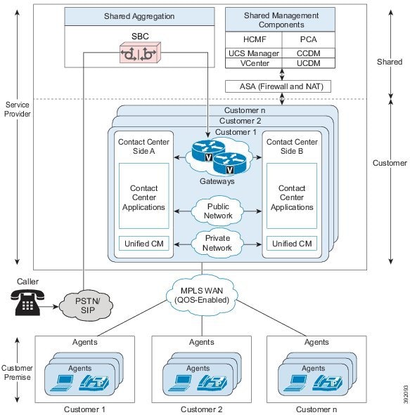
Cisco HCS for Contact Center delivers in a hosted environment almost all of the components and features as a Unified CCE solution. Cisco HCS for Contact Center supports a subset of the Unified CCE models. You, as the service provider, manage the maintenance of the hosted environment. For your customers, this means lower hardware costs, easier and faster deployment, and no need to worry about upgrades, maintenance staff, and unpredictable costs.
Cisco HCS for Contact Center has an aggregation layer and a shared management layer. It combines Cisco Hosted Collaboration Solution components with the multiple network connections and route requests to the dedicated customer instances. The shared aggregation consists of a Hosted Collaboration Solution SBC for interfacing to a PSTN. The shared management consists of UCDM, Unified CCDM, HCM-F, Cisco Prime Collaboration Assurance (PCA), Cisco UCS Manager, VMware vCenter, and Cisco ASA (Firewall/NAT).
Figure 1. Cisco HCS for Contact Center
Unified CCE Solution Architecture
Cisco Unified Contact Center Enterprise (Unified CCE) is a solution that delivers intelligent call routing, network-to-desktop Computer Telephony Integration (CTI), and multichannel contact management to contact center agents over an IP network. Unified CCE combines software IP automatic call distribution (ACD) functionality with Cisco Unified Communications to enable companies to deploy an advanced, distributed contact center infrastructure rapidly.
This design guide describes the deployment models and their implications including scalability, fault tolerance, and interaction between the solution components.
The Unified CCE product integrates with Cisco Unified Communications Manager, Cisco Unified Customer Voice Portal, Cisco VoIP Gateways, and Cisco Unified IP Phones. Together these products provide contact center solutions to achieve intelligent call routing, multichannel ACD functionality, voice response unit (VRU) functionality, network call queuing, and consolidated enterprise-wide reporting. Unified CCE can optionally integrate with Cisco Unified Intelligent Contact Manager to network with legacy ACD systems while providing a smooth migration path to a converged communications platform.
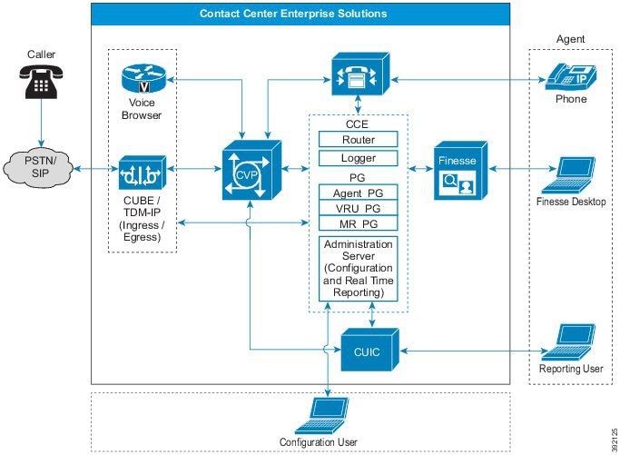
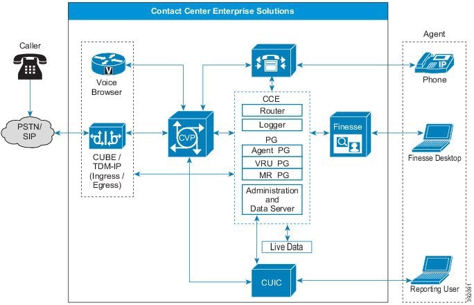
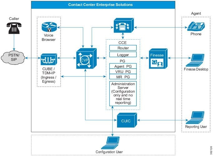
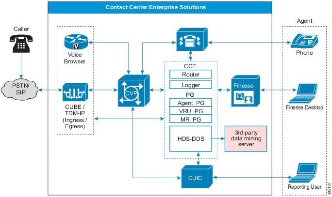
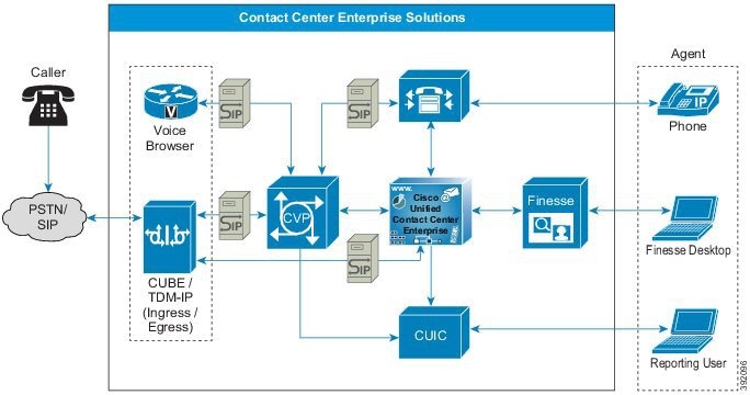
The Unified CCE solution is designed for implementation in both single and multisite contact centers. Unified CCE uses your existing IP network to lower administrative expenses and to include branch offices, home agents, and knowledge workers in your contact center. The following figure illustrates a typical Unified CCE setup.
Figure 2. Typical Unified CCE Solution Deployment

The Unified CCE solution consists primarily of four Cisco software products:
Unified Communications infrastructure—Cisco Unified Communications Manager
Queuing and self-service—Cisco Unified Customer Voice Portal (Unified CVP)
Contact center routing and agent management—Unified CCE. The major components are CallRouter, Logger, Peripheral Gateway, and the Administration & Data Server/Administration Client.
Agent desktop software—Cisco Finesse
The solution is built on the Cisco IP Telephony infrastructure, which includes:
Cisco Unified IP Phones
Cisco Voice Gateways
Cisco LAN/WAN infrastructure
Core Components
Requests coming into a contact center enterprise solution usually interact with the core components in the following order:
Cisco Ingress, Egress, and VXML Gateways
Cisco Unified Customer Voice Portal
Cisco Unified Contact Center Enterprise
Cisco Virtualized Voice Browser
Cisco Unified Communications Manager
Cisco Finesse
Cisco Unified Intelligence Center
- Ingress, Egress, and VXML Gateways
- Cisco Unified Customer Voice Portal
- Contact Center Enterprise
- Cisco Virtualized Voice Browser
- Cisco Unified Communications Manager
- Cisco Finesse
- Cisco Unified Intelligence Center
Ingress, Egress, and VXML Gateways
You can use these gateways in your solution:
Cisco Voice TDM gateway
Cisco Unified Border Element
Cisco VXML gateway
Figure 3. Ingress, Egress, and VXML Gateways
 Note | Voice Browser refers to either VXML Gateways or Cisco Virtualized Voice Browser (VVB). |
TDM gateways and CUBE gateways can act as both ingress (for inbound calls) and egress gateway (for outbound calls) in a specific deployment.
These types of gateways can be colocated or exist on separate physical gateways.
Cisco IOS-XE does not support VXML gateway functionality.
Cisco TDM Voice Gateway
The Cisco Ingress Voice Gateway is the point at which an incoming call enters the contact center enterprise solution. It terminates time division multiplexing (TDM) calls on one side and implements VoIP on the other side. It serves as a pivot point for the extension of calls from the TDM environment to VoIP endpoints. This conserves WAN bandwidth because no hairpinning of the media stream occurs. The Cisco Ingress Voice Gateway also provides for call switching capabilities at the command of other contact center enterprise solution components.
You can use the Ingress Voice Gateway for the PSTN Voice Gateway. The Ingress Voice Gateway converts TDM speech to IP and converts DTMF digits to RFC2833 events.
| Note | Unified CVP does not support passing SIP-Notify DTMF events. |
You can separate the VXML functionality from the Ingress Voice Gateway to provide a separate PSTN ingress layer. The separate PSTN layer and VXML enable the deployment to support many VXML sessions and PSTN interfaces. An ingress gateway that handles numerous ingress calls cannot also support that many VXML sessions. In such cases, you can off-load the VXML sessions to a separate farm of Voice Browsers, such as Cisco VVB.
| Note | You can use any TDM interface that your Cisco IOS gateway, IOS version, and the contact center enterprise components all support. |
The Cisco Egress Voice Gateway is used only when calls are extended to TDM networks or equipment. For example, transferring a call to a PSTN or a TDM automatic call distributor (ACD). While the Real-time Transport Protocol (RTP) stream runs between the gateway ports, the signaling stream logically goes through the Unified CVP Server and Cisco Unified CCE. This allows subsequent call control (such as transfers).
Both TDM Ingress Gateways and Egress Gateways support Session Initiation Protocol (SIP).
Cisco Unified Border Element
The Cisco Unified Border Element (CUBE) is a Cisco router that runs as a Session Border Controller (SBC). SBCs interconnect independent Voice over IP (VoIP) and video over IP enterprise networks for data, voice, and video transport. SBCs are critical components for scaling networks from VoIP islands within a single customer network to an end-to-end IP community. SBCs are used both inside an enterprise and to communicate beyond an enterprise across service provider networks.
| Note | When this guide refers to CUBE, we always mean the Enterprise version, not the Service Provider version. |
CUBE runs on Cisco Integrated Services Router (ISR) and Aggregation Service Router (ASR) routers. The Cisco Cloud Services Router (CSR) can run a virtual CUBE.
CUBE adds the following features to the Cisco IOS and IOS XE software image:
A Network-to-Network Interface point for billing, security, call admission control, quality of service, and signaling interworking
The feature set necessary to support the transition to SIP trunking
The capability to act as a distinct demarcation point between two networks.
The capability to intelligently allow or disallow real-time traffic between networks.
The use of third-party SIP trunks with contact center enterprise solutions is supported by using CUBE. CUBE performs the role of session border controller for SIP normalization and interoperability.
Virtual CUBE for Contact Center Solutions
In compatible Cisco IOS XE releases, Contact Center Enterprise (CCE) solutions support CUBE as a virtualized form factor. You can install virtual CUBE (vCUBE) on VMware ESXi hypervisors. CCE supports vCUBE in the following configurations:
Number of vCPUs | Memory Reservation | Concurrent WebSocket Forking Sessions |
|---|---|---|
1 | 4 GB RAM | 500 |
2 | 4 GB RAM | 600 |
4 | 8 GB RAM | 1000 |
For more details on CUBE sizing, see the Licensing Options section in the Cisco Unified Border Element Version 14 Data Sheet at https://www.cisco.com/c/en/us/products/collateral/unified-communications/unified-border-element/data-sheet-c78-729692.html
vCUBE supports most of the features available in CUBE. It supports Outbound Option without CPA. Features that manage the media plane do not work in the Cisco Cloud Services Router (CSR) router. vCUBE does not support the following Digital Signal Processor (DSP) features:
Audio and Video Codec Transcoding or Transrating
DTMF interworking
Call Progress Analysis (CPA)
Noise Reduction (NR), Acoustic Shock Protection (ASP), and Audio Gain
IOS-based hardware MTP
A mix of G.729 and G.711 during conferencing
DSP high availability
High availability protected mode (instances on the same host)
| Note | You can use multicodec, software conferencing, and MTP that are controlled by Unified CM instead of the DSP available in physical CUBEs. You can add a dedicated physical gateway if your solution requires CPA or mixed codecs for conferencing. |
Limited support for Voice Class Codec (VCC). The codec supported on peer leg is included in offer. Other codecs are filtered out.
For more details on support for vCUBE, see the vCUBE section in the Cisco Unified Border Element Configuration Guide at http://www.cisco.com/c/en/us/support/routers/cloud-services-router-1000v-series/products-installation-and-configuration-guides-list.html and the Compatibility Matrix for your solution at https://www.cisco.com/c/en/us/support/customer-collaboration/unified-contact-center-enterprise/products-device-support-tables-list.html .
Cisco VXML Gateway
Centralized deployment models often include VXML Gateways. The VXML Gateway interprets VXML pages from the VXML Server.
| Note | The term Voice Browser can mean either a VXML Gateway or Cisco Virtualized Voice Browser (Cisco VVB). |
You can cache audio prompts from a third-party media server in a VXML Gateway to reduce WAN bandwidth and prevent poor voice quality. The VXML document provides either a pointer to the location of the audio file or the address of a text-to-speech (TTS) Server to stream the audio. The VXML Gateway interacts with automatic speech recognition (ASR) and TTS Servers through Media Resource Control Protocol (MRCP).
You can deploy a Cisco IOS VXML Gateway on the same router as you deploy a Unified CVP Ingress Voice Gateway. This model is suitable for deployments with small branch offices. The Cisco IOS VXML Gateway can also run on a separate router platform. This model is suitable for deployments with large or multiple voice gateways, where only a small percentage of the traffic is for Unified CCE. This model allows shared public switched telephone network (PSTN) trunks between office users and contact center agents, and call routing based on the dialed number. VXML Gateway can store audio files on flash memory or on a third-party media server.
Unless a Cisco IOS VXML Gateway is combined with an Ingress Voice Gateway, the Cisco IOS VXML Gateway does not require TDM hardware. It interacts with VoIP on one side, and HTTP (carrying VXML or .wav files) and MRCP (carrying ASR and TTS traffic) on the other. As with Ingress Voice Gateways, Cisco IOS VXML Gateways are often deployed in farms for Centralized deployment models, or one in each office in Branch deployments.
As an alternative, you can deploy Cisco VVB on a separate virtual machine. This model is suitable for both standalone and comprehensive deployments. Cisco VVB communicates with ASR/TTS using MRCP.
| Note | Cisco IOS-XE does not have built-in voice browser capability. Therefore, deploying an IOS-XE ingress gateway with Unified CVP requires the use of a separate ISR G2 gateway or Cisco VVB to provide the voice browser. |
Cisco Unified Customer Voice Portal
Cisco Unified Customer Voice Portal combines open-standards support for speech with intelligent application development and industry-best call control.
Unified Customer Voice Portal (Unified CVP) is a software application that runs on Cisco Unified Computing System (UCS) hardware or specification-based equivalents. Unified CVP provides prompting, collecting, queuing, and call control services using standard web-based technologies. Its architecture is distributed, fault tolerant, and highly scalable. With CVP, voice terminates on Cisco Voice Browsers that interact with the Unified CVP application server using HTTP(S) (speech) and SIP (call control). Unified CVP includes the following subcomponents:
CVP Call Server
CVP VXML Server
CVP Media Server
CVP Reporting Server
Figure 4. Unified CVP in a Contact Center Enterprise Solution
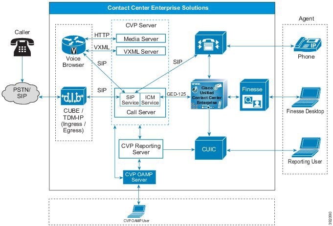
The Unified CVP software tightly integrates with the Unified CCE software for application control. Unified CVP interacts with Unified CCE using the Voice Response Unit (VRU) Peripheral Gateway Interface. The Unified CCE scripting environment controls the initiation of building-block functions such as play media, play data, menu, and collect information. The Unified CCE script can invoke external VXML applications to be run by the CVP VXML Server.
The CVP Call Studio is an Eclipse-based IDE for developing VRU applications. The VXML Server is the application server which hosts those VRU applications. The VXML Server handles sophisticated, high-volume VRU applications. It can also interact with custom or third-party J2EE-based services. You can achieve load balancing with an optional CUSP server or the built-in SIP Server Group in CVP.
Unified CVP can support multiple grammars for prerecorded announcements in several languages. CVP can optionally provide automatic speech recognition and text-to-speech capability. CVP can also access customer databases and applications through the Unified CCE software.
Unified CVP also provides a queuing platform for the Unified CCE solution. Voice and video calls can remain queued on CVP until they are routed to a contact center agent (or external system). The system can play back music or videos while the caller is on hold. When Unified CCE routes the call to an agent, the agent can send videos to a caller from the agent desktop application.
CVP Call Server
The Call Server component provides the following independent services, which all run on the same Windows server:
SIP service—This service communicates with the contact center enterprise solution components such as the SIP Proxy Server, Ingress Gateway, Unified CM SIP trunks, and SIP phones. The SIP service implements a Back-to-Back User Agent (B2BUA). This B2BUA accepts SIP invites from ingress voice gateways and typically directs those calls to an available Voice Browser port. After completing call setup, the Unified CVP B2BUA acts as an active intermediary for any subsequent call control. While the Unified CVP SIP signaling is routed through this service, this service does not touch the RTP traffic. Integrated into this B2BUA is the ability to interact with the Unified CCE through the ICM Service. This integration provides the ability for the SIP Service to query the Unified CCE for routing instruction and service control. This integration also allows Unified CCE to begin subsequent call control to do things such as transfers.
ICM service—This service is responsible for all communication between Unified CVP components and Unified CCE. It sends and receives messages on behalf of the SIP Service and the IVR Service.
| Note | The IVR service is now part of the VXML Server. |
CVP VXML Server
The VXML Server runs advanced VRU applications by exchanging VXML pages with the Voice Browser. Like almost all other Unified CVP product components, it runs within a Java 2 Enterprise Edition (J2EE) application server environment. Many customers add their own custom-built J2EE components to interact with back-end hosts and services. The VXML Server applications are written using Cisco Unified Call Studio and are deployed to the VXML Server for initiation of tasks. The applications are invoked on an as needed basis by a special Micro application which must be run from within the Unified CCE routing script.
The VXML Server can also be deployed in a standalone configuration that does not include any Unified CCE components. Applications are invoked as a direct result of calls arriving in the Voice Browser, and a single post application transfer is allowed.
| Note | The IVR service is now part of the VXML Server. So, it now uses a VXML server port license to run microapplication. In previous releases, the IVR service was part of the Call Server. |
The IVR service creates VXML pages that implement the Unified CVP Micro-applications based on Run External Script instructions received from Unified CCE. The IVR Service functions as the VRU leg (in Unified CCE terminology). You transfer calls to it from the SIP Service to run Micro-applications. The VXML pages that this module creates are sent to the Voice Browser. The IVR service is also responsible for the conversion of Unified CVP Micro-applications to VXML pages, and the reverse.
CVP Media Server
The Media Server component is simply a web server which provides prerecorded audio files, external VXML documents, or external Automatic Speech Recognition (ASR) grammars to the gateway. Some of these files can be stored in local flash memory on the gateways. However, in practice, most installations use a centralized media server to simplify distribution of prerecorded customer prompt updates. Media Server functionality can also include a caching engine. The gateways themselves, however, can also do prompt caching when configured for caching.
| Note | The Media Server component in Unified CVP is installed by default, along with Unified CVP Call Server and Unified CVP VXML Server. Media Servers can be deployed as a simplex operation, as a redundant pair, or with supported load balancers in a farm. The Voice Browser caches.wav files it retrieves from the Media Server. In most deployments, the Media Server encounters low traffic from Unified CVP. |
CVP Reporting Server
The Unified CVP Reporting Server provides consolidated historical reporting for a distributed self-service deployment. The CVP Reporting server is optional, unless your solution requires it for Courtesy Callback, trunk group reporting, and VRU reporting.
The CVP Reporting Server runs on a Windows server that hosts an IBM Informix Dynamic Server (IDS) database management system. The database schema is preset, but you can develop custom reports through Unified Intelligence Center and other reporting solutions.
The Reporting Server should be local to the Call Servers and VXML Servers. Deploying the Reporting Server at a remote location across the WAN is supported if the latency is less than 80ms RTT between the CVP Reporting Server and the CVP Call Server that it serves for VXML reporting traffic. This assumes the WAN bandwidth is not a constraint. If you have Remote Site deployment with local CVP Call Server, then you need to have local CVP reporting server at the Remote Site. However, between Remote Sites, you can have the CVP reporting server across WAN serving the CVP Call Server at the other Remote Site if the latency between the Remote Sites is less than 80 ms RTT.
The Reporting Server receives reporting data from the SIP Service (if used), and the IVR Service of the VXML Server. The Reporting Server depends on the Call Server to receive call records.
The Reporting Server does not perform database administrative and maintenance activities, such as backups or purging.
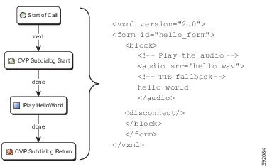
CVP Call Studio
Cisco Unified Call Studio is the service creation environment (script editor) for Unified CVP VXML Server applications. It is based on the open source Eclipse framework, which provides an advanced drag-and-drop graphical editing feature. Call Studio also provides options to insert vendor-supplied and custom-developed plug-ins that enable applications to interact with other services in the network. Call Studio basically is an offline tool. The only interaction with the Unified CVP VXML Server is to deliver compiled applications and plugged-in components to be run.
Call Studio provides an environment where you concentrate on your business logic. The tool handles the details of turning the logic into XML.
Figure 5. Call Studio Generates the Code for You
The Call Studio license is associated with the MAC address of the machine on which it is running. You typically designate one or more servers for that purpose. Cisco Unified Call Studio runs on a virtual machine or a Windows PC.
CVP Infrastructure
Unified CVP infrastructure includes the Web Services Manager, a services layer that supports a Diagnostic Portal API.
Unified CVP Infrastructure supports the following features:
Diagnostic Portal API service support by the Web Services Manager.
Unified System Command Line Interface (CLI) which is a client tool that supports the diagnostic portal API and other APIs for collecting diagnostic data.
Licensing:
Common Licensing for all CVP components that support FlexLM.
Licenses are only valid if the license feature,
CVP_SOFTWARE, is added. This feature is used to ensure if you are authorized to run the current version of CVP.
Serviceability Across Products with enhanced Log and Trace messages.
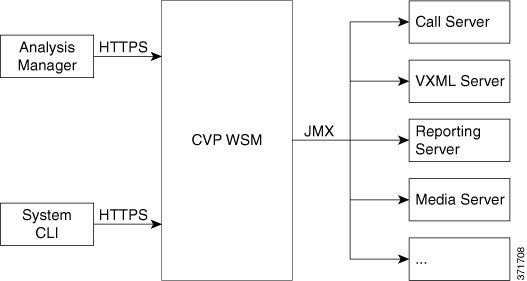
The CVP WebServices Manager (WSM) is a component that is installed automatically on all Unified CVP Servers, including Remote Operations Manager (ROM)-only installations. WSM interacts with various subsystems and infrastructure handlers, consolidates the response, and publishes an XML response. WSM supports secure authentication and data encryption on each of the interfaces.
The following figure shows how the two interfaces interact with the Web Services Management (WSM) to provide information about Unified CVP components.
Contact Center Enterprise
Unified Contact Center Enterprise (Unified CCE) provides these contact center features:
Agent state management
Agent selection
Call and task routing and queue control
VRU interface
CTI Desktop screen pops
Contact center reporting data
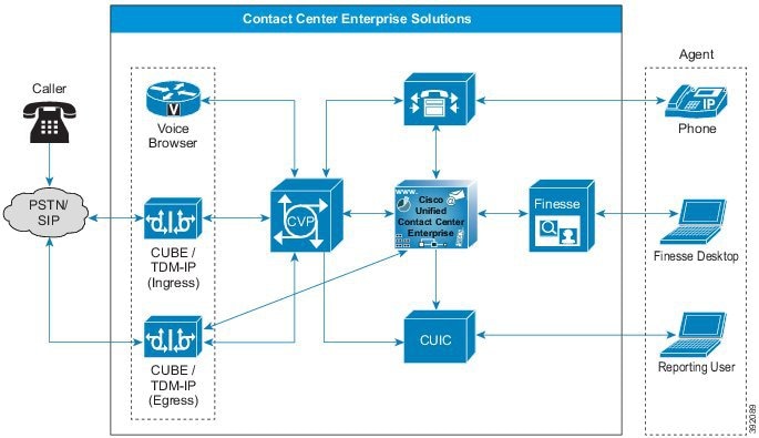
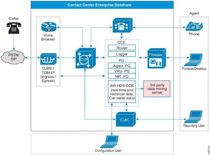
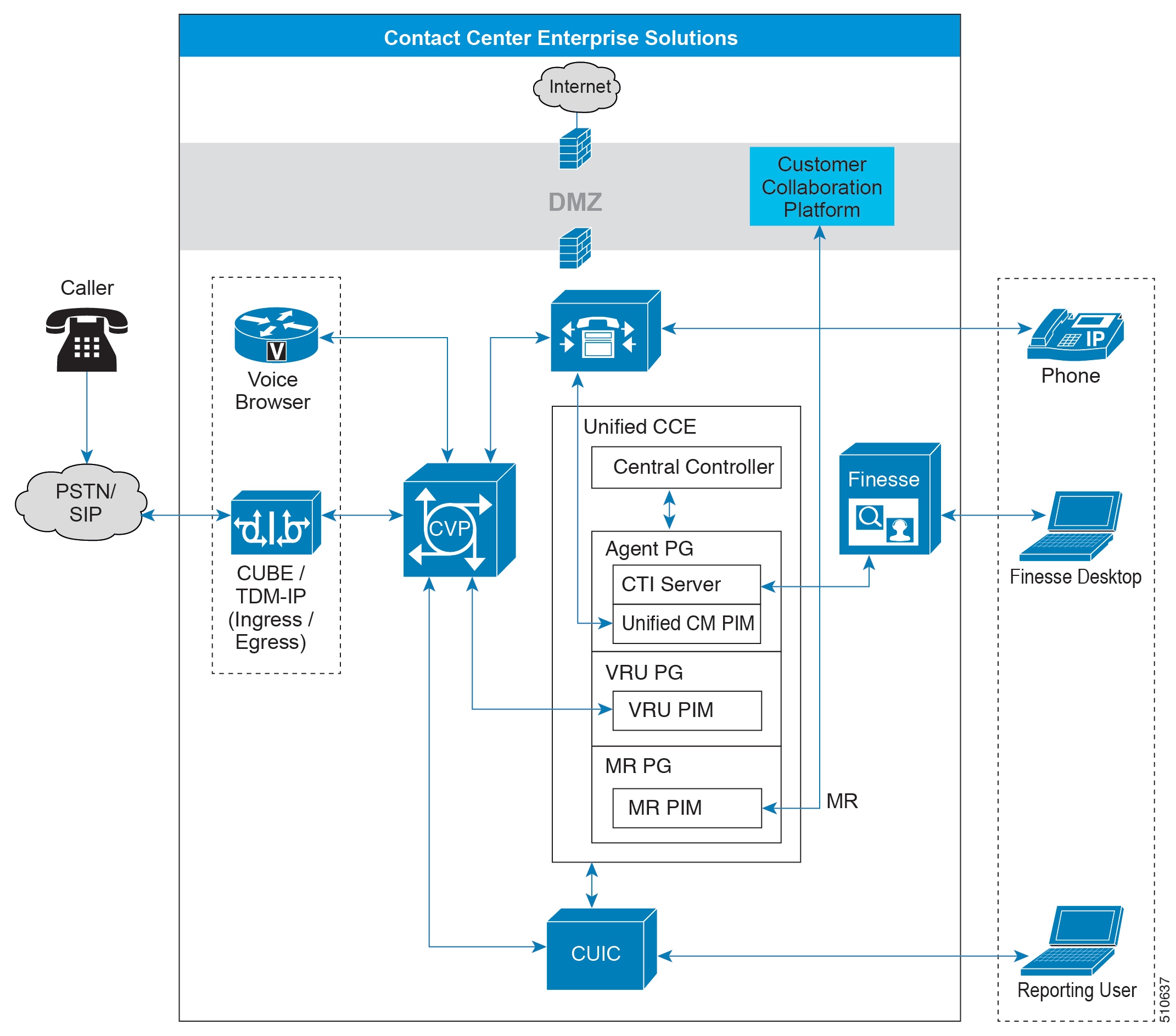
Figure 7. Unified CCE in a Contact Center Enterprise Solution
Unified CCE runs in VMs on Cisco Unified Computing System servers or exact equivalents. This table lists the major components of Unified CCE:
Table 1. Unified CCE Core Components
Unified CCE Software Components | Description | ||
|---|---|---|---|
CallRouter (Router) | Makes all routing decisions on how to route a call or customer contact. The Router is a part of the Central Controller. | ||
Logger | The database server that stores contact center configuration data. The Logger also temporarily stores historical reporting data for distribution to the data servers. The Logger is a part of the Central Controller. | ||
Peripheral Gateway (PG) | Interfaces to peripheral devices, like the Unified Communications Manager, VRU (Unified CVP), or multichannel products ( Enterprise Chat and Email or third-party multichannel applications that use the Task Routing APIs). The standard layout for contact center enterprise solutions has the Agent PG, VRU PG, and MR PG coresident on a single VM. Each PG includes one or more Peripheral Interface Managers (PIMs) for the specific device interfaces.
| ||
Administration & Data Server | Provides the configuration interface and real-time and historical data storage. You can deploy this component in several configurations. | ||
Live Data Server | Processes events from the Router and PGs for Unified CCE Live Data reports. |
- Terminology for Unified CCE Subcomponents
- Unified CCE
- Router
- Logger
- Peripheral Gateway
- Administration & Data Server
- Live Data
Terminology for Unified CCE Subcomponents
Combinations of these Unified CCE subcomponents are sometimes called by the following names:
Name | Description |
|---|---|
CCE Central Controller | Router and Logger |
CCE Rogger | Router and Logger running on same VM |
CCE Call Server | Router and PG |
CCE Data Server | Logger and AW |
Unified CCE
Use Unified UCCE for advanced call control, such as IP switching and transfers to agents. Both provide call center agent-management capabilities and call scripting capabilities. Scripts running in either environment can access Unified CVP applications.
Unified CCE
Unified CCE is the standard version that most solutions use. In these solutions, Unified CCE selects the agent who handles the call. Unified CM acts as the ACD.
Router
The Router is the brain of Unified CCE. When a call or task arrives, it triggers a routing script that decides what happens to the contact. The Router directs contacts from one place to another based on the script's outcome and selects the agent to handle the contact. Routers work in redundant pairs, referred to as Side A and Side B. Both sides are active. These separate, distributed instances use the Message Delivery Subsystem (MDS) to keep in lock-step with each other. Both sides share all data and control messaging so that both sides have the same data for routing decisions. The redundant deployment ensures that the system can operate even when one side fails. The opposite side continues routing contacts during an outage.
Logger
Unified CCE uses the Logger to store historical data and configuration data about the call center. The Logger collects the historical data and then distributes it later. Like the Router, you deploy the Logger as a redundant pair. Each side of the Logger only receives messages from the corresponding Router. For example, the Side A Router only sends messages to the Side A Logger. Because the routers run in lock-step, the Loggers on both sides receive the same messages during usual operation. After any outage, the Loggers resynchronize their data through the Routers. The Logger distributes historical data to the Historical Data Server (HDS). The Logger also distributes configuration and real time data to the Administration & Data Servers through Message Delivry Subsystem (MDS).
Depending on your solution, the Logger is on the same VM with the Router (a Rogger model) or on a separate VM (a Router/Logger model).
Peripheral Gateway
The peripheral gateway (PG) handles communication with telephony and multi-media devices through their CTI interfaces. PGs can communicate with ACDs, VRU devices, or IP PBXs. The PG normalizes the protocol of the assorted devices. The PG tracks the state of agents and calls that are on each device. The PG sends this status to the Router and forwards requests that require customer logic to the Router. A PG can include the following processes:
Peripheral Interface Managers (PIMs)
Computer Telephony Integration (CTI)
Java Telephony API (JTAPI)
In the standard layout for the Contact Center Enterprise Reference Designs , the Agent PG, VRU PG, and MR PG are coresident on a single VM. The PIMs handle the protocol normalization. The PIMs communicate to the peripheral and translate the peripheral proprietary language into one that Unified CCE understands. The CTI Gateway (CG - CTI Server component) is also coresident with the PG.
| Important | Your contact center enterprise solution can only use the new higher configuration limits with the standard three coresident PG layout. |
Unified CCE supports several types of PGs:
Agent PG—Connects to Unified Communications Manager (Unified CM)
Voice Response Unit (VRU) PG—Connects to CVP
Media Resource (MR) PG—Connects to multimedia components, like Enterprise Chat and Email or Customer Collaboration Platform
As with the other Unified CCE core components, you deploy PGs in redundant pairs.
One class of PG talks to an ACD or a Unified CM that has agents on it. These PGs use a proprietary CTI protocol to the switch, and maintain the state of agents and calls in queue on the device. Another class of PG exposes client-neutral interfaces. The VRU PG exposes an interface that is tailored to voice calls. The MR PG exposes an interface for more generic task routing.
Unified CCE treats the VRU and Unified CM as separate peripherals. This separation provides flexibility. You can load balance between several VRUs.
Larger, multisite (multicluster) deployments include many Agent PGs. In these deployments, Unified CCE tracks all the agents and calls centrally. Unified CCE can route calls to the most appropriate agent, independent of the site or cluster that they use. This coordination makes a logical enterprise-wide contact center with one enterprise-wide queue.
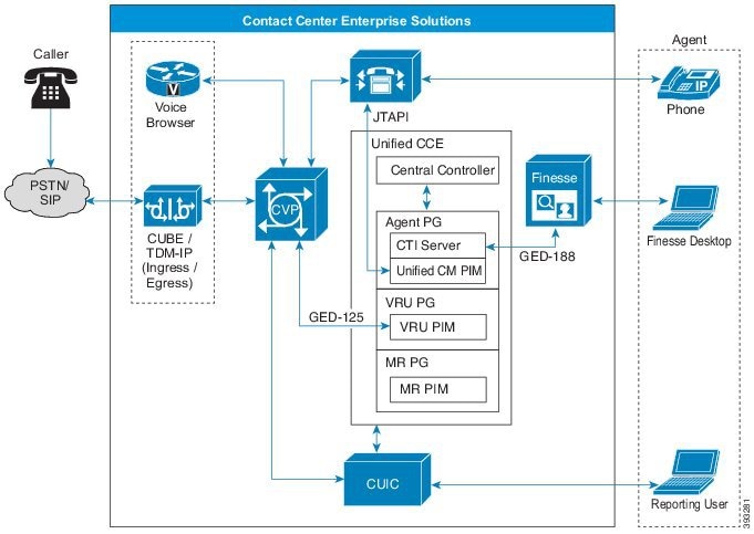
The following figure shows the communications between the PG and the other solution components.
Figure 8. Communications Between the PG and the Other Components
Peripheral Interface Managers
For each Unified CM cluster, there is a Unified CM PIM on an Agent PG. Each redundant Agent PG pair can support a maximum of 2000 agents. For scalability, some deployments require multiple PIMs for the same cluster. Deploy each PIM on a different Agent PG. Deploy only one Agent PG on each VM.
CTI Server
Each Agent PG includes a CTI server. The CTI Server handles call control and agent requests from the agent desktops. On the Agent PG, CTI services connect to one side or the other, depending on which side is active. The CTI Server processes agent state requests and updates the Central Controller for consideration in routing decisions. The PG forwards call control requests to the Unified CM, which monitors and controls the phone endpoints. The CTI Server keeps the agent desktop synchronized with the agent's IP phone state.
JTAPI Communications
The Unified CM PIM sign-in process establishes JTAPI communications between the Unified CM cluster and the application. The CTI Manager communicates through JTAPI to Unified CCE. Every subscriber within a cluster runs a CTI Manager instance. But, the Unified CM PIM on the PG communicates with only one CTI Manager (and thus one node) in the cluster. That connected CTI Manager passes CTI messages for the other nodes within the cluster. Each redundant pair of PGs shares a unique JTAPI user ID. The user ID is how the CTI Manager tracks the different applications.
For example, subscriber 1 connects to a Voice Gateway (VG) and subscriber 2 communicates with Unified CCE through the CTI Manager. When a call arrives at the VG, subscriber 1 sends an intra-cluster message to subscriber 2. Subscriber 2 sends a route request to Unified CCE to determine how to route the call.
The JTAPI communications between the cluster and Unified CCE include three distinct types of messaging:
Routing control—Messages that enable the cluster to request routing instructions from Unified CCE.
Device and call monitoring—Messages that enable the cluster to notify Unified CCE about state changes of a device (phone) or a call.
Device and call control—Messages that enable the cluster to receive instructions from Unified CCE on how to control a device (phone) or a call.
Most calls use all three types of JTAPI communications within a few seconds. When a new call arrives, Unified CM requests routing instructions from Unified CCE. When a subscriber receives the routing response from Unified CCE, the subscriber sends the call to an agent phone. The subscriber notifies Unified CCE that the phone is ringing. That notification enables the answer button on the agent desktop. When the agent clicks the answer button, Unified CCE instructs the subscriber to make the phone go off-hook and answer the call.
In order for the routing control communication to occur, the subscriber needs a CTI Route Point. You associate a CTI Route Point with a specific JTAPI user ID. Through this association, the subscriber knows which application provides routing control for that CTI Route Point. Dialed Numbers (DNs) are then associated with the CTI Route Point. Then, the subscriber can generate a route request to Unified CCE when a new call to that DN arrives.
| Note | You cannot use the DN for a CTI Route Point on a different CTI Route Point in another partition. Ensure that DNs are unique across all CTI Route Points on all partitions. |
Administration & Data Server
The Administration & Data Server is the main interface to the Unified CCE configuration. The Administration & Data Server includes a database with a copy of the configuration information from the Logger. The Administration & Data Server receives updates from the central controller to keep the database in sync. Clients can read the configuration from the database and send updates through the Central Controller. The main clients in the Administration & Data Server are the GUI configuration tools.
In production systems, install each Administration & Data Server on a separate VM from the Router and Logger to ensure no interruptions in the real-time call processing. In contact center enterprise lab systems, you can install the Administration & Data Server on the same VM as the Router and Logger.
For information about data storage in virtualized deployments, see the Virtualization for Unified Contact Center Enterprise at http://www.cisco.com/c/dam/en/us/td/docs/voice_ip_comm/uc_system/virtualization/virtualization-unified-contact-center-enterprise.html.
You can deploy the Administration & Data Server in a combination of roles to achieve the proper scalability for your deployment:
Administration Server and Real-Time Data Server (AW)
Administration Server and Historical Data Server (AW-HDS)
Administration Server, Historical Data Server, and Detail Data Server (AW-HDS-DDS)
Historical Data Server and Detail Data Server (HDS-DDS)
You do not deploy the Administration & Data Server in redundant pairs like the other core components. Instead, you deploy one Administration & Data Server for each Logger. If one Administration & Data Server fails, you can sign in your client AW to another server.
The AW acts as the authentication server for Cisco Finesse. In a Cisco Finesse deployment, the AW is mandatory and must run in high-availability mode (both a primary and backup AW).
- Administration Server and Real-Time Data Server (AW)
- Historical Data Server and Detail Data Server (HDS-DDS)
- Administration Server and Historical Data Server (AW-HDS)
- Administration Server, Historical Data Server, and Detail Data Server (AW-HDS-DDS)
Administration Server and Real-Time Data Server (AW)
This server handles configuration changes and real-time reporting with Cisco Unified Intelligent Center (Reporting client). The Real-Time Data Server portion of the AW uses the AW database to store real-time data and configuration data. Real-time reports combine these two types of data to present a near-current snapshot of the system. This role does not support historical reporting. System administrators generally use AWs to control access to what a configuration user can configure.
Figure 9. Configuration and Real-Time Reporting AW
You can deploy an AW to handle only configuration tasks for scalability in these models:
Configuration-Only Administration Server
Administration Client (formerly called a client AW)
For these configuration-only models, real-time reporting is turned off.
This deployment role allows Unified CCMP to configure a specific Unified CCE Customer Instance. The load is low enough on such a lightweight Administration & Data Server that a single server is sufficient.
Figure 10. Configuration-Only AW
Configuration Only Administration Servers are the same as AWs, but without the real-time data. As such, Administration Clients cannot connect to them and they cannot display real-time data in Script Editor.
An Administration Client (formerly known as a client AW) serves the administration role but is deployed as a client to an Administration Server for scalability. The Administration Client can view and modify the configuration and receive real-time reporting data from the AW. But, it does not store the data itself and does not have a database.
The AW supports configuration tools for such tasks as creating agents, skill groups, precision queues, and routing scripts.
The primary AW communicates directly with the Central Controller for configuration data. You can set up secondary AWs to provide scaling for real-time reporting. During usual operation, the secondary AW connects to the primary AW for the data. If the primary AW fails, the secondary AW connects to the Central Controller.
You can deploy AWs coresident with the Central Controller or remotely. You can deploy the primary and secondary AWs together or separately.
If you use Administration Clients, you can deploy and connect multiple Administration Clients to either the primary or the secondary AWs. But, deploy them geographically local to their AW.
| Note | Administration Clients and Administration Workstations can support remote desktop access. But, only one agent can access a client or workstation at a time. Unified CCE does not support simultaneous access by several users on the same client or workstation. |
Historical Data Server and Detail Data Server (HDS-DDS)
The role handles only data extraction and custom reports for call detail (TCD and RCD) records. You can only have one server of this type on each side of a redundant Logger pair. This role does not support these features:
Real-time data reporting
Configuration changes
Figure 11. Historical Data Server and Detail Data Server (HDS-DDS)
The Historical Data Server (HDS) and the Detail Data Server (DDS) provide longer-term historical data storage. The HDS stores historical data summarized in 15- or 30-minute intervals for reporting. The DDS stores detailed information about each call or call segment for call tracing. You can extract data from either source for warehousing and custom reporting.
Typically, you deploy these Data Servers with a primary AW as a single server serving all three roles (AW-HDS-DDS). You use the HDS-DDS in large deployments where separating their function from the AW aids scalability.
Administration Server and Historical Data Server (AW-HDS)
This role handles configuration changes, real-time reporting, and historical reporting. This server uses the Cisco Unified Intelligent Center Reporting user for real-time and historical reporting. This role does not support these features:
Call Detail, Call Variable, and Agent State Trace data
Custom reporting data extraction
Figure 12. Administration Server and Historical Data Server (AW-HDS)

The Real-Time Data Server uses the AW database to store real-time data and configuration data. Real-time reports combine these two types of data to present a near-current snapshot of the system.
The Historical Data Server (HDS) provides longer-term historical data storage. The HDS stores historical data summarized in 15- or 30-minute intervals for reporting. You can extract data from the HDS for warehousing and custom reporting.
Figure 13. Communication Between Central Controller and Administration & Data Server
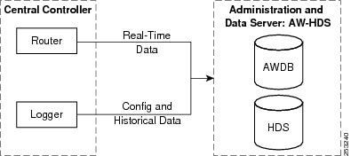
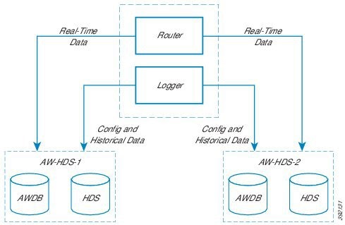
Figure 14. Communication Between Central Controller and Multiple Administration & Data Servers
Administration Server, Historical Data Server, and Detail Data Server (AW-HDS-DDS)
This role handles configuration changes, real-time reporting, and historical reporting, like the AW-HDS role. This server uses the Cisco Unified Intelligent Center (Unified Intelligence Center Reporting client) for real-time and historical reporting. This server also provides call detail and call variable data for custom reporting data extraction to feed historical data.
Figure 15. Administration Server, Historical Data Server, and Detail Data Server (AW-HDS-DDS)
The Real-Time Data Server uses the AW database to store real-time data and configuration data. Real-time reports combine these two types of data to present a near-current snapshot of the system.
The Historical Data Server (HDS) and the Detail Data Server (DDS) provide longer-term historical data storage. The HDS stores historical data summarized in 15- or 30-minute intervals for reporting. The DDS stores detailed information about each call or call segment for call tracing. You can extract data from either source for warehousing and custom reporting.
Data Purge
Data beyond the configured retention time is purged automatically at 12:30 AM and uses the time zone setting of the core server. The purge also triggers when the database reaches 80% and 90% of its maximum size.
Follow Cisco supported guidelines to run the purge at off-peak hours or during a maintenance window.
Note that you can control or change the automatic purge schedule through the command line interface. You can change it if the automated purge does not occur during your off-peak hours.
The purge has a performance impact on the Logger.
Live Data
Live Data is a data framework that processes real-time events with high availability for Live Data reports. Live Data continuously processes agent and call events from the peripheral gateway and the router. As events occur, Live Data continuously pushes real-time updates to Unified Intelligence Center reporting clients. This table lists the placement of the Live Data services in the Reference Designs .
2000 Agent | 4000 Agent | 12000 Agent | 24000 Agent | Contact Director | |
|---|---|---|---|---|---|
Live Data placement | Colocated on a VM with Unified Intelligence Center and the Cisco Identity Service | Located on a standalone VM | Located on a standalone VM | Located on a standalone VM | The Contact Director does not have Live Data installed. Live Data is on the target Unified CCE instances. |
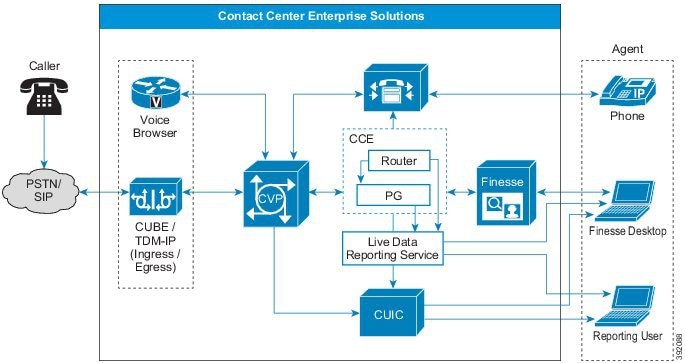
The PG and the Router push agent and call events to Live Data as the events occur. Live Data then continuously aggregates and processes the events in-stream and publishes the information. Unified Intelligence Center subscribes to the message stream to receive the events in real-time and continuously update Live Data reports. Individual state values, such as agent states, refresh as they happen. Other values, such as calls in queue, refresh approximately every 3 seconds.
Live Data resides in Unified CCE on a Cisco Voice Operating System (VOS) VM. You can embed Live Data reports in Finesse agent desktops.
| Note | Live Data requires that both Cisco Unified Intelligence Center and Cisco Finesse use the same transfer protocol. By default, both use HTTPS. |
Cisco Virtualized Voice Browser
Cisco Virtualized Voice Browser (Cisco VVB) provides a platform for interpreting VXML documents. When an incoming call arrives at the contact center, Cisco VVB allocates a VXML port that represents the VoIP endpoint. Cisco VVB sends HTTP requests to the Unified CVP VXML server. The Unified CVP VXML server performs the request and sends back a dynamically generated VXML document.
Cisco Unified Communications Manager
Cisco Unified Communications Manager (Unified CM) is the main call processing component of a Cisco Collaboration System. It manages and switches VoIP calls among IP phones. Unified CVP interacts primarily with Unified CM as a means for sending PSTN-originated calls to Unified CCE agents.
The following common scenarios require calls to Unified CVP to originate from Unified CM endpoints:
An office worker (not an agent) on an IP phone dials an internal help desk number.
An agent begins a consultative transfer that gets routed to a Unified CVP queue point.
Unified CM communicates with Unified CCE through the Java Telephony Application Programming Interface (JTAPI). In a fault-tolerant design, a Unified CM cluster supports thousands of agents. The number of agents and the number of busy hour call attempts (BHCA) supported within a cluster varies and must be sized according to Cisco guidelines.
Typically, when designing a Unified CCE solution, you first define the deployment scenario. You determine the arrival point (or points) for the voice traffic and the location (or locations) of the contact center agents. You then determine the sizing of the individual components within the Unified CCE design. This step includes determining how many Unified CM clusters and servers within each cluster are needed.
You can add a 2000 Agent Reference Design solution to an existing Unified CM deployment. In this case, the existing Unified CM cluster is an off-box replacement of the on-box cluster in the standard Reference Design layout. With this configuration, two of the subscribers must be dedicated to CCE. All devices on these subscribers must be SIP. In the global topology, each remote site can have its own Unified CM cluster.
| Note |
|
In a Unified CVP environment, Unified CM can be an Ingress or Egress Gateway. It is more common for Unified CM to be an Egress Gateway. Calls typically are from the PSTN, queued by Unified CVP, and then switched to Unified CM for handling by an agent. If the call is from an IP phone, not a PSTN, the Unified CM is an Ingress Voice Gateway from the perspective of Unified CVP.
- Unified CM as an Egress Gateway
- Unified CM Ingress Gateway
- Call Processing Nodes
- TFTP and Music on Hold Nodes
Unified CM as an Egress Gateway
To deploy Unified CM with Unified CVP, use Unified CM call admission control for calls between the Ingress Voice Gateway and the agent IP phone. Unified CM recognizes the call coming from the centralized Unified CVP Call Server instead of from the Remote Ingress Voice Gateway.Unified CM Ingress Gateway
When an IP phone initiates a call to Unified CVP, the Unified CM acts as the Ingress Voice Gateway to Unified CVP. A SIP trunk is used to send calls to Unified CVP.Call Processing Nodes
Cisco Unified Communications Manager serves as the software-based call-processing component of the Cisco Unified Communications family of products.
The Unified CM system extends enterprise telephony features and functions to packet telephony network devices such as IP phones, media processing devices, voice-over-IP (VoIP) gateways, and multimedia applications. Unified CM provides signaling and call control services to Cisco-integrated telephony applications and third-party applications. Unified CM performs the following primary functions:
Call processing
Signaling and device control
Dial plan administration
Phone feature administration
Directory services
Operations, administration, maintenance, and provisioning (OAM&P)
Programming interface to external voice-processing applications such as Cisco IP Communicator, Cisco Unified Customer Voice Portal (CVP)
The Unified CM system includes a suite of integrated voice applications that perform voice-conferencing and manual attendant console functions. This suite of voice applications means that no need exists for special-purpose voice-processing hardware. Supplementary and enhanced services such as hold, transfer, forward, conference, multiple line appearances, automatic route selection, speed dial, last-number redial, and other features extend to IP phones and gateways. Because Unified CM is a software application, enhancing its capabilities in production environments requires only upgrading software on the server platform, avoiding expensive hardware upgrade costs.
Distribution of Unified CM and all Cisco Unified IP Phones, gateways, and applications across an IP network provides a distributed, virtual telephony network. This architecture improves system availability and scalability. Call admission control ensures that voice quality of service (QoS) is maintained across constricted WAN link. It automatically diverts calls to alternate public switched telephone network (PSTN) routes when WAN bandwidth is not available.
A browser interface to the configuration database provides the capability for remote device and system configuration. This interface also provides access to HTML-based online help for users and administrators.
Unified CM, designed to work like an appliance, refers to the following functions:
Unified CM servers can get preinstalled with software to ease customer and partner deployment. They automatically search for updates and notify administrators when key security fixes and software upgrades are available for the system. This process comprises Electronic Software Upgrade Notification.
You can upgrade Unified CM servers while they continue to process calls, so upgrades take place with minimal downtime.
Unified CM supports the Asian and Middle Eastern markets by supporting Unicode on higher resolution phone displays.
Unified CM provides Fault, Configuration, Accounting, Performance, and Security (FCAPS).
TFTP and Music on Hold Nodes
A TFTP subscriber or server node performs two main functions as part of the Unified CM cluster:
The serving of files for services to devices such as phones and gateways. This includes configuration files, binary files for upgrades, and various security files.
Generation of configuration and security files. These are signed and sometimes encrypted before being made available for download.
You can enable the Cisco TFTP service that provides this functionality on any server in the cluster. In a cluster with more than 1250 users, configuration changes that cause the TFTP service to regenerate configuration files can affect other services. In such clusters, dedicate a specific subscriber node to the TFTP service and MOH feature or any features that cause frequent configuration changes.
Use the same hardware platform for the TFTP subscribers as used for the call processing subscribers.
A Unified Communications Manager MoH server can generate a MoH stream from two types of sources, audio file and fixed source. Either source can be transmitted as unicast or multicast.
Cisco Finesse
Cisco Finesse is the next-generation agent and supervisor desktop for Cisco Unified Contact Center Enterprise, providing benefits across various communities that interact with your customer service organization. It is designed to improve collaboration by enhancing the customer and customer service representative experience.
The Cisco Finesse agent and supervisor desktop for Cisco Unified Contact Center Enterprise integrates traditional contact center functions into a thin-client desktop. A critical characteristic is that every desktop is browser-based and implemented through a Web 2.0 interface. No client-side installations are required. This reduces the total cost of ownership (TCO).
Cisco Finesse also provides a Web 2.0 software development kit (SDK) and gadgets to enable developers to quickly implement the desktop.
You deploy the Cisco Finesse server on a dedicated VMware virtual machine (VM) that runs on the Cisco Voice Operating System (VOS) platform. The Cisco Finesse server is a required component for the Cisco Finesse desktop solution. The Cisco Finesse software is fault-tolerant and deploys on redundant VMs. Both Cisco Finesse servers are simultaneously active. One Cisco Finesse server acts as a publisher and replicates configuration data to the subscriber in the redundant pair.
The Cisco Finesse server connects to the CTI server on the Agent PG. Authentication with Unified CCE is provided over a connection to the Administration & Data Server. If you enable Single Sign-On (SSO), the Cisco Identity Service provides authentication.
Figure 17. Cisco Finesse in a Contact Center Enterprise Solution
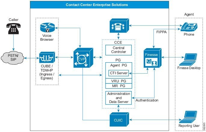
Cisco Finesse requires that you deploy the Administration & Data Server with a backup Administration & Data Server. If the primary Administration & Data Server goes down, Cisco Finesse connects to the backup server for authentication so that agents can still sign in.
The Cisco Finesse server exposes supported client operations through a Representational State Transfer (REST) API. The REST API shields the developer from many of the details surrounding the CTI server wire protocol.
Cisco Finesse clients connect to the Cisco Finesse server over a web browser that points to the fully qualified domain name (FQDN) of the Cisco Finesse server.
You deploy the Cisco Finesse server in an active/active deployment, where both Cisco Finesse servers connect to the active CTI server on the Agent PG. The standard Cisco VOS replication mechanism provides redundancy for persistent configuration data on the Cisco Finesse servers.
Cisco Finesse Server Services
You can access the following Cisco Finesse services using the CLI:
Cisco Finesse Notification service—This service is used for messaging and events. The Cisco Finesse desktop uses this service to view call events, agent state changes, and statistics.
Cisco Finesse Tomcat service—This service contains all deployed Cisco Finesse applications. These applications include the following:
Cisco Finesse desktop application: This application provides the user interface for agents and supervisors.
Cisco Finesse IP Phone Agent application: This application allows agents and supervisors to perform Cisco Finesse operations on their Cisco IP Phone.
Cisco Finesse REST API application: Cisco Finesse provides a REST API that enables client applications to access the supported server features. The REST API can use HTTPS to transport application data. The REST API also provides a programming interface that third-party applications can use to interact with Cisco Finesse. See the Cisco Finesse documentation at https://developer.cisco.com/site/finesse/ for more information on the REST API.
Cisco Finesse administration application: This application provides the administrative operations for Cisco Finesse.
Cisco Finesse Diagnostic Portal application: This application provides performance-related information for Cisco Finesse.
Agent Mobility
The Unified CCE deployment does not statically associate the agent desktop with any specific agent or IP phone extension. You configure agents and phone extensions within Unified CCE and associate them with a specific Unified Communications Manager cluster.
When agents sign in to their desktop, a dialog prompts for an agent ID or username, password, and the phone extension to use for that session. Then, the agent ID, phone extension, and agent desktop IP address are dynamically associated. The association is released when the agent signs out.
This mechanism allows an agent to work (or hot-desk) at any workstation. The mechanism also allows agents to take their laptops to any appropriately configured Cisco Unified IP Phone and sign in from that device.
Agents can also sign in to other phones using the Cisco Extension Mobility feature. For more information about this feature, see the Extension Mobility section of the Feature Configuration Guide for Cisco Unified Communications Manager at http://www.cisco.com/c/en/us/support/unified-communications/unified-communications-manager-callmanager/products-installation-and-configuration-guides-list.html.
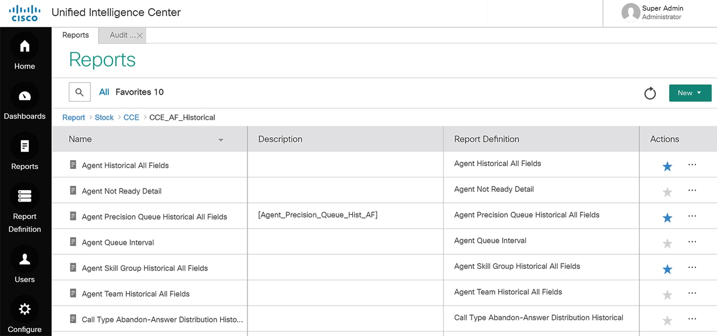
Cisco Unified Intelligence Center
Cisco Unified Intelligence Center (Unified Intelligence Center) is a web-based reporting application that provides easily consumable Live Data, real-time, and historical reporting for Unified CCE and Unified CVP. It allows supervisors and business users to report from a single interface on the details of multichannel contacts across the solution. You can extend the boundaries of traditional reporting to an information portal where you can integrate and share data throughout the organization.
You deploy the Unified Intelligence Center server on a dedicated VM that runs on the Cisco Voice Operating System (VOS) platform. In the 2000 Agent Reference Design, Unified Intelligence Center is coresident with Live Data and the Cisco Identity Service.
Unified Intelligence Center offers high scalability, performance, and advanced features such as data integration with other Cisco Unified Communications products or third-party data sources. Unified Intelligence Center incorporates a security model that defines different access and capabilities for specific users.
Cisco Unified Intelligence Center offers both a web-based reporting application and an administration interface. Unified Intelligence Center reporting capabilities include the following:
Dashboard mashups
Powerful grid presentations of reports with sorting and grouping
Chart and gauge presentations of reports
Association of multiple report displays with the same report definition
Custom filters
Custom thresholds to alert on the data
Stock report templates for contact center enterprise data
Ability to report data from MS SQL Server and Informix databases
Administrators can use Unified Intelligence Center to control access to features, reports, and data by granting privileges only to authorized individual users or groups of users. For example, you can assign each supervisor to a group of agents, skills, and call types that are the most relevant to them. This allows each report to provide focused, actionable insights into data that is appropriate to their role.
Several features in this product allow you to extend the Unified Intelligence Center platform beyond traditional reporting and into an enterprise-wide information portal. You can use data from nontraditional sources to improve business efficiency and effectiveness.
The Unified CCE Reporting solution provides an interface to access Live Data, real-time, and historical data for the contact center.
The reporting solution consists of the following components:
Cisco Unified Intelligent Center—Reporting user interfaces
Configuration and Reporting Data—Contained on one or more Administration & Data Servers
Figure 18. Unified Intelligence Center
Optional Cisco Components
Some contact center enterprise solutions use these optional Cisco components. You add them to a solution when you want the functionality that they offer. Usually, these optional components require extra servers.
Cisco Customer Collaboration Platform
Cisco Customer Collaboration Platform provides the means to route digital media requests to agents in your contact center. Your solution can use Customer Collaboration Platform for the following:
The Agent Request feature which allows a customer to initiate a request a call from an agent from a web site. For more information on this feature, see the Cisco Unified Contact Center Enterprise Features Guide at http://www.cisco.com/c/en/us/support/customer-collaboration/unified-contact-center-enterprise/products-feature-guides-list.html.
The Task Routing APIs which you can use to integrate third-party multichannel applications.
Figure 19. Customer Collaboration Platform in Contact Center Enterprise Solutions
Task Routing
Task Routing describes the system's ability to route requests from different media channels to any agents in a contact center.
You can configure agents to handle a combination of voice calls, emails, chats, and so on. For example, you can configure an agent as a member of skill groups or precision queues in three different Media Routing Domains (MRD) if the agent handles voice, e-mail, and chat. You can design routing scripts to send requests to these agents based on business rules, regardless of the MRD from which the request came. Agents logged into multiple MRDs may switch media on a task-by-task basis.
The optional component Enterprise Chat and Email provides Task Routing out of the box. Third-party multichannel applications can use Task Routing by integrating with CCE through the Task Routing APIs.
Task Routing APIs provide a standard way to request, queue, route, and handle third-party multichannel tasks in CCE.
Contact Center customers or partners can develop applications using Customer Collaboration Platform and Finesse APIs in order to use Task Routing . The Customer Collaboration Platform Task API enables applications to submit nonvoice task requests to CCE. The Finesse APIs enable agents to sign into different types of media and handle the tasks. Agents sign into and manage their state in each media independently.
Cisco partners can use the sample code available on Cisco DevNet as a guide for building these applications (https://developer.cisco.com/site/task-routing/).
Cisco Unified SIP Proxy
The Cisco Unified SIP Proxy (CUSP) is a high-performance, highly available Session Initiation Protocol (SIP) server for centralized routing and SIP signaling normalization. By forwarding requests between call-control domains, CUSP enables you to route sessions within enterprise and service provider networks. The application aggregates SIP elements and applies highly developed routing rules. These rules enhance control, management, and flexibility of SIP networks.
Unified CVP supports only the CUSP Server.
In a Unified CVP deployment, a CUSP Server sees incoming calls from the TDM Gateway, from Unified CVP, and from the UCM SIP trunk. With a SIP back-to-back user agent in CVP, the initial call setup from the proxy involves an inbound call immediately followed by an outbound call (whether for VRU or to ACD). Later in the call, CVP may transfer the call to an agent, which involves an outbound leg, and reinvites to the inbound leg. A ringtone service setup is also available which also involves a separate outbound call and a reinvite to the caller. Reinvites on the caller leg occur at CVP transfer or during supplementary services.
Figure 20. CUSP in a Contact Center Enterprise Solution
The CUSP Server routes SIP messages among SIP endpoints. The CUSP Server enables solution wide SIP-endpoint high availability and load balancing. The CUSP Server is designed to support multiple SIP endpoints of various types and to implement load balancing and failover among these endpoints. Deployment of a SIP proxy in the solution enables a more centralized configuration of the dial plan routing configuration.
You can configure a SIP proxy with multiple static routes to do load balancing and failover with outbound calls. The static routes can point to an IP address or a DNS.
Domain Name System (DNS) Service Record (SRV) is not qualified for use on the CUSP Server. However, you can use it for the devices that must reach the CUSP Server, such as Unified CVP, Ingress Voice Gateway, and Unified CM.
You can deploy Unified CVP without a CUSP Server, depending on the design and complexity of the solution. In such cases, some of the functions that a CUSP Server provides are provided by the Unified CVP Server SIP service.
Following are the benefits of using a CUSP Server:
You can use priority and weight routing with the routes for load balancing and failover.
If a CUSP Server exists in your SIP network, then Unified CVP acts as an additional SIP endpoint. The Unified CVP fits incrementally into the existing SIP network.
If you do not use a CUSP Server, then the Ingress Voice Gateways and Unified CMs must point directly to Unified CVP. In such a deployment, perform the following tasks:
Perform load balancing using DNS SRV lookups from gateway to DNS Server; balance SIP calls using this procedure.
Perform load balancing of calls outbound from Unified CVP (outbound call leg) using DNS SRV lookups.
Enterprise Chat and Email
The contact center enterprise solutions use Enterprise Chat and Email ( ECE ) to provide a multichannel contact center.
For email, ECE enables organizations to intelligently route and process inbound emails, webform inquiries, faxes, and letters. For web-chat, ECE provides agents with a comprehensive set of tools for serving customers in real time. It enables call center agents to provide immediate personalized service to customers through text chat messaging and page-push abilities.
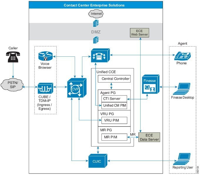
Deploy the ECE Web Server on an external server. You can place that server either in the same site as the ECE Data Server or in a DMZ if customer chat interactions require that.
Figure 21. ECE in Contact Center Enterprise Solutions
Enterprise Chat and Email Features
Following are the Enterprise Chat and Email (ECE) features.
ECE supports email to create a communication channel between a customer and an agent. There are various steps involved in efficiently responding to emails from customers. Emails are first retrieved into the system and routed to appropriate users or queues. Once a response is created, it is processed through the system and sent to the customer.
Chat
It is an activity created for a chat session between a customer and an agent. A chat is a real time interaction between an agent and a customer during which they exchange text messages. As part of a chat, agents can also push web pages to customers. Based on how chat activities are routed to agents, they can be categorized as Standalone chats and Integrated chats. An integrated chat is routed to an integrated queue, and a message is sent to Unified CCE. Unified CCE processes the activity and assigns the chat to an available agent.
Web Callback and Delayed Callback
The Web Callback feature allows you to request a callback by submitting a form on a website. ECE processes the submitted information and connects the user with an agent. In the contact center enterprise integration, the ECE sends a message to Unified CCE requesting Unified CCE to route the callback request to an agent. Unified CCE sends a message to ECE. When an agent is available, the Call Router notifies the agent to begin the Web Callback.
The Delayed Callback feature is similar to the Web Callback feature. When the ECE receives the delayed callback request, it adds the request in the Delayed Callback table. ECE sends the HTML page to the caller that tells the timeframe for the callback. When the specified time arrives, ECE moves the request to the Unified CCE queue for routing to Unified CCE. The call is then processed the same way as for Web Callback.
Cloud Connect
Cloud Connect is a new component that allows customers to use cloud services such as Webex Experience Management. The administrator can configure the Cloud Connect server settings in Unified CCE Administration to contact the Cisco cloud services.
For information on how to configure Cloud Connect, see the Cisco Packaged Contact Center Enterprise Administration and Configuration Guide at https://www.cisco.com/c/en/us/support/customer-collaboration/packaged-contact-center-enterprise/products-maintenance-guides-list.html
Third-Party Components
You can extend the functionality of your contact center enterprise solution with third-party components.
Load Balancers
In Contact Center Enterprise Reference Designs , load balancers are used in redirect mode only. You can use third-party load balancers for the following purposes in your contact center enterprise solution:
For access to the Cisco Finesse sign-in page
When you use the Finesse REST API directly
With Unified CVP
For access to the Unified CCE Administration tool sign-in page
When you use the Unified CCE Administration REST API directly
With Cisco Unified Intelligence Center
With Cisco Unified Intelligence Center Administration Console
For more information on load balancer requirements, see the Compatibility Matrix for your contact center enterprise solution.
Recording
The Recording option provides network-based storage of media, including audio and video, with rich recording metadata. You can record, play back, and live stream the media. You can use this option for compliance, quality management, and agent coaching. The platform provides an efficient, cost-effective foundation for capturing, preserving, and mining conversations for business intelligence.
| Note | Unified CVP has a network-based recording (NBR) feature to support software-based forking for Real-time Transport Protocol (RTP) streams. |
| Note | For ERSPAN support on UCS B Series for any third-party recording application, consult the vendor's application requirements. |
Speech Servers - ASR/TTS
Automatic Speech Recognition (ASR) Server and Text-to-Speech (TTS) Server provides speech recognition services and text-to-speech services for a Voice Browser. Automatic Speech Recognition (ASR) enables callers to verbally choose menu options. For example, an Automated Attendant can ask who you are calling and then use your reply to connect the call. Text-to-Speech (TTS) converts plain text (UNICODE) into speech. For example, Voice Browsers can stream media from a text-to-speech (TTS) server.
ASR/TTS license use depends on what you use for a voice browser. The VXML Gateway does not release the ASR/TTS license until the end of a call. Cisco VVB releases the license when the script no longer requires it.
Figure 22. Speech Servers in Contact Center Enterprise Solutions
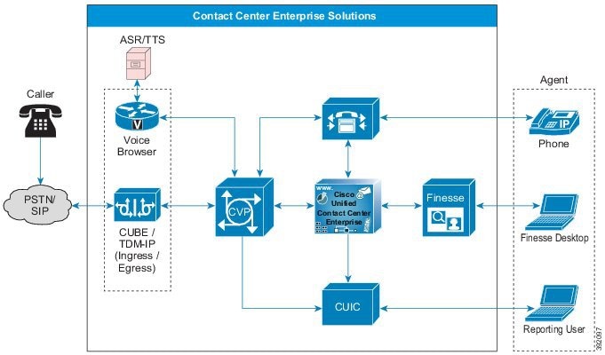
Communication between the ASR and TTS servers and the Voice Browser uses Media Resource Control Protocol (MRCP). See the Compatability Matrix for details on the support for MRCP versions.
The World Wide Web Consortium (W3C) provides a rich feature set to support the ASR grammars. You can implement and support inline grammars which pass the set of acceptable customer responses to the Voice Browser. You can also use external grammars, where Unified CCE passes a pointer to an external grammar source. The VXML Server adds this pointer to the VXML document that it sends to the Voice Browser. The Voice Browser then uses the grammar to check ASR input from the caller. In this case, the customer creates the grammar file. A third type of grammar is the built-in grammar. For a complete explanation of grammar formats, see the W3C website at http://www.w3.org/TR/speech-grammar/.
When the VXML Server directly passes the text for TTS to the gateway, we refer to the action as inline TTS. A separate server that communicates with the Voice Browser through MRCP performs the speech recognition and speech synthesis. The ASR and TTS engine also supports (with limitations) voice recognition and synthesis for multiple languages.
For information on third-party ASR or TTS software and servers, see your solution's Compatibility Matrix.
Wallboards
Wallboards enable you to monitor, in real time, the service that you are providing to your customers. Wallboards display information on customer service metrics such as number of calls waiting, waiting call length, and Service levels.
Workforce Management
Workforce Management (WFM) enables you to schedule multiple queues and sites. You can use a single WFM implementation worldwide. WFM also enables you to manage key performance indicators and real-time adherence to schedules.
Your users (agent, supervisor, scheduler, and administrator) can access WFM with a web browser. Because you avoid the installation of a thick client, WFM is ideally suited to a highly distributed workforce environment.
Integrated Features
The difference between optional components and integrated features is the ease of adding them to your solution. In general, an integrated feature does not require you to add a server or VM to your solution. You only configure it to activate it in your solution. But, remember that these features can have significant sizing or other design impacts.
You can find more information on various integrated features in your solution's Feature Guide.
- Agent Greeting
- Application Gateway
- Business Hours
- Cisco Outbound Option
- Courtesy Callback
- Call Context
- Database Integration
- Database Lookup
- Extension Mobility
- Mixed Codecs
- Mobile Agent
- Phone Extension Support
- Post Call Survey
- Cisco Webex Experience Management
- Precision Routing
- Single Sign-on (SSO)
- Whisper Announcement
Agent Greeting
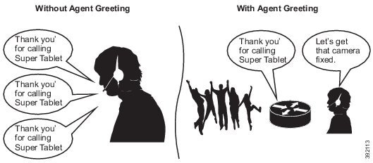
With Agent Greeting, you can play a configurable, automated greeting to callers. Every caller receives a clear, well-paced, language-appropriate, and enthusiastic introduction from the answering agent. Agent Greeting relieves your agents from speaking opening scripts. Instead, your agents can spends the time reviewing the desktop screen pop-ups while the greeting plays.
Recording a greeting is much the same as recording a message for voice mail. Depending on how you set up the call center, agents record different greetings that play for different types of callers (for example, an English greeting for English speakers or an Italian greeting for Italian speakers).
Agent Greeting is available to agents and supervisors who use IP Phones with Built-in-Bridge (BiB) that are controlled by the Unified CCE and Unified CM.
Figure 23. Agent Greeting
Application Gateway
The Application Gateway provides an interface for the CCE routing engine to query an external service. It requires a custom application to be written that uses the Application Gateway protocol, GED-145, which is open to our development partners. For more information, see https://developer.cisco.com/site/devnet/home/index.gsp.
Application Gateway allows you to insert application gateway nodes in their scripts. These nodes help you to populate variables and send requests to the custom application, and retrieve relevant information. The information can be used in administrative scripts to open or close programs. It can also return relevant customer data in a routing script which can be sent to the agent.
Business Hours
The Business Hours feature lets you create schedules for regular working hours and extra working hours, and to close the contact center for holidays or emergencies. It provides the mechanism for routing these contacts to specific support teams based on the configured work hour schedules, holidays, emergency closures, or extra working hours. You can create Business Hour schedules for various scenarios for various contact center teams. This feature helps you create and apply several Business Hour schedules to the same team. On the other hand, you could apply the same Business Hour schedule to several support teams.
When a customer contacts the contact center, the response by the contact center is based on the status of the support team. This status is evaluated using the Business Hour configured for the team.
Cisco Outbound Option
In contact center enterprise solutions, agents can handle both inbound and outbound contacts. Contact center managers in need of outbound campaign solutions can take advantage of the enterprise view that Cisco Unified CCE maintains over agent resources. Cisco Outbound Option supports agent-based and VRU-based campaigns. For agent-based campaigns, it also supports transfer of calls to a VRU for answering machines or to meet regulatory requirements for abandoned calls. A VRU campaign does not use agents, instead the call is directed to a VRU which plays a recorded message to answered calls.
The Cisco Outbound Option Dialer provides outbound dialing functionality along with the existing inbound capabilities of the Cisco Unified Contact Center Enterprise. This application enables the contact center to dial customer contacts and direct contacted customers to agents. With Cisco Outbound Dialer, you can configure a contact center for automated outbound activities.
The Outbound Option Dialer is a software-only process that coresides on the Unified CM PG. The SIP Dialer process communicates with Voice Gateways or CUBE, Outbound Option Campaign Manager, CTI Server, and MR PIM. The Dialer communicates with the Campaign Manager to retrieve outbound customer contact records and to report outbound call disposition (including live answer, answering machine, RNA, and busy). The Dialer communicates with the Voice Gateway to place outbound calls. The Dialer communicates with the CTI Server to monitor skill group activity and to perform third-party call control for agent phones. The SIP Dialer communicates with the MR PIM to submit the route requests to select an available agent.
The Outbound Option Dialer can dial customers on behalf of all agents located on its peripheral. The Dialer is configured with routing scripts that can run in the following modes:
Full blended mode-An agent can handle inbound and outbound calls
Scheduled modes-For example, 8:00 a.m. to 12:00 p.m. (0800 to 1200) in inbound mode and 12:01 to 5:00 p.m. (1201 to 1700) in outbound mode
Completely in outbound mode
If blended mode is enabled, the Dialer competes with inbound calls for agents. The Dialer does not reserve more agents than are configured in the administrative script Outbound Percent variable. If all agents are busy, then the Dialer does not attempt to reserve any additional agents.
You can deploy Outbound Option in several ways to achieve more or less high availability:
Single Campaign Manager, Outbound Option Import, and Database—This is a non-fault tolerant configuration of the subcomponents that direct operation of the SIP Dialers. If the Campaign Manager or Outbound Option Import goes down, you lose outbound calling until they come back online. This configuration can direct multiple Dialers.
Redundant Campaign Managers, Outbound Option Import, and Databases—This fault-tolerant configuration includes redundant subcomponents that operate in a warm-standby mode. If the active Campaign Manager or Outbound Option Import goes down, your solution fails over to the standby subcomponents. This configuration requires more bandwidth to keep the sides in synch. It also requires more disk space to maintain the duplicate records.
Redundant SIP Dialers—Your solution can include one pair of redundant SIP Dialers for each Agent PG pair. You do not have to include a Dialer pair with every Agent PG pair. The Campaign Manager can load-balance across the available Dialers.
Multiple Voice Gateways and Unified SIP Proxy servers—You can increase high availability by adding a Unified SIP Proxy pair for each Dialer. You can then add extra voice gateways for each Unified SIP Proxy pair. This enables you to increase the calls made by each Dialer to more than a single voice gateway can support. The solution balances the load across the available instances.
Cisco Outbound Option supports Call Progress Analysis (CPA) configuration on a campaign basis. When you enable this feature, the SIP Dialer instructs the Voice Gateway or CUBE to analyze the media stream. The gateway determines the nature of the call (such as voice, answering machine, modem, or fax detection).
| Note | Virtual CUBE does not support CPA. Use a dedicated physical gateway if your solution needs CPA. |
Courtesy Callback
Courtesy Callback gives a caller the option to have an agent return their call. This option limits the time a caller waits on the phone for an agent to answer.
Each call has a calculated Estimated Wait Time (EWT). When a caller's EWT approaches zero, the script places a call back to the caller. When the caller answers, the script inserts the caller back into the queue with their original order. The caller reaches an agent in the same time as if they had stayed on the phone.
Figure 24. Courtesy Callback
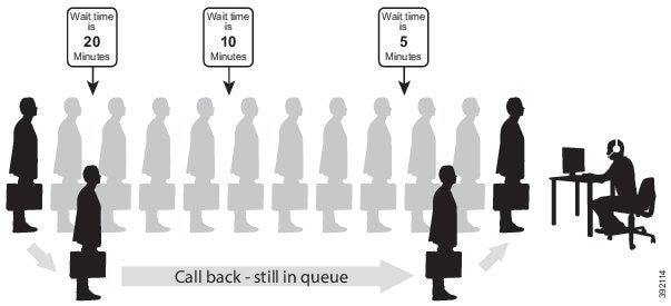
Call Context
Call Context refers to the attributes and data that are associated with a call.
Call Variables
You use call variables to pass business relevant data from Unified CVP to the agent desktop. Contact center enterprise solutions have a set of ten call variables. Each variable can contain 40 bytes of data.
Custom SIP Headers
With this feature, Unified CVP can pass selected SIP header information to and from Unified CCE for modification in the routing scripts. This feature gives you greater flexibility in providing SIP interoperability with third-party SIP trunks and gateways. You can pass information only in the header of the initial SIP INVITE, not for reinvites.
Be careful when modifying SIP headers. The tools do not check the syntax when you add or modify SIP headers.
Expanded Call Context Variables
Expanded Call Context (ECC) variables enable you to set business relevant data for transfer to the agent desktop. Unlike the call variables, you can configure the size, format, and the name of each ECC variable.
You can define as many ECC variables as necessary. But, you can only pass 2000 bytes of ECC variables on a specific interface at any one time. To aid you in organizing ECC variables for specific purposes, the solution has ECC payloads.
An ECC payload is a defined set of ECC variables with a maximum size of 2000 bytes. You can create ECC payloads to suit the necessary information for a given operation. You can include a specific ECC variable in multiple ECC payloads. The particular ECC variables in a given ECC payload are called its members.
You can use several ECC payloads in the same call flow, but only one ECC payload has scope at a given moment.
The solution includes an ECC payload named "Default" for backward compatibility. If your solution does not require more ECC variable space, you only need the Default payload. If your solution only has the Default payload, the solution automatically adds any new ECC variables to the Default payload until it reaches the 2000-byte limit.
User-to-User Information
User-to-user information (UUI) is the data that ISDN Supplementary Services provides as user-to-user services. UUI is an industry-standard field that enables info transfer between the contact center enterprise solutions and third-party solutions. The UUI feature transfers information between the calling and the called ISDN numbers during call setup and call disconnect.
In Unified CVP, you can use the UUI feature during transfers and disconnects to pass ISDN data from the PSTN to the Unified CCE router. You can also use UUI from Unified CCE to third-party ACDs.
The gateways can use application-specific UUI data in CTI applications and for better third-party ACD integration.
For example, you can pass data from an external system (such as caller-entered digits from a third-party VRU) to Unified CCE on an incoming call.
| Note | Unified CVP does not yet support the IETF UUI header. You can use the generic SIP header functionality to parse the standard UUI. |
Database Integration
You can integrate your contact center with an external database. Database integration provides create, update, and retrieve operations on tables in the external database. Database integration uses the Database Element in the CVP Call Studio.
Database Lookup
Database Lookup is an optional feature that allows you to read data from an external database and use that information within a routing script or administrative script.
Database Lookup is only supported by Packaged CCE 4000 agent and 12000 agent deployment.
For example, create a script that uses an external SQL database to lookup a caller's ANI and determine if the caller is a silver or gold customer.
You must designate a single key column as the SQL primary key. Use an If node to reference database columns accessed by the DB Lookup node. In this example, use the If node to determine if the caller is a silver or gold customer.
When the DB Lookup node is run, it attempts to query a row of data from the external database. If the node is run as a part of an admin script, it will be called at regular intervals to check for changes as scheduled. If the node is run as a part a routing script, it will be a database query from the DB Worker thread.
For details on how to create a database and use it in the script, see https://www.cisco.com/c/en/us/support/docs/customer-collaboration/unified-contact-center-enterprise/116215-configure-dblookup-00.html
| Note | If the external remote database is on SQL Server 2017 version, you have to install the ODBC Driver 17 manually on the server hosting the external database. Download the ODBC Driver 17 from Microsoft. |
Extension Mobility
To monitor and control the phones, the contact center solutions associate phones with a JTAPI user ID in Unified CM. When you use Extension Mobility or Extension Mobility Cross Cluster, you can associate an Extension Mobility device profile instead. In a Unified CCE environment, you associate the IP phones or the corresponding Extension Mobility device profiles with Unified CCE JTAPI user IDs. When an agent desktop signs in, the PIM requests a subscriber to allow the PIM to begin monitoring and controlling that phone. Until the agent signs in, the subscriber does not allow Unified CCE to monitor or control that phone. If the device or the corresponding Extension Mobility device profile is not associated with a Unified CCE JTAPI user ID, then the agent sign-in request fails.
Using Extension Mobility Cross Cluster (EMCC), when a Unified CCE PIM phone registers to the local cluster after Extension Mobility sign in, the phone looks like an agent situated across a WAN. The Unified CCE peripheral manages the agent devices based on the Extension Mobility profile rather than on a phone device in the Application User on the cluster. For more information, see the Cisco Collaboration System Solution Reference Network Designs at http://www.cisco.com/c/en/us/support/unified-communications/unified-communications-manager-callmanager/products-implementation-design-guides-list.html.
You can associate Extension Mobility devices using two methods; either by device or by user profile. Associate the Extension Mobility profile to the CCE Application User on Unified Communications Manager.
Configuring the EM Profile, instead of the device, provides more flexibility in which phones agents can use in the call center. Configuring the phone device limits which devices the agents can use. The option that you use in a contact center depends on the customer business case.
Mixed Codecs
By default, the contact center enterprise solutions accept incoming calls using the mu-law codecs. Your contact center can use the a-law codec instead. To use a-law, change the default values in CVP, Unified CM, and your VXML or Ingress Gateways. This table lists the audio codec support for various functions.
Table 2. Audio Codec Support
Function | Support |
|---|---|
Inbound calls | Both G.711 (mu-law and a-law) and G.729 codecs |
Outbound calls | G.711 (mu-law and a-law) only |
VRU | G.711 (mu-law and a-law) only |
Agents | Both G.711 (mu-law and a-law) and G.729 codecs |
| Note | In order to avoid transcoders and universal transcoders, use both G.711 and G.729 codecs for inbound calls and agents. Use G.729 as the first codec in your preference list to save bandwidth on the WAN. |
Cisco Outbound Option Dialer
SIP Dialers with CUBE can support a-law and u-law with specific design considerations.
Silent Monitor Support
The following silent monitoring solutions support both mu-law and a-law:
Unified CM-based Silent Monitoring
No Support for Mixed Environments
You cannot mix codec use between instances of the following elements:
All Mobile Agents on a peripheral are required to use the same codec.
All CVP prompts are required to use the same codec.
Mobile Agent
Mobile Agent enables an agent to sign in from anywhere with any PSTN phone and a broadband VPN connection for agent desktop communications. The agent functions just as an agent sitting in your contact center with a Cisco IP Phone. Mobile agent uses a pair of CTI ports which serve as proxies to connect the agent and the caller.
| Note | Mobile Agent cannot use IPv6-enabled CTI ports. |
Each PG can support fewer Mobile Agents than general agents. But, you can add extra PGs to support up to the maximum active agents that are allowed in the Reference Designs .
Phone Extension Support
Your contact center enterprise solution can support both general phone extensions and ACD (contact center) phone extensions. How you combine these types can affect your contact center.
You can assign phone lines to Unified CM clusters as follows:
You can mix general and ACD extensions in the same cluster.
You can separate the ACD extensions into specific clusters and the general extensions into other clusters.
You can also assign each agent's phone extensions to their device in several ways.
| Note |
|
Dual-Use Unified CM Clusters
You can use the same Unified CM cluster to support general IP telephony (office) extensions and ACD (contact center) extensions. However, consider the following points before choosing a dual-use cluster:
Contact centers have strict maintenance windows. Maintenance might affect office extensions at inopportune times.
Agents process far more calls than other office workers. Their devices place a higher load on the system than an average office worker. A cluster serving only office extensions can support many more extensions.
All devices are required to meet the compatibility requirements for the contact center solution. See your solution's Compatability Matrix.
Because of these points, separate clusters for each type of extension offer better performance.
Phone Extensions for Different User Types
You can assign extensions differently to each agent's device to match their needs.
Unified CCE supports only one agent ACD extension on the IP phone. To enable Unified CCE to manage and control all calls on that extension, it cannot have voice-mail or call forwarding defined. Typically, the agent extension is not used as the agent’s office extension. You can assign a separate extension to the agent’s phone for that purpose. The office extension can have voice-mail and other calling features.
Typically, the connection defaults to the first extension on an IP phone when you pick up the handset. You want that first extension assigned to the extension that each person uses most often. Consider the following configurations based on the person's duties:
Contact Center Agent—Assign the agent's ACD extension to the first position and their office extension to another position. This layout makes answering inbound ACD calls easiest. The contact center tracks any calls the agent places on the ACD extension as external calls. When the agent places a call on that extension, Unified CCE puts the agent in not-ready mode and does not route calls to that agent.
Knowledge Worker—These agents don't directly handle many ACD calls. Assign their office extension to the first position and their ACD extension to another position. This layout avoids the contact center tracking their non-ACD calls. Because these agents place most calls on their office extensions, they must manually set their state to not-ready mode for most calls. That mode prevents Unified CCE from routing ACD calls to them during that time.
Single-line Worker—These agents use the same extension for their ACD and office calls. This option enables you to see all agent activity and to avoid all interruptions for the agent. However, this option requires special care in your routing scripts to prevent agent-to-agent calls from interrupting customer calls. The routing employs CTI Route Points and a unique DN for each CTI Route Point.
Back-Office Agents—These agents typically only use their office extension. Assign their office extension to the first position. If a back-office agent occasionally handles ACD calls, assign their ACD extension to the last position on their IP phone.
Post Call Survey
A Post Call Survey takes place after the call. Typically, you use the survey to determine whether a customer was satisfied with the call experience. You configure a call flow that sends the call to a DNIS for the Post Call Survey after the agent disconnects from the caller.
Your VRU asks callers whether they want to participate in a Post Call Survey. If they choose to do so, they are automatically transferred to the Post Call Survey after the call flow completes.
Cisco Webex Experience Management
Cisco Webex Experience Management is the platform for Customer Experience Management (CEM), integrated with powerful tools that allow you to see your business from your customers' perspective. Experience Management has all the sophisticated features and functionality including customer journey mapping.
With Experience Management integrated with Packaged CCE:
Administrators can configure post call surveys to collect feedback directly from customers.
Administrators can configure analytical gadgets, which can be viewed on Finesse desktop.
Agents and supervisors can view pulse of the customers through industry standard metrics such as NPS, CSAT, and CES or other KPIs.
| Note | Currently, you can have surveys only for inbound ICD calls. |
For information on how to configure Experience Management, see the Webex Experience Management chapter in the Cisco Unified Contact Center Enterprise Features Guide at https://www.cisco.com/c/en/us/td/docs/voice_ip_comm/cust_contact/contact_center/icm_enterprise/icm_enterprise_12_0_1/Configuration/Guide/ucce_b_ucce-features-guide-12.html
Precision Routing
Precision Routing is a routing feature in Unified CCE. Precision Routing enhances and can replace traditional routing.
Traditional routing maps all an agent's skills into a hierarchy of business needs. However, traditional routing is restricted by its single dimensional nature. Precision Routing provides multidimensional routing with simple configuration, scripting, and reporting. The feature records varying proficiencies in a skill, rather than just possession of the skill. These multiple attributes with proficiencies more accurately expose the capabilities of each agent. The greater accuracy in routing brings more value to the business.
You can use a combination of attributes to create multidimensional precision queues. Unified CCE scripting can dynamically map the precision queues to match a caller's needs with the best available agent.
For more information on Precision Routing, see the Cisco Unified Contact Center Enterprise Features Guide at http://www.cisco.com/c/en/us/support/customer-collaboration/unified-contact-center-enterprise/products-feature-guides-list.html.
Single Sign-on (SSO)
The Single Sign-on (SSO) feature authenticates and authorizes agent and supervisor access to the contact center solution applications and services. The authentication process validates the identity of a user: "you are who you say you are." The authorization process confirms that an authenticated user is permitted to perform the requested action: "you can do what you are asking to do." When you enable SSO in the contact center solution, users only sign in once to gain access to all their Cisco browser-based applications and services. Access to Cisco administrator applications is not available through SSO.
SSO requires the following:
A third-party Identity Provider (IdP)
A Cisco Identity Service ( Cisco IdS ) cluster
When an SSO-enabled user signs in, the Cisco IdS interacts first with your IdP to authenticate the user. When the user is authenticated, the Cisco IdS confirms with the accessed Cisco services to confirm that the user is authorized for the requested role. When the user is both authenticated and authorized, the Cisco IdS issues an access token that allows the user to access the application. The access token enables the user to switch between the authorized contact center applications for that session without presenting credentials again.
- SAML 2.0 Authentication
- Elements Used in SAML 2.0
- Cisco Identity Service (IdS)
- Authentication and Authorization Flow
SAML 2.0 Authentication
SSO uses Security Assertion Markup Language (SAML) to exchange authentication details between an Identity Provider (IdP) and a service provider. The identity provider authenticates user credentials and issues SAML assertions, which are pieces of security information transferred from the identity provider to the service provider for user authentication. Each assertion is an XML document that contains trusted statements about a subject including, for example, username and privileges. SAML assertions are usually digitally signed to ensure their authenticity.
A generic SAML authentication flow consists of:
Client - A browser-based user client used to access a service.
Service Provider - An application or service the user tries accessing.
Identity Provider - An entity performing the user authentication.
The identity provider keeps actual credentials and authentication mechanism hidden. Based on the authentication process result, the identity provider issues SAML assertions.
Elements Used in SAML 2.0
The following is the list of elements that are used in SSO SAML 2.0 authentication:
Client (the user’s client)—A browser-based client or a client that can leverage a browser instance for authentication. For example, a system administrator’s browser.
Lightweight Directory Access Protocol (LDAP) users—Users are integrated with an LDAP directory. For example, Microsoft Active Directory or OpenLDAP.
Security Assertion Markup Language (SAML) assertion—An assertion is an XML document that contains trusted statements about a subject. For example, a username. SAML assertions are digitally signed to ensure their authenticity. It consists of pieces of security information that are transferred from Identity Providers (IdPs) to the service provider for user authentication.
Service Provider (SP)—An application or service that trusts the SAML assertion and relies on the IdP to authenticate the users. For example, Cisco Identity Service (IdS).
An Identity Provider (IdP) server—This is the entity that authenticates user credentials and issues SAML assertions.
SAML Request—An authentication request that is generated by a Cisco Identity Service (IdS). To authenticate the LDAP user, IdS delegates an authentication request to the IdP.
Circle of Trust (Co-T)—It consists of the various service providers that share and authenticate against one IdP in common.
Metadata—An XML file generated by the Cisco IdS (for example, Cisco Identity Service Management) and an IdP. The exchange of SAML metadata builds a trust relationship between the IdP and the service provider.
Assertion Consumer Service (ACS) URL—A URL that instructs the IdPs where to post SAML assertions.
Cisco Identity Service (IdS)
Authentication is managed for the contact center solution by the Cisco Identity Service (Cisco IdS). When an SSO-enabled user signs in, the Cisco IdS interacts first with the customer's Identity Provider (IdP) to authenticate the user. The IdP stores user profiles and provides authentication services to support SSO sign-ins. When the user is authenticated, the Cisco IdS exchanges information with the Cisco service the user is attempting to access to confirm that the user is authorized for the role they are requesting. When the user is both authenticated and authorized, the IdS issues an access token that allows the user to access the application. When the access is established during a particular session, the user can switch among contact center solution applications without presenting credentials again.
Authentication and Authorization Flow
The complete authentication and authorization flow has been simplified as:
When you access an application with protected resources, the application will redirect you to the Cisco Identity Service for authentication. Cisco Identity Service leverages SAML and generates a SAMLRequest and redirects the browser to the Identity Provider.
The browser authenticates directly against the Identity Provider. Applications are not involved in the authentication process and have no access to user credentials.
The OAuth flow accesses the resource with a token which is then validated.
Cisco Identity Service sends an authentication request through the browser to the identity provider.
The user enters the login credentials to the identity provider for authentication. After the assertion is successful and the user attributes are read it will redirect to the original application that was accessed. Cisco Identity Service accompanied by an assertion that confirms successful authentication and includes user information and access rights for the web application.
Figure 25. Authentication and Authorization Flow
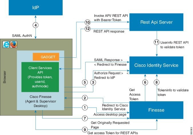
Whisper Announcement
Whisper Announcement plays a brief, prerecorded message to an agent just before the agent connects with each caller. The announcement plays only to the agent; the caller hears ringing while the announcement plays.
The announcement can contain information about the caller that helps prepare the agent to handle the call. The information can include caller language preference, choices the caller made from a menu (Sales, Service), customer status (Platinum, Gold, Regular), and so on.
After you enable Whisper Announcement, you specify which announcements to play in the call routing scripts. The script chooses which announcement to play based on various inputs. For example, different scripts might play for different dialed numbers, customer ID lookups in your customer database, or selections the caller made from a VRU menu.
Call Flows
Reference designs only supports Unified CVP comprehensive call flows. The comprehensive call flow includes VRU, queuing, and IP switching.
Figure 26. Logical Component Connectivity
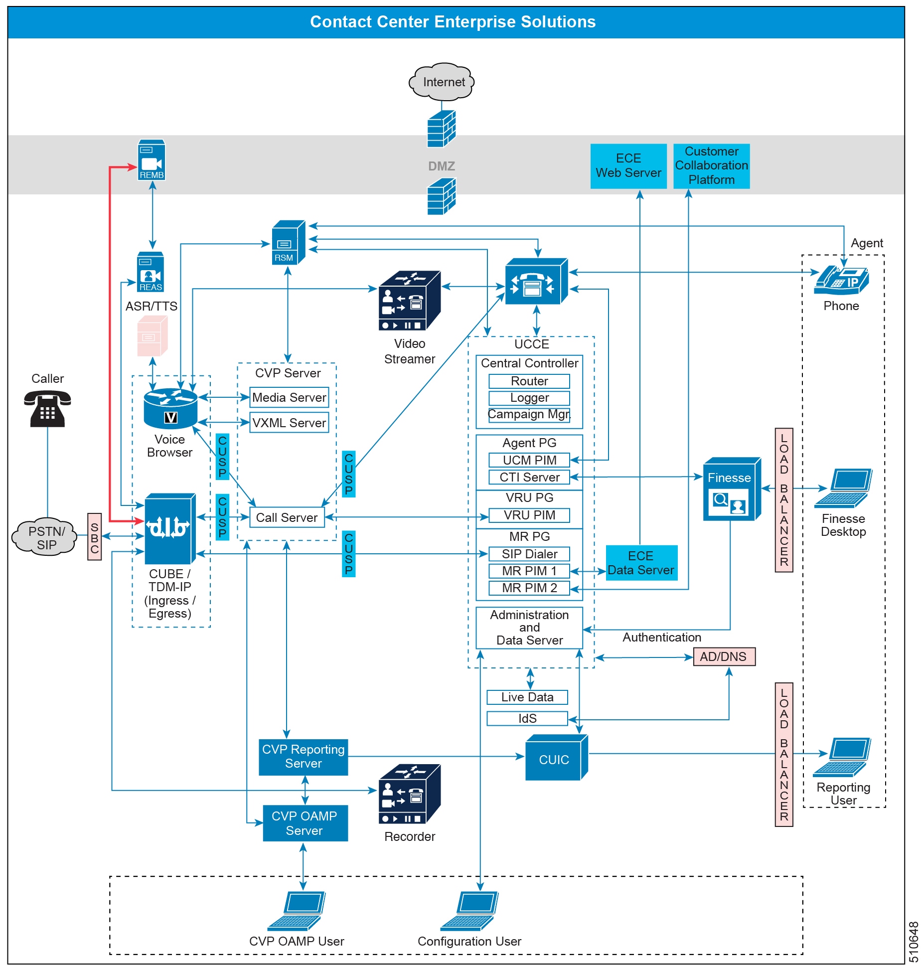
Comprehensive
The Comprehensive call flow can route and transfer calls across your VoIP network. For example, you can use this model to offer VRU services, and to queue calls for routing to an agent. Callers reach a VRU initially. If they need help from an agent, their call receives queue treatment and transfers to an agent. You can also transfer calls between agents. Unified CVP and Unified CCE pass call data between these endpoints and provide reporting for all calls.
The Comprehensive call flow has the following features:
Allows callers to access the contact center through local, long distance, or toll-free numbers terminating at the ingress voice gateways, and from VoIP endpoints.
Provides VRU, including integrated self-service applications, queuing, and initial prompt and collect, and IP switching capabilities.
Can route and queue calls to Unified CCE agents.
Must use SIP.
Provides the video VRU, video queuing, and video agent capabilities.
Use an optional Unified CVP VXML Server.
Prompt or collect data using optional ASR and TTS services.
- Incoming Calls
- Comprehensive with ICM Micro-Apps or CVP Call Studio Apps
- Video Call Flow
- Supplementary Services
Incoming Calls
Incoming calls can come from an outside carrier (either SIP or TDM) or an internal help desk. Congestion Control counts incoming calls against your CPS.
| Note | All new incoming calls always enter the Cisco IOS gateway (CUBE or TDM-IP gateway) and are associated with the Unified CVP survivability service. |
Incoming Calls from Carrier
The following table shows the basic SIP trunk or TDM-IP GW call flow.
| Call Flow | Logical Call Routing | ||
|---|---|---|---|
Incoming call from Carrier | VRU: Caller --> Carrier --> CUBE or TDM-IP GW--> Unified CVP --> Voice Browser Agent: Caller --> Carrier --> CUBE or TDM-IP GW--> Unified CVP -->Unified Communications Manager -> Agent 1
|
The call flows in the following figure represent units of call flow functionality. You can combine these call flow units in any order during a call.
Figure 27. Basic Call Flow with VRU and Queue to an Agent
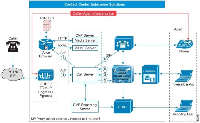
The call flow for an incoming call from the Carrier to a TDM Gateway or through the SBC to the CUBE gateway is as follows:
New incoming call from CUBE or TDM gateway to CVP.
New incoming call to Unified CCE from CVP.
Play "Hello World" Prompt.
CVP sends call to Voice Browser, and the caller hears the VRU.
When an agent is available, Unified CCE sends the agent number to CVP.
CVP sends the call to the agent phone through Unified CM.
Incoming Calls from Internal Help Desk
Enterprises that use IP phones can provide their employees with call-in self-service applications, for example, an application to sign up for health benefits. An employee might try to reach an agent, such as the IT help desk, and end up waiting in queue. Both of these scenarios result in calls originating from Unified CM to Unified CVP through CUBE.
| Call Flow | Logical Call Routing |
|---|---|
Incoming call from Unified Communications Manager (internal help desk) | VRU: Caller --> Unified CM --> CUBE(E) --> Unified CVP --> Voice Browser Agent: Caller --> Unified CM --> CUBE(E) --> Unified CVP --> Unified CM -> Agent1 |
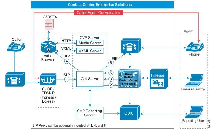
| Note | You can optionally insert the Cisco Unified SIP Proxy between the following core components:
|
Comprehensive with ICM Micro-Apps or CVP Call Studio Apps
When you use Micro-Applications or Call Studio applications, the call flow is as follows:
Figure 29. Detailed Call Flow for New Incoming Call
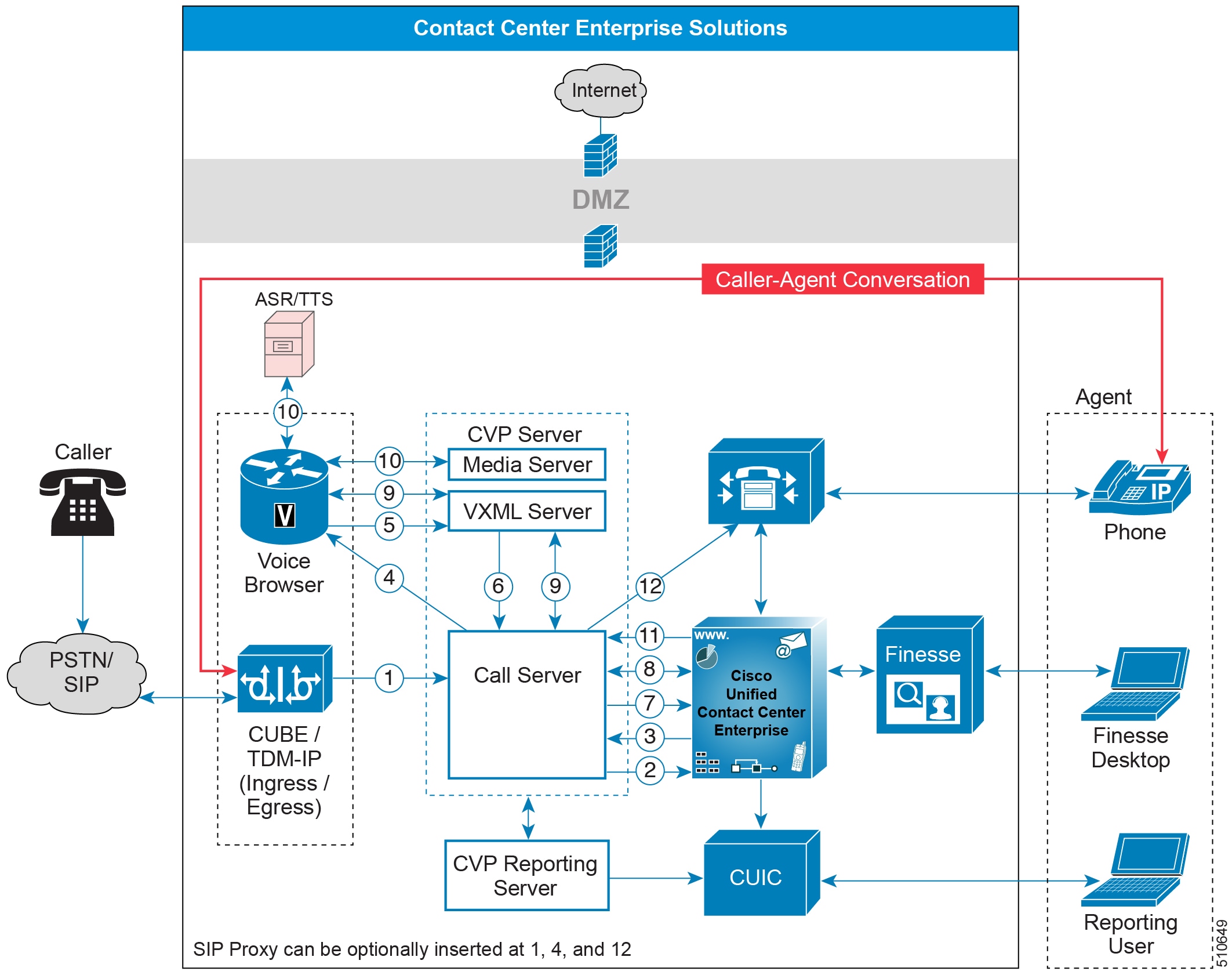
The new incoming call comes into a CUBE or a TDM-IP Gateway.
New incoming call to Unified CCE from CVP. The CVP Call Server sends a route request to Unified CCE through VRU PG. This route request for a DN invokes Unified CCE to run a routing script based on the DN and call type association.
The Unified CCE routing script uses either an implicit or explicit
Send to VRUnode to return a label to CVP Call Server. There is a pause in the script being run .The label is a combination of the configured network VRU label for CVP and a random correlation id.
The CVP Call Server sends an SIP Invite message to the Voice Browser by translating the network VRU label to the browser's IP address. Optionally, this can pass through a SIP Proxy Server.
The Voice Browser sends an HTTP New Call message to the VXML Server with the network VRU label.
The VXML Server then sends the request to Call Server.
CVP Call Server then sends a request instruction message to Unified CCE, which then resumes the routing script.
The Unified CCE routing script uses
Run Scriptnodes to instruct the CVP Call Server about the VRU treatment.Unified CCE can then send a
Run Script
              Request
message to run a VRU operation. The request can invoke the following:Micro-Application—Use a Micro-Application for simple VRU operations. It supports basic operations like playing prompts and collecting digits. The Micro-Application is referenced in the Unified CCE Script and defined as part of a network VRU script.
Call Studio Application—Use a Call Studio Application for complex VRU call flows. You design it in the Call Studio Designer and deploy it in the VXML Server. You can then reference the application in a Unified CCE script.
The Call Server communicates with the VXML Server to invoke the specific application.
Based on the Micro-Application or Studio Application, VXML Server generates the relevant VXML page. The Voice Browser renders the page to the caller. The VXML Server and Voice Browser communicate back and forth with each other until the end of the application.
The Voice Browser connects to one of the following services during the rendering of the VXML page:
For audio prompts, it connects over HTTP to the Media Server, which is coresident on the CVP Server.
For ASR/TTS, it establishes an MRCP connection with an external speech server to synthesize the text prompt or recognize a user speech for user input.
For video, it connects over SIP to an external server to play a video prompt.
Note
If there are any more applications to run, the call flow repeats Steps 8-10.
When an agent is available, Unified CCE sends the agent number to CVP. The VRU initiation stops once the Unified CCE script gets a Queuing node or Release node in the script. The SIP call leg with the Voice Browser terminates.
CVP sends the call to the agent phone through Unified CM.
Video Call Flow
This call flow runs through a video VRU before connecting to an agent.
Figure 30. Video Call Flow
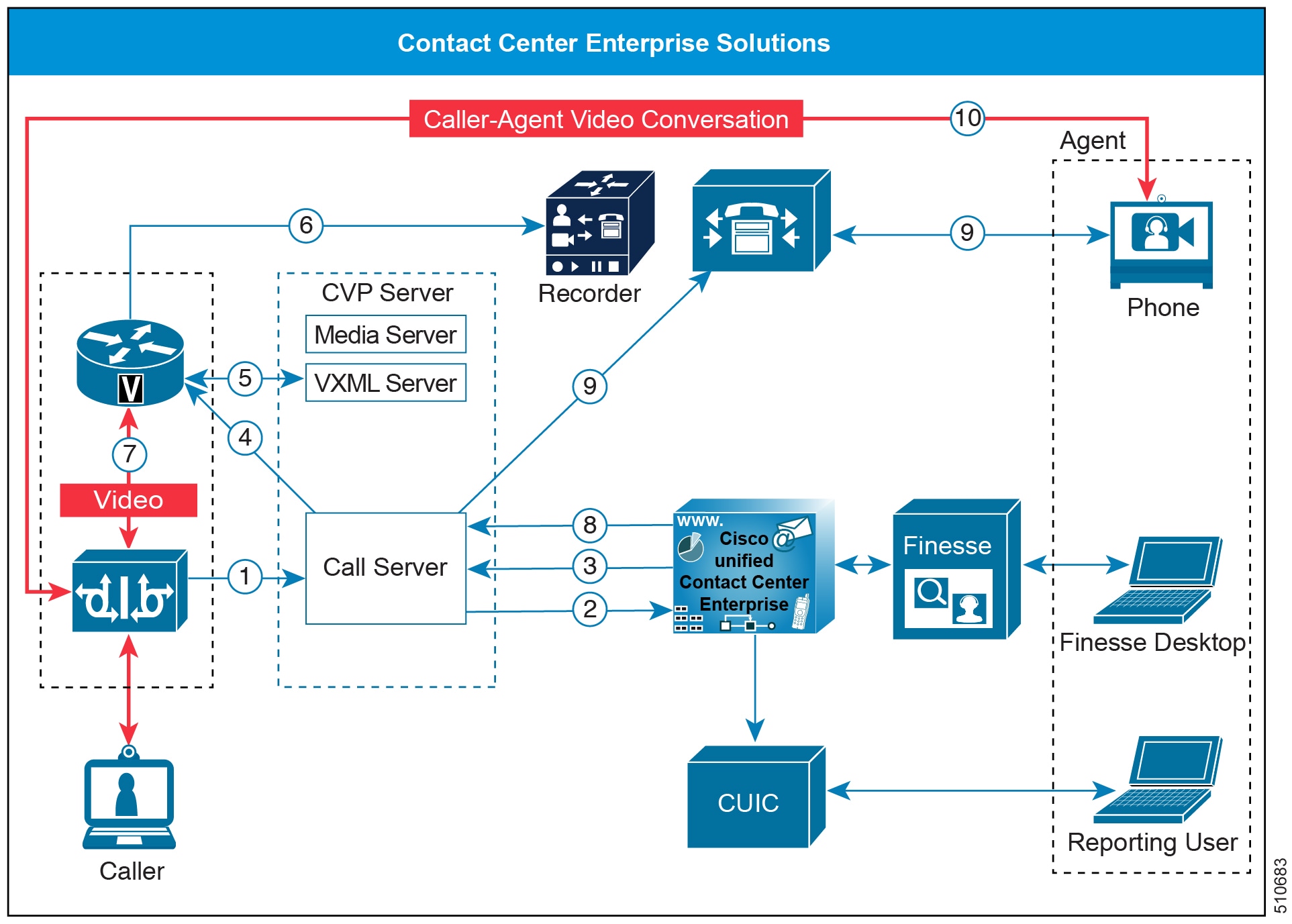
Send a incoming call from Unified CM to CVP.
Send a incoming call from CVP to Unified CCE.
Play the CVP Studio video application.
CVP sends the call to CUBE and the VXML gateway.
CVP VXML Server instructs the VXML gateway to connect to DN XXXX.
CUBE sends the call to the Video Media Server with DN XXXX. Caller gets static video.
Agent is now available.
CVP sends the call to and agent.
Supplementary Services
Supplementary services include the following call flows:
Table 3. Supported System Call Flows
| System Call Flows | Supported |
|---|---|
Hold and Resume | Yes |
Consult Transfer and Conferences | Yes |
Blind Transfer and Conferences | Yes |
Router requery | Yes |
Postroute using Unified CVP | Yes |
Hold and Resume
Agents use Hold to suspend a call temporarily. If Music on Hold resources are available, the caller hears music while on hold. Otherwise, the caller hears a tone.
Multicast Music-on-Hold
As an alternative to the unicast Music-on-Hold (MOH), you can multicast MOH with supplementary services on Unified CM. You have these options when deploying MOH with this feature:
With Unified CM multicasting the packets on the local LAN
With the branch gateway multicasting on their local LAN
Use branch gateway multicasting when you have configured survivable remote site telephony (SRST) on the gateway. This method enables the deployment to use MOH locally and avoid MOH streaming over the WAN link.
| Note | For information about configuring MOH on the Call Manager Enterprise (CME), see https://www.cisco.com/c/en/us/td/docs/voice_ip_comm/cucme/admin/configuration/manual/cmeadm/cmemoh.html#wpmkr1022205. |
Transfers and Conferences
In most contact center solutions, agents can transfer calls to or start conferences with other agents. There are two ways to transfer or start a conference:
Blind
Consult (also known as a warm transfer)
Blind Transfers and Conferences
In a blind transfer, the first agent dials a number and ends the call. The caller then gets connected to the second agent or placed into a queue if necessary. This type of transfer does not involve a call originated by Unified CM.
Figure 31. Blind Transfer Call Flow with VRU and Queue to a Second Agent
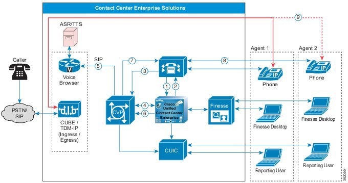
Agent 1 begins a blind transfer request, an incoming call form Unified CM to Unified CCE.
Agent 2 is unavailable, which sends the call to the VRU.
Unified CM sends the call to Unified CVP.
Unified CCE instructs CVP to connect to the Voice Browser to play VRU or queue music.
Unified CVP sends the call to the Voice Browser. The caller hears the VRU or queue music.
When Agent 2 is available, Unified CCE sends the agent number to CVP.
Unified CVP sends a SIP call to Agent 2 through Unified CM. The VRU or queue music disconnects.
Unified CM sends the call to Agent 2 and the call data appears on the Cisco Finesse desktop.
The caller talks to Agent 2.
Consult Transfers and Conferences
In a warm transfer or conference, the agent dials a number and is connected to the second agent while the caller is placed on hold. The two agents can talk, then they can conference in the caller, and the first agent drops off. If the second agent is not available, the first agent (not the caller) is placed into a queue. All of this processing can take place without involving Unified CVP, unless the first agent gets queued. In that case, the first agent's call is transferred to Unified CVP, which creates a call originated by Unified CM.
Table 4. SIP Trunk Call Flow
| Call Flow | Logical Call Routing |
|---|---|
| Post routed call from agent-to-agent | VRU: Agent 1 --> Unified CM --> Unified CVP --> Voice Browser Agent: Agent 1 --> Unified CM --> Unified CVP --> Unified CM--> Agent 2 |
Figure 32. Consult Call Flow with VRU and Queue to a Second Agent
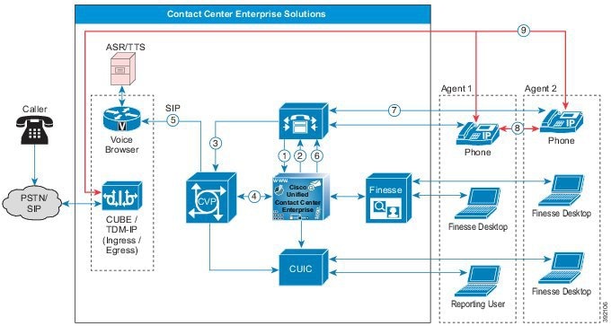
Agent 1 begins a consult transfer request, an incoming call from Unified CM to Unified CCE.
Agent 2 is unavailable, which sends the call to the VRU.
Unified CM sends the call to Unified CVP.
Unified CCE instructs CVP to connect to the Voice Browser to play VRU or queue music.
While Agent 1 waits, they get treated with the VRU. The agent hears the VRU or queue music and the caller gets the Music on Hold (MOH).
When Agent 2 is available, Unified CCE sends the agent number to Unified CM.
Unified CM sends a SIP calls to Agent 2. The VRU disconnects.
Agent 1 consults with Agent 2.
Agent 1 completes the transfer. The caller speaks with Agent 2 and Agent 1 drops off.
| Note | Conference call flows are the same as consult call flows. Both conference call flows and consult call flows conference the call with the agents, rather than holding them during consult. Hold and Resume, Alternate and Reconnect, and Consult and Conference call flows invoke the session initiation protocol (SIP) ReINVITE procedure to move the media streams. A Conference to VRU call flow is similar to conference with no agent available call flow. |
SIP Refer Transfer
In some scenarios, Unified CVP transfers a call to a SIP destination and does not have Unified ICM and Unified CVP retain any ability for further call control. Unified CVP can perform a SIP Refer transfer, which allows Unified CVP to remove itself from the call, and free licensed Unified CVP ports. The Ingress Voice Gateway port remains in use until the caller or the terminating equipment releases the call. SIP Refer transfers are used in both Comprehensive and Call Director deployments.
Invoke a SIP Refer transfer by any of the following methods:
Unified ICM sends Unified CVP a routing label with a format of rfXXXX (For example, rf5551000).
An application-controlled alternative is to set an ECC variable (user.sip.refertransfer) to the value y in the Unified ICM script, and then sends that variable to Unified CVP.
Note
Direct Refer transfer using label works only if Send To VRU node is used before the Refer.
You can invoke the SIP Refer transfer after Unified CVP queue treatment has been provided to a caller. SIP Refer transfers can be made to Cisco Unified Communications Manager or other SIP endpoints, such as a SIP-enabled ACD.
Router requery on a failed SIP Refer transfer is supported using SIP with the Unified CVP, but only on calls where the survivability service is not handling the SIP Refer request.
Network Transfer
Unified CVP allows Network Transfer to transfer calls to another destination after an agent answers them.
There are two flags in Unified ICM to control the Network Transfer:
NetworkTransferEnabled—This flag is part of the Unified ICM script. When enabled, it instructs the Unified ICM to save the information about the initial routing client (the routing client that sent the NewCall route request).
NetworkTransferPreferred—This flag is enabled on the Unified CVP Peripheral Gateway configuration. When enabled, any route request from this routing client sends the route response to the initial routing client instead of the routing client that sent the route request.
The following points explain how you can do a network transfer:
You can use Network Transfer to perform a blind transfer only from agent 1 to agent 2 through Unified CVP. In this case, Unified CCE instructs Unified CVP to route the contact back from Agent 1, and then route it either to a Voice Browser (for VRU treatment) or to another destination (for example, to Agent 2).
You cannot use Network Transfer to perform a warm transfer or conference with Unified CVP. The call leg to Agent 1 must be active while Agent 1 performs a consultation or conference. Unified CVP cannot route the contact back from Agent 1 during the warm transfer or conference.
If a caller dials the same number regardless of a blind transfer, warm transfer, or conference, then perform the following tasks:
Do not enable the NetworkTransferEnable flag in the Unified ICM script.
Dial the CTI Route Point of the same Unified CCE Peripheral Gateway for any transfer or conference request to preserve the call context during the transfer. Dialing the Route Pattern or CTI Route Point of another Peripheral Gateway does not preserve the call context.
Use SendToVru as the first node in the Unified ICM routing script.
| Note | Extra ports are used during the consultation, blind transfer, or conference calls. They are released after the originating consultation is terminated. |
Requery and Survivability
Router requery allows the rerouting of calls due to any network failure connections. For example, Ring No Answer, Busy, and Network Unreachable trigger router requery. Only the QUEUE node and Label node in Unified CCE scripts support router requery. Define the rerouting logic in the script based on the error path from these nodes.
Call survivability on CVP runs on the ingress gateway. It triggers the survivability action when CVP detects any downstream failures. Based on the routing parameters for the survivability, you can have a failure trigger actions like a call restart or sending the calls to the local SRST phones.
Topologies
Cisco Unified Contact Center Enterprise (Unified CCE) is a solution that delivers intelligent call routing, network-to-desktop Computer Telephony Integration (CTI), and multichannel contact management over an IP network to contact center agents. Unified CCE adds software to create an IP automatic call distribution (ACD) onto a Cisco Unified Communications framework. This unified solution allows companies to rapidly deploy an advanced, distributed contact center infrastructure.
You can configure Unified CCE to sort customer contacts. Unified CCE monitors resource availability and delivers each contact to the most appropriate resource in the enterprise. The system profiles each customer contact using related data such as dialed number and calling line ID, caller-entered digits, data submitted on a web form, and information obtained from a customer database lookup. Simultaneously, the system monitors the resources available in the contact center to meet customer needs, including agent skills and availability, voice-response-unit (VRU) status, and queue lengths.
Unified CCE allows you to smoothly integrate inbound and outbound voice applications with internet applications such as real-time chat, web collaboration, and email. This integration enables a single agent to support multiple interactions simultaneously regardless of which communications channel the customer chooses.
The Unified CCE base model includes a common set of features that apply across supported Unified CCE models.
- Contact Center Enterprise Architecture
- Topology Types
- Centralized Deployments
- Distributed Deployments
- Global Deployments
- Remote Office Options
Contact Center Enterprise Architecture
The following figure shows the logical view of the contact center enterprise topology. Agents that are local to the site are not shown.
Figure 33. Contact Center Enterprise Solution Topology and Remote Office Options

Topology Types
There are three topology models for contact center enterprise solutions:
Centralized Deployments—Servers colocated in single main site
Distributed Deployments—Servers distributed across different geographic sites
Global Deployments—Remote Peripheral Gateway (PG) and peripheral
Figure 34. Topologies
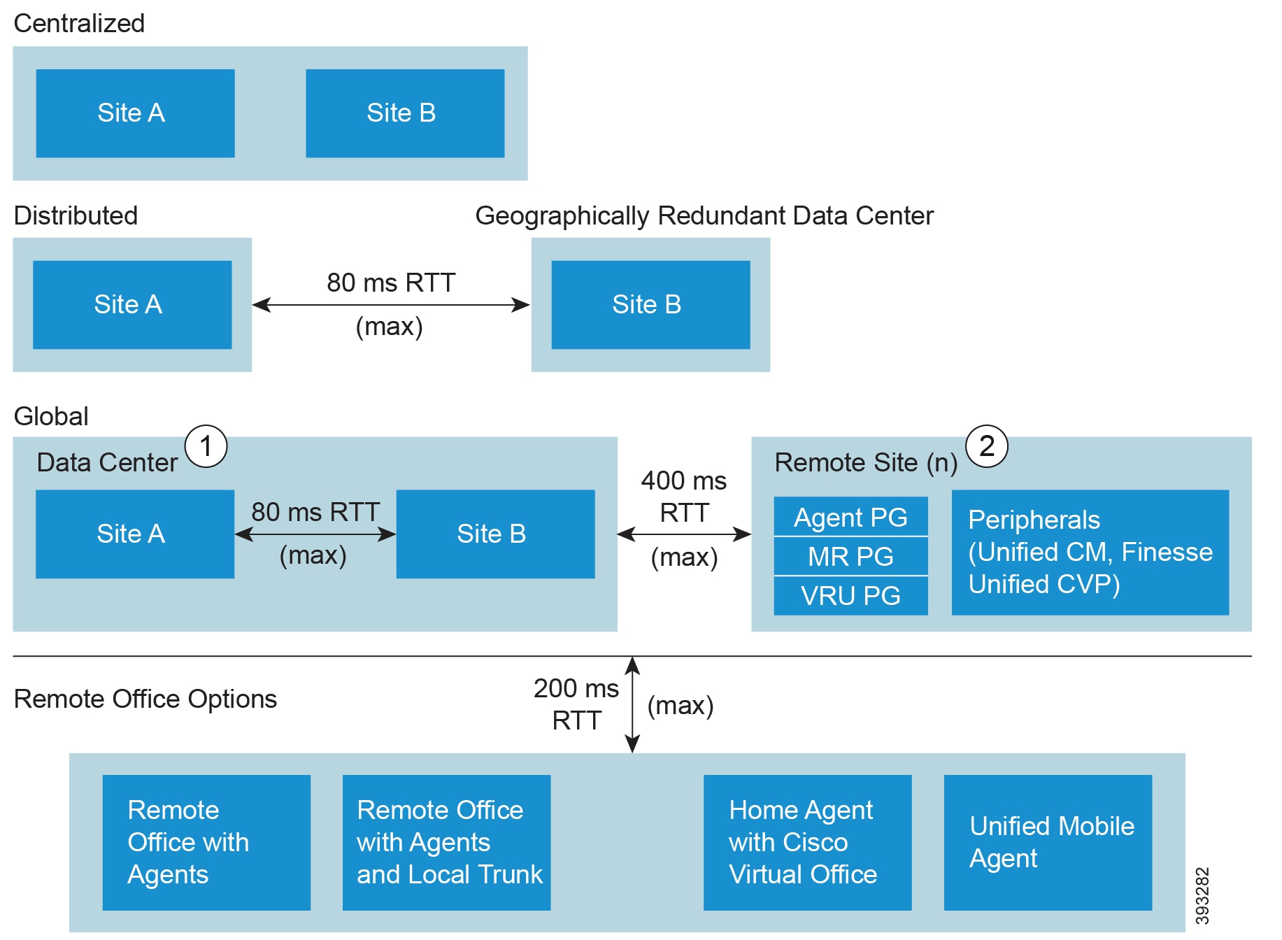
| Note |
|
Centralized Deployments
A centralized site can contain all the Unified CCE base model components. In a centralized data center, the agents, supervisors, and administrators are local to the data center. A centralized site can also include multiple agent locations.
In the local agent deployment scenario, the agents, supervisors, and administrators are local to the site.
Local Agent Architecture
The following figure shows the physical view of a local agent.
Figure 35. Local Agent—Physical View
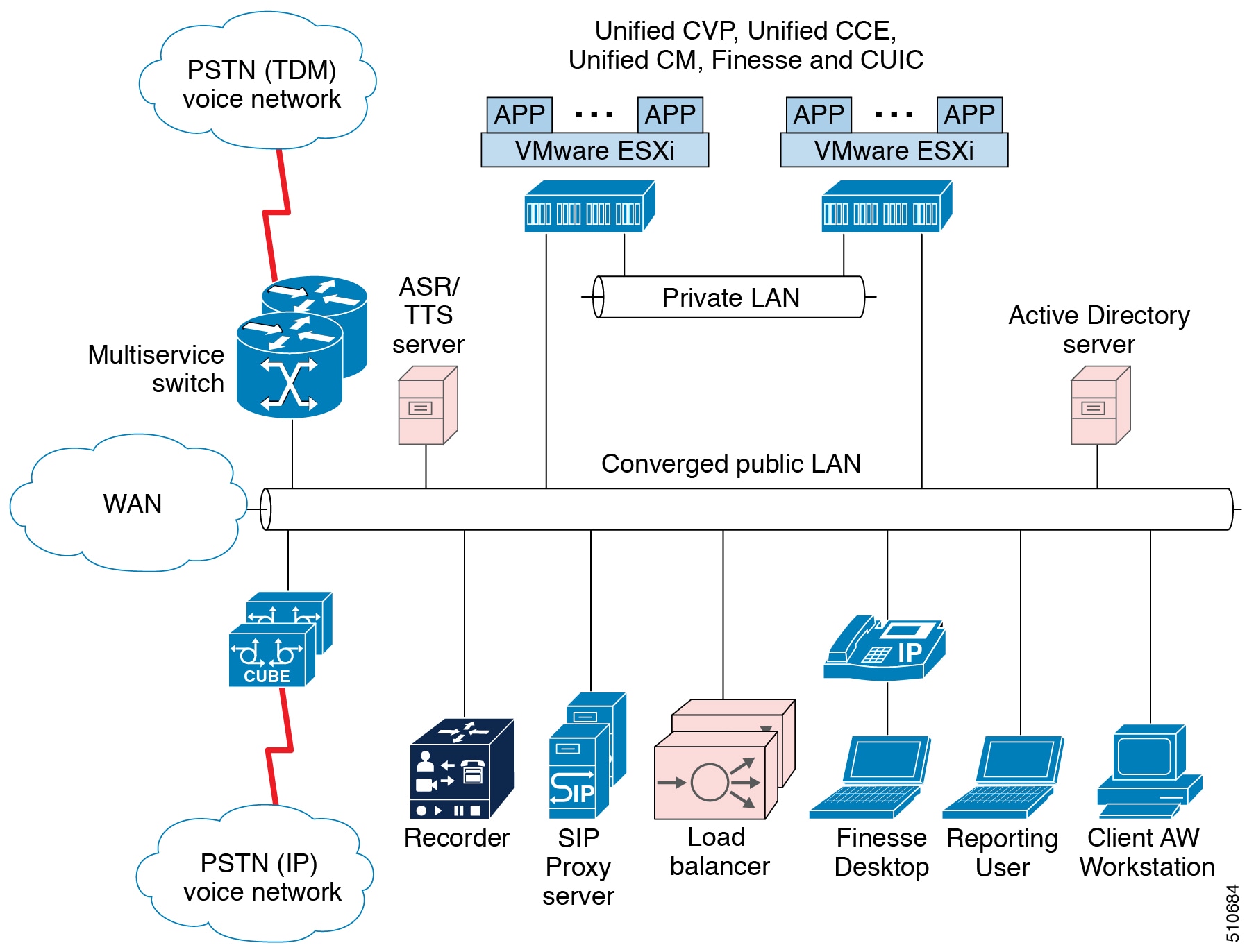
Local Agent Components
The local agent deployment scenario includes the following components in addition to the core solution components:
Unified Intelligence Center browser clients for local access to reporting
Administration tools, such as, Unified CCE configuration tools, Internet Script Editor, or the local Administrative Workstation
Optional third-party recording server for VoIP capture of agent or customer calls
Agent phones with Built-In Bridge (BIB) to support features like Silent Monitoring.
Local Agent Benefits
The local agent deployment scenario provides the following benefits:
Does not require location-based call admission control
Simple codec setup
Local Agent Design Requirements
The following table describes the design requirements for a local agent.
Table 5. Local Agent Design Requirements
| Requirement | Notes | |
|---|---|---|
| Infrastructure | Location-based call admission control is not required | Local agents use LAN bandwidth, which is typically sufficient for all Unified CCE traffic. |
| Desktop | Cisco Finesse Customer Relationship Management | |
| Codec | Transcoding is not required. | If all agents are local to the data center (no required WAN connectivity), you do not need to use G.729 or any other compressed RTP stream. |
| Recording | Unified CM-based BIB Unified CM Network Based Recording with Cisco Unified Border Element and the recorder. The Unified CM NBR feature allows for setting preference and fallback of CM controller media-forking at the originating Cisco Unified Border Element or the IP Phone's BIB. | By default, you can only record all agents constantly. Selective recording requires extra integration work. |
| Silent Monitoring | Unified CM-based BIB |
The following table describes the media resources for a local agent.
Table 6. Local Agent Media Resources
| Resource | Method | Notes |
|---|---|---|
Music on Hold | Unicast Unified Communications Manager | |
Conference bridges | IP phone with BIB Hardware-based, located at voice gateways | |
Media Termination Points | Not supported | |
Transcoders | Hardware-based, located at voice gateways | Required for SIP trunks with a-law. |
Distributed Deployments
Globalization, security, and disaster recovery considerations are driving business to diversify locations across multiple regions. In addition, organizations want to distribute workloads between servers, share network resources effectively, and increase the availability of critical applications. Geographically redundant sites split critical applications across two data centers. Enterprises deploy geographically redundant sites to minimize planned or unplanned downtime and share data across regions.
Geographically redundant sites have a load balancer in each data center.
Clustering Over the WAN
The following figure shows geographically redundant sites with clustering over the WAN.
Figure 36. Geographically Redundant Sites with Clustering over WAN
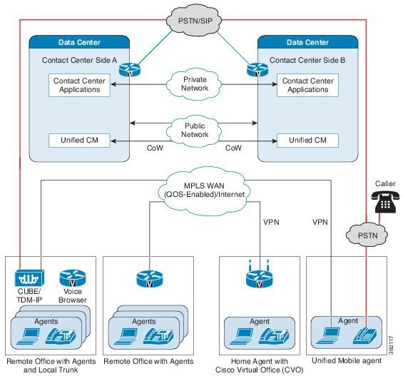
Geographically redundant sites provide clustering over the WAN, distributed Unified Communications Manager clusters, and 1:1 redundancy for Unified CVP, SIP proxy, voice gateways, and Cisco Unified Intelligence Center.
Latency requirements across the high-availability (HA) WAN must meet the current Cisco Unified Communications requirements for clustering over the WAN. Unified CM allows a maximum latency of 40 ms one way (80-ms round trip).
Keep the public and private traffic on separate routes within the network and respect standard latency and bandwidth. Use independent physical circuits for the public and the private traffic.
Global Deployments
Global Deployments enable the Service Provider to deploy a single contact center available worldwide with a centralized main site and global access. This reduces deployment costs by eliminating multiple customer instances.
You can locate the Unified CM in a centralized or remote site or a customer premise. The following global deployment topologies are supported:
Remote CVP deployment
Remote Unified CM deployment
Remote CVP and Unified CM deployment
Remote MR PG deployment with multichannel options
Remote CVP Deployment
The topology shown in the illustration shows a simple example of Remote CVP deployment. In certain cases, contact center enterprise solutions use this topology for widely distributed sites. This topology provides global access to a centralized main site. This deployment requires extra Unified CVP servers with Unified CCE VRU PG Servers at remote sites. The maximum RTT with the central controller over the WAN is 400 ms.
Figure 37. Remote CVP Deployment Topology
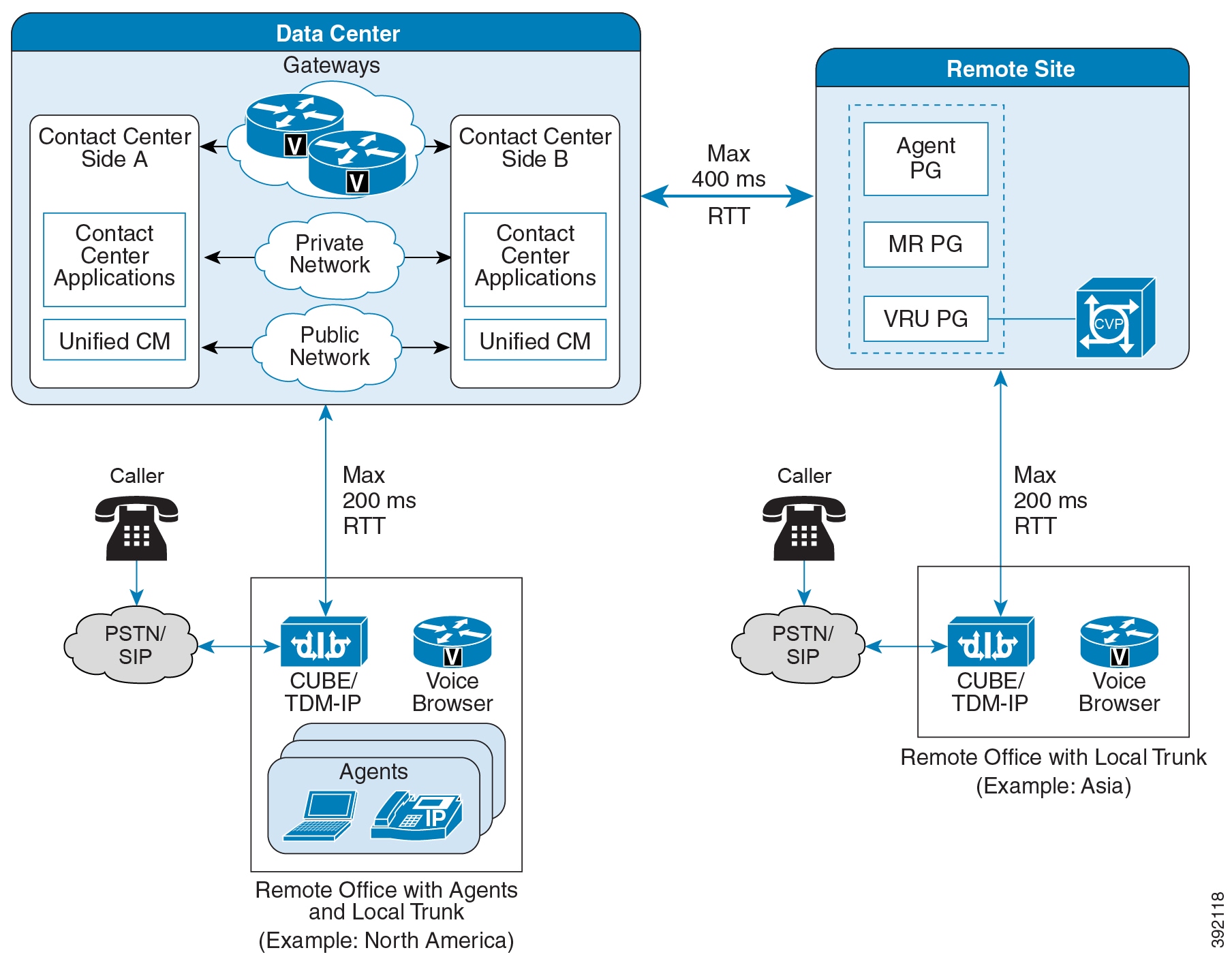
Remote Unified CM Deployment
If you have a remote office with agents, gateways, and Unified Communications Manager clusters, the Unified Communications clusters at the sites are typically independent. In this distributed call processing model, each site has its own Unified Communications cluster, with its own agents and PG pairs.
The following figure shows three Unified Communications Manager clusters. The remote office has a WAN connection back to the main site. Each Unified Communications Manager cluster is independent, with its own agents and PG pairs. Each site uses subscribers that are local to the site because JTAPI is not supported over the WAN. For example, site A cannot use the subscribers in site B. The Unified CCE central controller, Unified Intelligence Center, load balancer, SIP proxy server, and Unified CVP are located in the main site. TDM and VXML voice gateways are located at the remote office with local PSTN trunks.
Figure 38. Remote Unified Communications Manager Clusters Topology
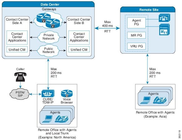
Remote CVP and Unified CM Deployment
The topology shown in the illustration shows a simple example of Remote CVP deployment. This deployment requires extra Unified CVP and Unified CM servers with Unified CCE Generic PG Servers at remote sites. The maximum RTT with central controller over the WAN is restricted up to 400ms.
Figure 39. Global Deployment Topology
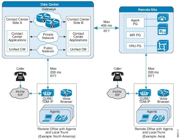
Remote Office Options
Remote agent support provides Computer Telephony Integration (CTI), contact distribution, and reporting capabilities to remote agents in branch offices or at home, through either a broadband network connection or their home phone line. Unified CCE provides identical user interfaces and feature functions to agents regardless of agent location.
The Unified Mobile Agent feature gives the contact center the flexibility to adapt to a fast-moving mobile workforce. Agents can choose their destination phone number during sign-in time and change the number as often as they want. Agents can be on any phone device on any third-party switch infrastructure.
Unified CCE remote office features help companies to use existing and on-demand resources and fully extend CTI functions across the extended enterprise.
Remote office options include:
Office with Unified CCE agents
Office with agent and a local trunk
Cisco Virtual Office
Mobile Agent
- Remote Office with Agents
- Remote Office with Agents and a Local Trunk
- Home Agent with Cisco Virtual Office
- Unified Mobile Agent
Remote Office with Agents
A remote office with agents is located either at the central office or at a branch office.
Remote Office with Agents
The following figure shows the physical view of a remote office with agents.
Figure 40. Remote Office with Agents—Physical View
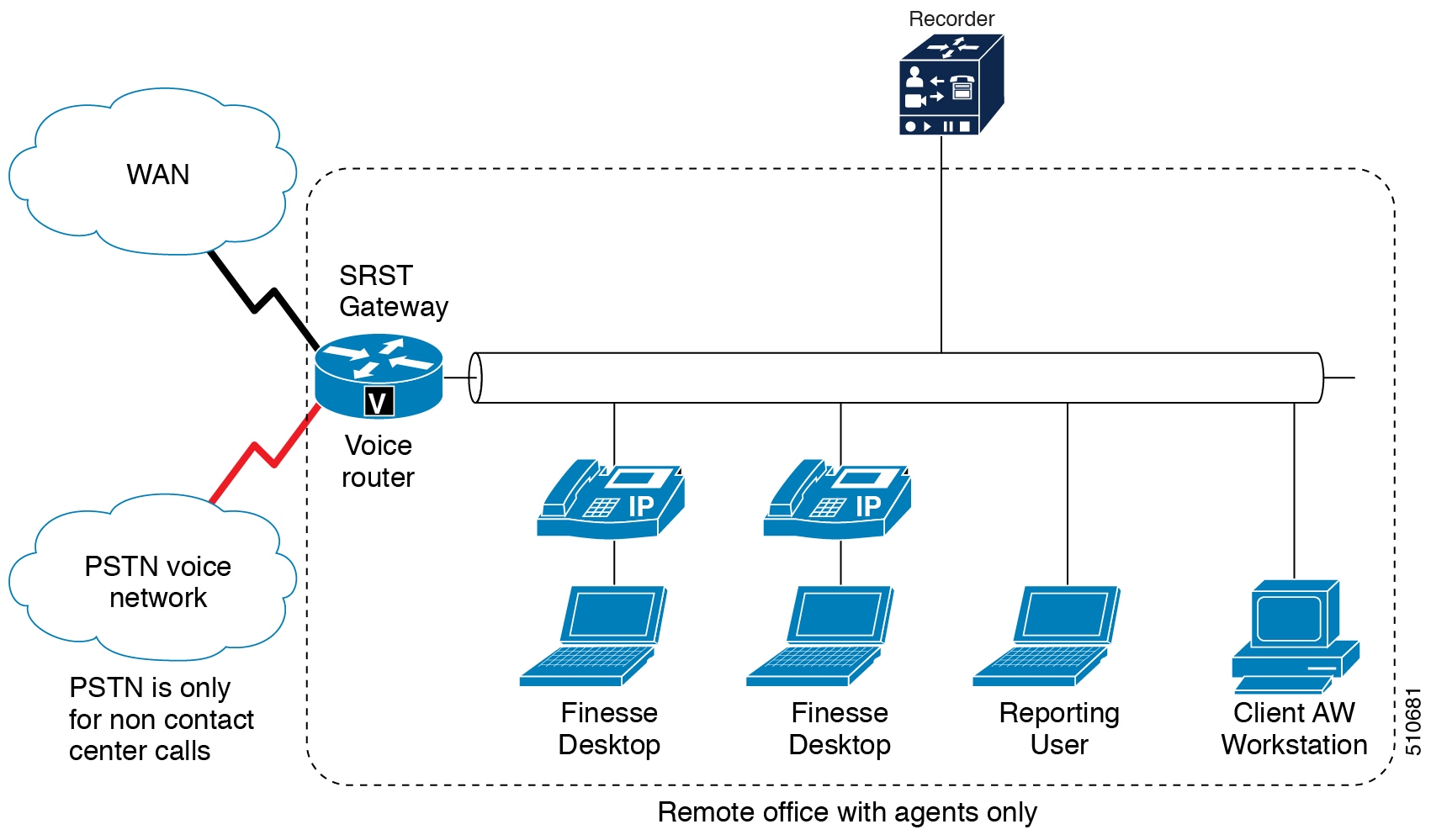
Remote Office with Agents Components
A remote office with agents includes the following components:
Unified Intelligence Center browser clients for local access to reporting
Administration tools: Unified CCE configuration tools, Internet Script Editor, or the local Administrative Workstation
Agent phones with BIB for Unified CM-based Silent Monitoring support
Remote Office with Agents Benefits
A remote office with agents provides the following benefits:
Requires only a small data switch and router, IP phones, and agent desktops at remote sites for a few agents.
Requires only limited system and network management skills at remote sites.
Small remote sites and offices do not require PSTN trunks.
PSTN trunks for incoming traffic connect to main site for efficiency.
Unified CCE queue points (Unified CVP) are aggregated for efficiency.
Does not use VoIP WAN bandwidth while calls queue. Calls extend over the WAN only when an agent is available for the caller.
Remote Office with Agents Design Requirements
The following table describes the design requirements for a remote office with agents.
Table 7. Remote Office with Agents Design Requirements
| Requirement | Notes | ||
|---|---|---|---|
| Infrastructure | Location-based call admission control | A failure of Unified CM location-based call admission control results in a disconnected routed call. Allow for adequate bandwidth to the remote sites and design a Quality of Service WAN. | |
Bandwidth | Plan bandwidth capacity for the following traffic:
| ||
Customer contact numbers | Customers might need to dial a long-distance number rather than a local PSTN number to reach the central office. You can offer customers a toll-free number, but the contact center incurs toll-free charges. | ||
Desktop | Cisco Finesse Customer Relationship Management | ||
Codec | G.711 or G.729a | G.711 requires more bandwidth than G.729a. | |
Recording | BIB Network-based Recording | Audio forking requires Unified Border Element. | |
| Silent Monitoring | Unified CM-based BIB |
The following table describes the media resources for a remote office with agents.
Table 8. Remote Office with Agents Media Resources
| Resource | Method | Notes |
|---|---|---|
Music on Hold | Unicast using Unified CM | |
Conference bridges | Hardware-based, located at voice gateways | Conference bridges use local Unified Survivable Remote Site Telephony (SRST). |
Media Termination Points | Hardware-based, located at voice gateways | For Unified Mobile Agents, MTPs are required only at the main site. |
Transcoders | Hardware-based, located at voice gateways | Transcoders use local Unified SRST. |
Remote Office with Agents and a Local Trunk
Use the remote office with agents and voice gateway deployment for contact centers with sites that each require local PSTN trunks for incoming calls. This deployment provides local PSTN connectivity for local calling and access to local emergency services.
Figure 41. Remote Offices with Agents and Local Trunks
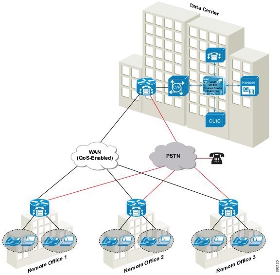
Remote Office with Agents and Voice Gateway Architecture
The following figure shows the physical view of a remote office with agents and voice gateway.
Figure 42. Remote Office with Agents and Voice Gateway—Physical View

Remote Office with Agents and Voice Gateway Components
A remote office with agents and voice gateway includes the following components:
Integrated Services Router (ISR) voice gateway for ingress voice customer calls under Unified CVP control with local PSTN. Unified SRST backup requires trunks.
Unified Intelligence Center browser clients for local access to reporting.
Administration tools: Unified CCMP browser clients, Internet Script Editor, or the local Administrative Workstation.
Optional third-party recording server for VoIP capture of agent or customer calls.
Agent phones with BIB for Unified CM-based Silent Monitoring support.
Remote Office with Agents and Voice Gateway Benefits
A remote office with agents and voice gateway provides the following benefits:
Requires only limited systems management skills for remote sites because most servers, equipment, and system configurations are managed from a centralized location.
Does not require WAN RTP traffic for calls that arrive at the remote site and agents handle there.
Unified CVP uses the VXML browser in Cisco IOS on the voice gateway to provide call treatment and queueing at the remote site. This call treatment and queueing eliminate the need to move the call over the VoIP WAN to a central queue and treatment point. VVB can provide the same capability locally.
Remote Office with Agents and Voice Gateway Design Requirements
The following table describes the design requirements for a remote office with agents and voice gateway.
Table 9. Remote Office with Agents and Voice Gateway Design Requirements
| Requirement | Notes | |
|---|---|---|
| Infrastructure | Location-based call admission control | A failure in Unified CM location-based call admission control results in a disconnected routed call. Allow for adequate bandwidth to the remote sites and design a QoS WAN. |
| Bandwidth | Plan bandwidth capacity for the following traffic:
| |
| Desktop | Cisco Finesse Customer Relationship Management | |
| Codec | G.711 or G.729a | G.711 requires more bandwidth than G.729a. |
| Recording | BIB | Audio forking requires a Unified Border Element. |
| Silent Monitoring | Unified CM-based BIB |
The following table describes the media resources for a remote office with agents and voice gateway.
Table 10. Remote Office with Agents and Voice Gateway Media Resources
| Resources | Method | Notes |
|---|---|---|
| Music on Hold | Unicast using Unified CM | |
| Conference bridges | Hardware-based, located at voice gateways | Conference bridges use local Unified SRST. |
| Media Termination Points | Hardware-based, located at voice gateways | For Unified Mobile Agents, MTPs are required only at the main site. |
| Transcoders | Hardware-based, located at voice gateways | Transcoders use local Unified SRST. |
- Call Admission Control Considerations
- Unified CM Call Administration Control
- Resource Reservation Protocol
- Call Admission Control Deployment
- Queue-at-the-Edge Branch Office Deployment
- Enhanced Location Call Admission Control Feature
- Distributed Network Options
Call Admission Control Considerations
Call admission control can be considered as a solution and not just a Unified CVP component. These considerations are most evident in the distributed branch office model where there are other voice services, such as Unified CM, sharing the same gateways with Unified CVP and the amount of bandwidth between the sites is limited. Be sure that, call admission control methods are in place on the network so that the same call admission control method is used for all the calls traversing the WAN from that site. If two call admission control methods can admit four calls each and the WAN link can handle only four calls, then it is possible for both call admission control entities to admit four calls onto the WAN simultaneously. This control method impairs the voice quality. If a single call admission method cannot be implemented, then each call admission control method must have bandwidth allocated to it. This situation is not desirable because it leads to inefficient bandwidth overprovisioning.
Two call admission control methods can be used in a Unified CVP environment: Unified CM Locations and Unified CM RSVP Agent. In a single-site deployment, call admission control is not necessary.
Unified CM performs call admission by assigning devices to certain locations and track of the number of calls that are active between these locations. Unified CM tracks the bandwidth that is used and, depending on the codec, can determine the number of calls.
Unified CM Call Administration Control
If Unified CM sends or receives calls from Unified CVP and there are Unified CVP gateways and IP phone agents collocated at remote sites, it is important to understand the call flows in order to design and configure call admission control correctly.
Resource Reservation Protocol
Resource Reservation Protocol (RSVP) is used for Call Admission Control, and it is used by the routers in the network to reserve bandwidth for calls. RSVP is not qualified for call control signaling through the Unified CVP Call Server in SIP. The solution for CAC is to use the Locations configuration on Unified CVP and in Unified CM.
Call Admission Control Deployment
Call admission control is the function for determining if there is enough bandwidth available on the network to carry an RTP stream. Unified CM can use its own locations function or RSVP to track bandwidth between the Ingress Gateway and destination IP phone locations.
In networks, Resource Reservation Protocol (RSVP) is a protocol used for call admission control, and it is used by the routers in the network to reserve bandwidth for calls. RSVP is not qualified for call control signaling through the Unified CVP Call Server in SIP. As an alternative, the solution for Call Admission Control is to employ locations configuration on Unified CVP and in Unified CM.
Queue-at-the-Edge Branch Office Deployment
The following figure illustrates a typical branch office deployment.
Figure 43. Typical Branch Office Deployment.
You can deploy Unified CVP in a single cluster Unified CM deployment to provide queue-at-the-edge functionality. In this deployment, use branch-located Ingress Gateways to give callers access by local phone numbers rather than centralized or nongeographic numbers. This consideration is especially important in international deployments spanning multiple countries. The goal of this deployment is to first route the calls locally to an agent available in the branch office, if possible. This keeps the media streams local.
You locate the Egress Gateways at the branches to provide either localized PSTN breakout or integration of decentralized TDM platforms (ACDs) into the solution. Apart from the gateways, all other CVP subcomponents are at the main site. WAN links provide data connectivity from each branch location to the main site. (Although the media server is centrally located, commonly used VRU media is cached at the local branch.)
In this deployment, the branch office only has an Ingress Gateway (optionally acting as a Voice Browser also), IP phones for agents, IPT phones, and agent desktops.
You can configure Unified CCE Skill Groups, dial plans, and routing priorities so that incoming calls at each branch preferentially connect to agents at the same branch. Then, the RTP traffic flows directly from the Ingress Gateway to the IP phone. The RTP traffic does not need to traverse the WAN (although signaling and data might traverse the WAN).
If a local agent is not available, only the call gets routed to a remote agent over the WAN link. The originating call and the initial VRU treatment are still done locally.
In a WAN link failure, the CVP survivability application running on the POTS dial-peer for TDM originated calls can still route incoming calls locally.
Enhanced Location Call Admission Control Feature
ELCAC Concepts
The following definitions are important to the ELCAC feature:
Phantom Location—A default location with unlimited bandwidth used when calculating calls that are hairpinned over a SIP trunk. You also use a phantom location when the SIP call is queued at the local branch to enable correct bandwidth calculations. Assign the phantom location to the gateway or trunk for CVP.
Location Routing Code—The Location Routing Code is a string of numbers that Unified CVP appends to the label it receives from Unified ICM. Depending on the Location Routing Code, configure the dial plan to route the call to a destination, like the branch Voice Browser or Egress Gateway, or a Unified CM node. You can append the Location Routing Code at the front of the label, between label and the correlation ID., or not at all. This configuration is separate from the Unified CM location configuration, and is specific to Unified CVP. The Location Routing Code indicates the real location of the call and enables you to deduct the bandwidth from the correct location. A Location Routing Code is unique across multiple Unified CM clusters. Multiple Location Routing Codes can still route to the same branch office (if needed) by mapping the unique Location Routing Codes to same branch gateways in proxy routes.
Shadow Location—This new location is used for intercluster trunks between two Cisco Unified Communications Manager clusters. This location is not used as intercluster ELCAC is not supported in Unified CVP.
Locations are created in Unified CM. Unified CVP gets these locations when you synchronize the location information from the Unified CM on Packaged CCE. You can associate a Location Routing Code for these locations on Packaged CCE and then associate your sites and gateways to these locations. Packaged CCE also enables you to create new locations. Based on this configuration, CVP creates two hash objects. One hash would map location to a Location Routing Code and the second hash would store mapping of GW IP address to location name and Location Routing Code. These hash objects enable routing the call to appropriate GW to provide edge queuing (using Location Routing Code). They also pass around the location information on the call legs for Unified CM to do proper CAC calculations.
For branch office deployments, the following considerations apply:
Control the number of calls that goes over the WAN link to branch offices based on the available bandwidth of the WAN link.
For the queue-at-the-edge functionality, route the call originating from a specific branch office to a local Voice Browser on priority.
For Unified CVP intracluster Enhanced Location CAC, control the number of calls that go over the WAN link to branch offices. The decision to admit calls is based on the CAC computations, which represent the bandwidth used by the call. These computations are valid whether the calls are IP calls between two phones within Cisco Unified Communications Manager, calls over SIP trunks, or calls originated from TDM-IP Gateway.
For queue-at-the-edge functionality, the call originating from a specific branch office must be routed to a local Voice Browser based on priority. That is, always choose a local branch agent if possible.
Unified CVP supports topology modeling with Enhanced Location Call Admission Control (ELCAC) for intracluster. It does not support intercluster Enhanced Location CAC. Location Bandwidth Manager is enabled for intracluster CAC, but disabled for intercluster CAC. For more information on ELCAC topology modeling, see the Cisco Unified Communications SRND based on Cisco Unified Communications Manager, available at http://www.cisco.com/c/en/us/support/unified-communications/unified-communications-manager-callmanager/products-implementation-design-guides-list.html.
Comparison of Enhanced Location Call Admission Control Feature
The Enhanced Location Call Admission Control (ELCAC) feature addresses two important issues with the prior CAC feature:
Bandwidth miscalculations in CAC with IP originated callers and with any post transfers from agents.
Inability to deterministically select a local Voice Browser for VRU treatment at the branch office. This occurs during warm transfers from an agent when there is no correlation between the two calls at consult.
With ELCAC, because the location information is in the call leg, calls are routed to a local gateway on agent transfer. On the VRU leg, CVP appends the site id to the call based on this location. The SIP Proxy can then use the site id to get to the local gateway.
Router Requery with ELCAC
When Unified CM rejects a call for insufficient bandwidth, a SIP message 488, Not Acceptable Here, is returned to Unified CVP. The message triggers a router requery over the GED-125 interface to the VRU peripheral. The Unified CCE Router can return another agent label if requery is configured properly.
Design Considerations
The following considerations apply when using ELCAC:
Associate the SIP trunk between Unified CVP and Unified CM with a Phantom location.
Note
Unified CM also has a shadow location for intercluster ELCAC. CVP does not support this.
In multicluster Unified CM deployments, consider oversubscribing bandwidth on WAN links based on the anticipated peak call volume. You can also choose a centralized branch office deployment, as intercluster ELCAC is not supported on Unified CVP.
In single-cluster Unified CM deployments, ELCAC is supported only for Hub and Spoke topology with Unified CVP.
The ELCAC feature does not work with a trunk configured that requires MTP. When MTP is inserted, the media terminates between the device and MTP resource, not between the two devices.
If the Unified CM media layer inserts a MTP/Transcoder/TRP media resource, the incoming location information is not used.
If the intercluster call is not looped back to the same cluster, the former behavior of Location CAC logic applies.
Each site has unique Location Routing Code. Align all gateways at the same site to the same Location Routing Code. If two clusters use the same location name, then two Location Routing Codes can map to the same physical branch.
A second Unified CM cluster may have the same location as the first cluster, but be required to use a unique Location Routing Codeon Unified CVP. You can define a route in the proxy server to send all calls at the same location to a common Voice Browser that both clusters use.
Each cluster would manage the bandwidth for devices in its cluster. If two clusters happen to use the same physical location, then they each separately manage the bandwidth for the phones that they manage.
Distributed Network Options
You can distribute the gateways in the following options:
Combined Branch Gateways—Enables call treatment at the edge and integration of locally dialed numbers into the enterprise virtual contact center. You have both the Ingress Gateway and the Voice Browser at the branch. If you use a Cisco IOS Voice Gateway, you can combine the Ingress Gateway and Voice Browser functions on it.
Branch Ingress Voice Gateways with Centralized Voice Browsers—Enables integration of locally dialed numbers and resource grouping of Voice Browser. This option supports organizations with many branches, with a few contact center calls in each branch. The VRU announcements in the centralized Voice Browsers traverse the WAN to the Ingress Gateway.
Branch Egress Gateways—Enables agents to transfer calls across the WAN to remote TDM terminations.
You can also use a combination of these distributed options.
Home Agent with Cisco Virtual Office
Cisco Virtual Office solutions boost flexibility and productivity by delivering secure, comprehensive, and manageable network services to teleworkers. They supply full IP phone, wireless, data, and video services over an encrypted VPN. Cisco Virtual Office delivers a transparent, office-caliber experience. Video playback is smooth, voice doesn't stutter, and wireless connectivity is effortless.
In a Cisco Virtual Office, the VPN router requires QoS capability for the desktop. Include in your calculations the bandwidth for Unified Intelligence Center, the agent desktop, and extra call flows such as recording.
Remember that broadband has no guarantee on bandwidth. Because of this, your broadband link needs greater capacity than the minimum requirement for the contact center traffic. The greater bandwidth enables the agent to stay active during peak times.
Unified Mobile Agent
Unified Mobile Agent supports call center agents using phones that Unified CCE does not directly control. A mobile agent can be physically located either outside or inside the contact center.
Outside the contact center—The agent uses an analog phone in the home or a mobile phone.
Within the contact center—The agent uses an IP phone connection that Unified CCE or Unified Communications Manager does not control.
In addition, a mobile agent can be available through different phone numbers at different times; the agent enters the phone number at sign-in time. The agent can access Unified Mobile Agent using any phone number, as long as the agent can dial the number using the Unified CM Dial Plan.
System administrators configure the Unified Mobile Agent to use a nailed (permanent) or call-by-call connection. Mobile agents can participate in outbound campaigns, but they can only use the nailed connection mode for all outbound dialing modes.
Unified Mobile Agent Components
The Unified Mobile Agent deployment scenario includes the following components:
Cisco Virtual Office cable/DSL router for secure VPN data connectivity to the sites (no voice)
Agent uses local phone with traditional local phone service to accept inbound calls
Cisco Finesse desktops connect to Cisco Virtual Office cable/DSL router
Administration tools: Unified configuration tools, Internet Script Editor, or the local Administrative Workstation
Unified Mobile Agent Benefits
The Unified Mobile Agent deployment scenario provides the following benefits:
Unified Mobile Agent can send calls to any PSTN or mobile phone. This extends the reach of a centralized IP contact center.
Contact centers can hire skilled employees where they live and integrate remote workers into geographically dispersed teams with access to equivalent corporate applications.
Contact centers can reduce startup costs by bringing temporary agents online during seasonal high call volume. Agents can choose their destination phone number during sign-up time. They can change the number as often as they want, giving the contact center the flexibility to adapt to a fast-moving mobile workforce.
The mobile agents have equal access to applications and services as agents at the central site. These geographically dispersed agents create a built-in backup plan to keep business processes functioning in unforeseen circumstances.
Unified Mobile Agent Design Requirements
The following table describes the design requirements for Unified Mobile Agent.
Table 11. Unified Mobile Agent Design Requirements
| Requirement | Notes | |
|---|---|---|
Configuration | Dial plan | For mobile agents on a dedicated gateway, all calls from the CTI ports go through a specific gateway at the site regardless of which phone number is called. |
Define the local CTI port directory number (DN), which is the routing label when the agent is selected. | ||
To keep the mobile agent signed in, set the values for both the Maximum Call Duration timer and Maximum Call Hold timer to 0. To configure these timers, use the Unified CM Administration web page for service parameters using Unified Communications Service. | ||
The Cisco Unified Mobile Agent connect tone provides an audible indication when a call is delivered to the nailed connection mobile agent. The connection tone is two beeps, which the nailed connection mobile agent hears when answering a call. This feature is turned off by default. Use the PG registry key PlayMAConnectTone to enable the Cisco Unified Mobile Agent connect tone. | ||
SIP trunk (CUBE) | CUBE dynamically changes the media port during the call. If you use the Mobile Agent feature, the SIP trunk that connects to the agent endpoint requires MTP resources. | |
Codec | G.711 or G.729 | Ingress and egress voice gateways can be G.711 or G.729 but not a mix of both. All CTI ports for a PG must advertise the same codec type. All mobile agents should use the same codec, but local agents on the supervisor's team can use a mix of codecs. Configure the gateway MTPs to do a codec pass-through because the Mobile Agent uses G.729 and the rest of the components support all the codecs. |
Infrastructure | DNS | You must have a DNS entry for the mobile agent desktop. If you do not have a DNS entry for the mobile agent desktop, the agent cannot connect to a CTI server. |
Firewall | If an agent with a nailed connection is idle longer than the firewall idle timeout value, the firewall can block the media stream. To prevent this, increase the firewall idle timeout value. | |
Bandwidth | Minimum supported bandwidth speed:
Use bandwidth calculators to ensure that you provide sufficient bandwidth. QoS is enabled only at the remote agent router edge. Currently, service providers do not provide QoS. | |
Latency | The mobile agent round-trip delay to the Unified CCE site must not exceed 200 ms. The mobile agent jitter delay must not exceed 60 ms. | |
Voice gateways | Use egress gateways for mobile agents. | |
Call control | Use RONA when a mobile agent is signed in and ready, but is unavailable to answer a call. | |
A mobile agent on one PG can only make blind transfers and conferences to a mobile agent on another PG in the same Unified CM cluster. | ||
Phones | Disable agent phone call features such as call waiting, call forwarding, and voicemail. | |
Agent workstation | Set up the mobile agent workstation to use DHCP. | |
Security | Enable security features on the remote agent router. | |
Desktop | Cisco Finesse | Cisco Finesse does not support Switched Port Analyzer (SPAN) port silent monitoring. |
Recording | SPAN port Network-based Recording | Recording server in the site. |
Silent Monitoring | Not available |
The following table describes Unified Mobile Agent media resources.
Table 12. Unified Mobile Agent Media Resources
| Resource | Method | Notes |
|---|---|---|
| Music on Hold | Unified CM unicast | If the MoH server does not stream using a G.729 codec, then set up a transcoder to enable outside callers to receive Music on Hold. |
| Conference bridges | Voice gateways in the site | Agent greeting requires a conference bridge. |
| Media Termination Points | Voice gateways in the site | Assign two MTPs for each Unified Mobile Agent:
CTI ports do not support in-band Dual-Tone Multifrequency (DTMF) RFC 2833. The MTPs perform the conversion. Do not place MTPs at the egress gateway. If you use SIP trunks, configure Media Termination Points (MTPs). Enabling the use of an MTP on a trunk affects all calls that traverse that trunk, even noncontact center calls. Ensure that the number of available MTPs can support the number of calls traversing the trunk. |
| Transcoders | Voice gateways in the site | All mobile agents must have the same codec: G.711 or G.729. |
Solution Administration
The contact center enterprise solutions offers several sets of primary administration tools.
Service Creation Environments
The contact center enterprise solutions include two service creation environments:
Unified CVP Call Studio—The Call Studio is a platform for rapidly creating, managing, and deploying sophisticated dynamic VXML self-service applications. The Call Studio application runs in the Eclipse framework. You do not need knowledge of Eclipse to work with the Call Studio. The Call Studio includes plug-ins for voice application development, Java programming, and many other features provided by Eclipse.
Unified CCE Script Editor—The Script Editor is a tool for creating, updating, scheduling, and monitoring your routing scripts and administrative scripts.
Figure 44. Service Creation Environment
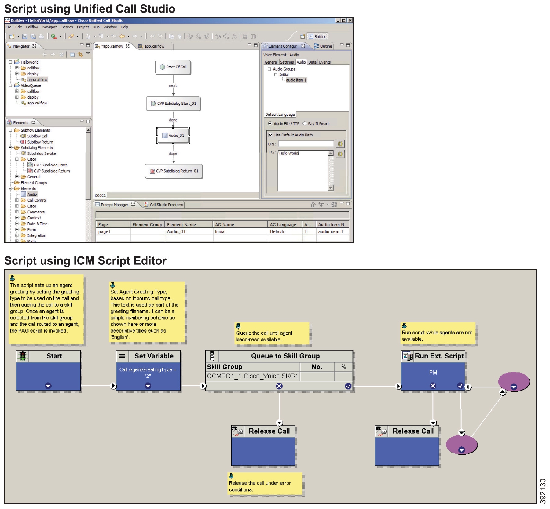
Solution Serviceability and Monitoring
The contact center enterprise solutions support several solution serviceability tools. These tools leverage similar interfaces (SNMP, Syslog, Diagnostic REST/SOAP API, telnet/SSH CLI interface) from each component of the solution but provide unique features and functionality.
Analysis Manager
Prime Collaboration Assurance
Unified System CLI
Also, you could use third-party SNMP and network management tools as well to monitor and perform solution serviceability.
- Prime Collaboration Manager
- Analysis Manager
- Unified System CLI
- Analysis Manager vs Unified System CLI
- Third-Party Network Management Tools
- System Performance Monitoring Guidelines
- End-to-End Individual Call Tracking
Prime Collaboration Manager
For managing a Unified Communications deployment, customers are encouraged to use the Cisco Prime Collaboration Assurance product. Cisco Prime Collaboration Assurance is a member of the Cisco Unified Communications family of products and provides a comprehensive and efficient solution for network management, provisioning, and monitoring of Cisco Unified Communications deployments.
Cisco Prime Collaboration Assurance monitors and evaluates the current status of both the IP communications infrastructure and the underlying transport infrastructure in your network. Cisco Prime Collaboration Assurance uses open interfaces such as SNMP and HTTP to remotely poll data from different devices in the IP communications deployment.
Cisco Prime Collaboration Assurance is a comprehensive video and voice assurance and management system with a set of monitoring, troubleshooting, and reporting capabilities that help ensure end users receive a consistent, high-quality video and voice collaboration experience. You deploy Prime Collaboration in Managed Service Provider (MSP) mode. The following are the key features of Cisco Prime Collaboration.
Voice and Video Unified Dashboard
Device Inventory Management
Voice and Video Endpoint Monitoring
Diagnostics
Fault Management
Reports
Live Contact Center topology with link status, device status, device performance, device 360
Contact Center device discovery
Contact Center devices real time performance monitoring
Events and Alarms along with root cause analysis
Contact Center device Dashboards - Prebuilt and custom
Threshold, Syslog, Correlation and System Rules - Prebuilt and custom
Multi-tenancy and logged-in agent licensing information
Analysis Manager
The Analysis Manager functionality integrated with the Unified Communications Manager Real-Time Monitoring Tool (RTMT) is provided as the client-side tool to collect diagnostic information from this diagnostic framework.
Using the Analysis Manager, the administrator connects to one or more Unified Communications devices to set trace levels, collect trace and log files, and gather platform and application configuration data as well as version and license information. The Analysis Manager is the one tool that allows administrators to collect diagnostic information from all Cisco Unified Communications applications and devices.
The Analysis Manager offers local user and domain security for authentication and secure HTTP to protect data exchanged by it and the diagnostic framework.
The Web Service Manager supports all diagnostic (health and status) requests from the Analysis Manager. The Analysis Manager is part of UCM RTMT tool. It provides users an interface for collecting health and status information for all devices in its network topology. If Unified CVP is configured as a part of the solution, you can leverage the WSM through the Analysis Manager to collect diagnostic details, such as server map, version information, licenses, configuration, components, logs, traces, performance factors, platform information for each CVP Device on a component and subcomponent level. You can set or reset debug levels using the Analysis Manager on a component and subcomponent level.
A new user with the wsmadmin username is created during installation with the same password as the Operations Console Server administrator user. Use wsmadmin to control access to the diagnostic portal services.
Unified System CLI
In addition to the Analysis Manager, a command line interface-Unified System CLI tool-is available that allows a client to access the diagnostic framework on any Unified Communications server. The Unified System CLI can be accessed without a remote desktop.
When an issue arises in your solution, use the System CLI tool to collect data for review by Cisco engineers. For example, you can use the System CLI if you suspect a call is handled incorrectly. In this case, you can use the show tech-support command to collect data and send the data to Cisco support.
Unified System CLI has the following features:
Is automatically installed on all Unified CVP Servers as part of the infrastructure. No additional installation is required on any Unified CVP server.
Uses a consistent command across the solution.
Can be run as a Windows scheduled job.
The following figure shows the high-level commands for the Unified System CLI and shows the interaction of devices and Unified Cisco products.
Figure 45. High-Level Commands for Unified System CLI
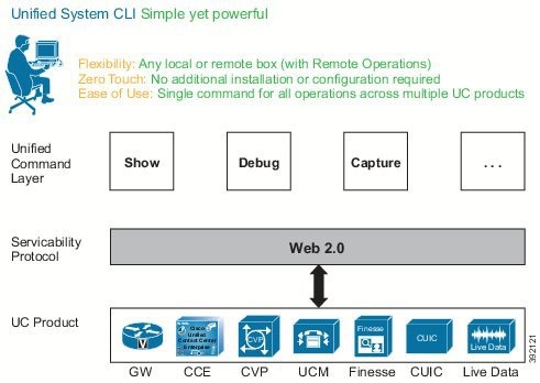
Unified System CLI runs at a low priority; it uses idle CPU time on the system. It should not affect call processing even if run on a system running under load.
The response time from the given CLI command varies depending on the load of the system and the server response time. The response time when there is no running load should be below 5 seconds for each server for operations, such as show version, show license, show debug, and show perf. The response time when there is no running load for show platform operation should be below 10 seconds for each server.
However, the response time cannot be determined for commands, such as show trace, show log, show sessions, show all, and show tech-support. The response for these commands can vary depending on the data being transferred by the server.
Unified System CLI Modes of Operation
The Unified System CLI operates as an interactive user interface and can also be used as a batch command. This feature allows the Unified System CLI to be used in scheduled jobs.
The Unified System CLI can operate interactively as follows:
Local mode—In this mode, the Unified System CLI only interacts with a single device. For example, the show version command shows only the version for a single device.
Analysis Manager vs Unified System CLI
Analysis Manager and Unified System CLI access the Diagnostic Portal API. Both the Analysis Manager and the Unified System CLI have similar features, except for the differences shown in the table.
Table 13. Differences Between Analysis Manager and Unified System CLI
Analysis Manager | Unified System CLI |
|---|---|
Is a GUI-based client that is part of the Unified CM Real-Time Monitoring Tool (RTMT). The Analysis Manager has a user-friendly interface due to its GUI- based design. | Is a command line based tool. The Unified System CLI is more flexible because it can be used in a batch file to perform more complex tasks. |
Is neither bundled with CVP nor installed by Unified CVP installer. | Is bundled with Unified CVP installer, and is also bundled with the Unified CCE installer. |
Third-Party Network Management Tools
Unified CCE is managed using the Simple Network Management Protocol (SNMP). Unified CCE devices have a built-in SNMP agent infrastructure that supports SNMP v1, v2c, and v3 and it exposes instrumentation defined by the CISCO-CONTACT-CENTER-APPS-MIB. This MIB provides configuration, discovery, and health instrumentation that you can monitor with standard SNMP management stations. Unified CCE provides a rich set of SNMP notifications that alerts administrators of any faults in the system. Unified CCE also provides a standard syslog event feed (conforming to RFC 3164) if you need a more verbose set of events.
Unified CVP and Unified Intelligence Center support SNMP v2 and v3.
Cisco Finesse and Customer Collaboration Platform only support SNMP from the VOS platform. You cannot use SNMP directly from the Cisco Finesse and Customer Collaboration Platform applications.
You can use Simple Network Management Protocol (SNMP) station to monitor the solution deployment status.
Unified CCE has a built-in web-based (REST-like) interface for diagnostics called the Diagnostic Framework, which is resident on every Unified CCE server.
System Performance Monitoring Guidelines
Supporting and maintaining an enterprise solution requires many steps and procedures. Depending on the customer environment, the support procedures vary. System performance monitoring is one procedure that helps maintain the system. This section provides a guide for monitoring Unified CCE to ensure that the system is performing within system tolerances. System monitoring is especially critical for customers as they expand or upgrade their system. Monitor the system during times of heavy activity.
The following system components are critical to monitor:
CPU
Memory
Disk
Network
The following table highlights some of the important counters for the critical system components, along with their threshold values:
Table 14. Monitoring Threshold Values
Monitored Resource | Thresholds |
|---|---|
CPU | %Processor Time; the threshold of this counter is 60%. ProcessorQueueLength; this value must not exceed (2 * [the total number of CPUs on the system]). |
Memory | % Committed Bytes; this value must remain less than (0.8 * [the total amount of physical memory]). Memory\Available MByte; this value must not be less than 16 MB. Page File %usage; the threshold for this counter is 80%. |
Disk | AverageDiskQueueLength; this value must remain less than (1.5 * [the total number of disks in the array]). %Disktime; this value must remain less than 60%. |
Network | NIC\bytes total/sec; this value must remain less than (0.3 * [the bandwidth of the NIC]). NIC\Output Queue Length; the threshold for this counter is 1. |
Unified CCE | Cisco Call Router(_Total)\Agents Logged On Cisco Call Router(_Total)\Calls in Progress Cisco Call Router(_Total)\calls /sec |
In general, the 95th percentile for your busy hour traffic should not exceed these thresholds.
| Note | These performance counters for CPU, memory, disk, and network are applicable to all Windows-based applications within the deployment. The sample rate is 15 seconds. For more information on monitoring your VMs, see Cisco Collaboration Virtualization at http://www.cisco.com/c/dam/en/us/td/docs/voice_ip_comm/uc_system/virtualization/cisco-collaboration-virtualization.html. |
End-to-End Individual Call Tracking
When a call arrives at the Ingress Gateway, Cisco IOS assigns that call a 36-digit hexadecimal Global Unique Identifier (GUID), which identifies the call. The contact center carries that GUID through all of the components that the call encounters, as follows:
Ingress gateway—Shown in Cisco IOS log files.
Voice Browser—Shown in Cisco IOS and Cisco VVB log files.
Unified CVP components—Shown in Unified CVP log files.
Unified CCE—Shown in the Extended Call Context (ECC) variable
user.media.idand stored with all Termination Call Detail (TCD) and Route Call Detail (RCD) records.Automatic speech recognition (ASR) and text-to-speech (TTS) servers—Shown in logs as the logging tag.
Cisco Unified Communications Manager (Unified CM)—Appears in the detailed logs.
With proper levels of logging enabled, you can trace a call through all these components.
Localization
The contact center enterprise solutions concentrate on providing localization support for the agent and supervisor desktops. Most of the administration tools use exclusively English. The tools accept characters from the appropriate Windows code page for your SQL collation in these values:
Agent names
Peripheral variables
ECC variables
Description fields of ICM tables
Wrap-up data
Reason codes
However, you always enter characters from left to right in the tools. Each Unified CCE instance can only support one Windows code page in the database. The Compatibility Matrix for your contact center enterprise solution lists the supported localized versions of Microsoft Windows Server and SQL Server that you can use with your solution.
For example, with Latin1_General for the SQL collation, agent names can contain any language written in the Western European character set (Windows code page 1252). These include Afrikaans, Basque Catalan, Georgian, Indonesian, Irish, and Malay. With Cyrillic_general for the SQL collation, agent names can contain any languages written in Cyrillic (Windows code page 1251). These include Bulgarian, Kyrgyz, Mongolian, Uzbek, Serbian, and Ukrainian.
For more information on localization of the Finesse desktop, see the Cisco Finesse Administration Guide at http://www.cisco.com/c/en/us/support/customer-collaboration/finesse/products-user-guide-list.html.
Multi-Language Support
The Voice Browser and the Media Resource Control Protocol (MRCP) specification do not restrict support for multiple languages. However, your Automatic Speech Recognition (ASR) or TTS Server might have restrictions for this. Check with your preferred ASR or TTS vendor about their support for your languages before preparing a multilingual application.
You can dynamically change the ASR server value with the cisco property com.cisco.asr-server command in the VXML script. This property overrides any previous value set by the VXML script. Similarly, you can change the TTS server with cisco property com.cisco.tts-server command in the VXML script.
 Feedback