- Preface
- Cisco Unified Contact Center Solutions
- Unified CCE Reference Designs
- Contact Center Enterprise Solutions Overview
- Configuration Limits and Feature Availability for Reference Designs
- Packaged Contact Center Enterprise Solution Design Considerations
- High Availability and Network Design
- Design Considerations for Integrated Features
- Bandwidth, Latency, and QoS Considerations
- Sizing and Operating Conditions for Reference Designs
- Avaya and ICM-to-ICM Gateway Support
- Solution Security
- Introduction to the Reference Designs
- Benefits of a Reference Design Solution
- Specifications for a Reference Design Solution
- Contact Center Enterprise Reference Designs
- Topologies for Reference Designs
Introduction to the Reference Designs
 Note | The first four chapters of this book are for anyone who wants to get familiar with the three contact center enterprise solutions:
|
The Contact Center Enterprise Reference Designs are a set of Cisco validated designs of our contact center enterprise solutions. The Reference Designs define the technologies and topologies that fit the needs for most deployments. The Reference Designs focus on simplifying the contact center enterprise solution design. They provide complete contact center functionality based on components that are strategic to Cisco.
We have defined the Reference Designs in the following table to cover most contact center needs:
Table 1. Reference Design Use by Contact Center Enterprise Solution
Reference Design | Packaged CCE | Cisco HCS for Contact Center | Unified CCE |
|---|---|---|---|
2000 Agents | Yes | Yes | Yes |
4000 Agents | Yes | Yes | Yes |
12000 Agents | Yes | Yes | Yes |
24000 Agents | No | Yes | Yes |
Contact Director | No | No | Yes |
If your solution exceeds the configuration limits for a particular Reference Design, use a Reference Design with higher limits. For example, if your 2000-agent deployment requires 350 active reporting users, use the 4000 Agent Reference Design for your solution.
Reference Designs and Deployment Types
The Contact Center Enterprise Reference Designs are mapped to specific contact center solutions through deployment types. Deployment types are system codes that impose system limits and apply congestion control.
This table maps the Reference Designs and Non-Reference Designs with the deployment type that you use for each.
Table 2. Deployment Type Usage by Reference Design
Reference Design | Packaged CCE | Cisco HCS for Contact Center | Unified CCE |
|---|---|---|---|
Label | Label | Label | |
2000 Agent | Packaged CCE: 2000 Agents | HCS-CC: 2000 Agents | UCCE: 2000 Agents |
4000 Agent | Packaged CCE: 4000 Agents | HCS-CC: 4000 Agents | UCCE: 4000 Agents |
12000 Agent | Packaged CCE: 12000 Agents | HCS-CC: 12000 Agents | UCCE: 12000 Agents |
24000 Agent | NA | HCS-CC: 24000 Agents | UCCE: 24000 Agents Router/Logger |
Contact Director | NA | NA | Contact Director |
Non-Reference Designs | Avaya PG and ICM-to-ICM Gateway Packaged CCE: 4000 Agents Packaged CCE: 12000 Agents | NA | ICM Rogger |
ICM Router/Logger | |||
UCCE: 8000 Agents Router/Logger | |||
Lab Only Designs | Packaged CCE: Lab Mode | NA | UCCE: Progger (Lab Only) |
| Note | After a Packaged CCE deployment is initialized, you cannot switch to another Packaged CCE deployment type. However, you can switch to a Unified CCE deployment type. |
Benefits of a Reference Design Solution
Contact centers offer more possibilities with each new generation of software and hardware. New technology can make previously preferred methods obsolete for current contact centers. We created the Contact Center Enterprise Reference Designs to simplify your design choices and speed the development of your contact center. We expect that most new contact centers can use the Reference Designs to meet their needs.
By following the Reference Designs, you can:
Guide your customers' expectations by presenting clear options.
Streamline your design process with standard models.
Avoid using components and features that are near the end of their lifecycle.
Find powerful and efficient replacements for obsolete features.
Align your designs with Cisco's vision of our future contact center developments.
Enjoy quicker and easier approval processes.
Specifications for a Reference Design Solution
The Reference Designs define our vision of the functionality that most contact centers use. The Reference Designs consist of:
Core components—Components that make up every contact center:
Ingress, Egress, and VXML Gateways
Unified Customer Voice Portal (Unified CVP)
Unified Contact Center Enterprise (Unified CCE)
Cisco Virtualized Voice Browser (VVB)
Unified Communications Manager (Unified CM)
Cisco Finesse
Cisco Unified Intelligence Center
Optional Cisco components—Components that add functionality that not every contact center needs.
Customer Collaboration Platform
Cisco Unified SIP Proxy
Enterprise Chat and Email
Cisco IdS
Cloud Connect
Optional third-party components—Third-party components that you can add to provide other features.
Load balancers
Recording
Speech servers - ASR/TTS
Wallboards
Workforce management
Integrated features—These features do not require you to add an optional solution component to enable them. But, these features can require configuration in multiple solution components to activate them. They can affect your solution sizing and might have specific design considerations.
Call flows—Standard contact handling and routing methods.
Inbound Calls:
New calls from a carrier
New internal calls
Supplementary services
Hold and resume
Transfers and conferences
Refer transfers
Network transfers
Requery and survivability
Topologies—Standard layouts for your contact center components:
Centralized
Distributed
Global
This figure shows the high-level services that are part of the solutions and the components that provide those services. It also highlights some features and components that are outside of the Reference Designs:
| Note | This figure highlights only a few Non-Reference Design components and topologies. The Non-Reference Design sections expand on this list. |
Figure 1. Contact Center Enterprise Components and Features
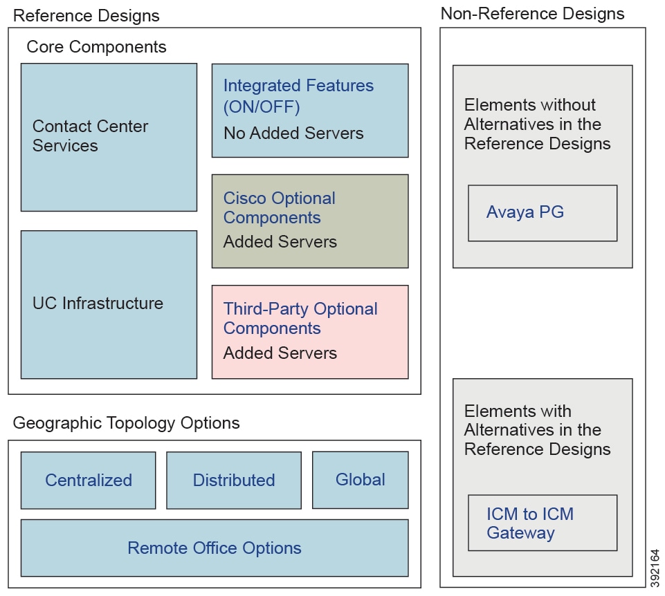
| Note | In general, you cannot use the ICM-to-ICM Gateway in Reference Designs. Only the Contact Director Reference Design allows you to use that gateway. |
This figure encapsulates the basic requirements of a Reference Design-compliant deployment:
Figure 2. Contact Center Enterprise Components and Features
Contact Center Enterprise Reference Designs
The following sections describe the Contact Center Enterprise Reference Designs .
The Reference Designs are supported for Cisco UCS C240 M5SX, Cisco UCS C240 M6SX, and Cisco HX220c-M5SX Tested Reference Configuration (TRC) servers as detailed in the Cisco Collaboration Infrastructure Requirements wiki: https://www.cisco.com/c/dam/en/us/td/docs/voice_ip_comm/uc_system/virtualization/cisco-collaboration-infrastructure.html.
| Note | For more details on supported servers for the Reference Designs , see the Cisco Collaboration Virtualization page for your solution at http://www.cisco.com/c/dam/en/us/td/docs/voice_ip_comm/uc_system/virtualization/cisco-collaboration-virtualization.html. |
The following notes apply to all the Reference Designs:
Contact Center Enterprise solutions use vCPU oversubscription.
The standard PG VM includes an Agent (Unified CM) PG, a VRU PG, and an MR PG. Unified CCE and Cisco HCS for Contact Center allow you to add more PGs and their peripherals onto this base layout.
Cloud Connect, a component that allows you to use cloud services, is available only with Cisco Webex Experience Management.
Cloud Connect can be on-box (as depicted in the following sections) for deployments on the Cisco HX220c-M5SX server, whereas, on the Cisco UCS C240 M5SX or Cisco UCS C240 M6SX servers, Cloud Connect must be off-box.
CVP Reporting server, Cisco VVB, and Cloud Connect are optional components.
The TRC layouts for Cisco UCS C240 M5SX and Cisco UCS C240 M6SX servers are identical. Note that only a single-socket 28-core CPU is used for the Cisco UCS C240 M6SX servers. If customers wish to use the additional socket on the Cisco UCS C240 M6SX servers with corresponding increase in cores, memory, and disks, the hardware will be supported under spec-based VM provisioning policies.
Cisco HX220c-M6S servers are supported in accordance with spec-based policies only.
CVP Reporting server and Cisco VVB are optional components.
Based on your business and deployment requirements, you may distribute the VVB VMs on external servers, or as depicted in this section, deploy them on additional servers or nodes (in the case of M5-HX clusters).
If the layout is on the Cisco HX220c-M5SX or Cisco HX220c-M6S server, you can deploy the additional VVB servers on HX nodes in the same cluster, or on external M5 or M6 servers, respectively.
VVB with AppD enabled CPU MHz utilization spikes during services start up. VVB OVA profiles has upper threshold set as unlimited so there are no changes in OVA profile. This impact is only during services start up but not under general or load scenarios.
An HX cluster can consist of a combination of compute and converged nodes, provided that all resource requirements and resource constraints are satisfied in accordance with the Virtual Machine Resource Provisioning Policy. This is supported only as a spec-based deployment model.
For information on the data source allocation of the components in the Reference Design layouts, see the Cisco Packaged Contact Center Enterprise Installation and Upgrade Guide at https://www.cisco.com/c/en/us/support/customer-collaboration/packaged-contact-center-enterprise/products-installation-guides-list.html
The Reference Design layouts in this section do not show off-box components like Customer Collaboration Platform.
If you upgrade to Release 12.6(1) on Cisco UCS C240 M4SX server, we recommend that you install an additional 32 GB of memory on all servers to accommodate the increased memory requirements of the Release 12.6(1) VMs.
- Virtual Machines Resource Provisioning Policy
- 2000 Agent Reference Designs
- 4000 Agent Reference Designs
- 12000 Agent Reference Designs
- Contact Director
Virtual Machines Resource Provisioning Policy
| Note | The previously used Oversubscription policy is a part of the Virtual Machine (VM) Resource Provisioning Policy. |
The Unified CCE Reference Designs support the virtual machine vCPU oversubscription of the physical CPU cores on a server. For the purposes of oversubscription, the hyper-thread cores do not count as physical cores. Whether or not you use oversubscription, use the VM Resource Provisioning policy. This policy limits the total available CPU MHz and the memory of a server that the host-resident VMs can consume.
Apply the VM Resource Provisioning policy when:
You provision a Reference Design server for optional and third-party components that are not given a reference VM layout.
You use UCS servers.
You upgrade an existing solution and do not migrate to a Reference Design VM layout.
| Note | Apply the VM Resource Provisioning policy on a per-server basis. This policy does not apply to the Reference Design VM layouts. Your solution can contain servers that use the Reference Design VM layouts and other VM layouts that use the VM Resource Provisioning policy rules. |
The application of the VM Resource Provisioning policy requires meeting the following conditions:
You can use up to two vCPUs for every physical core on each server.
You can use up to 65% of the total available CPU MHz on each server.
You can use up to 80% of the total available memory on each server.
For more information on virtualization and specification-based server policies, see the Cisco Collaboration Virtualization at http://www.cisco.com/c/dam/en/us/td/docs/voice_ip_comm/uc_system/virtualization/cisco-collaboration-virtualization.html.
| Note | The Virtual Machine Placement Tool does not currently allow you to oversubscribe. This limitation is only an issue with the tool. You can oversubscribe within the limits that are provided here. |
2000 Agent Reference Designs
All contact center enterprise solutions support the 2000 Agent Reference design on the Cisco UCS C240 M5SX or Cisco UCS C240 M6SX and the Cisco HX220c-M5SX Large TRC servers.
In this Reference Design, Cisco Unified Intelligence Center, Live Data, and the Identity Service for Single Sign-On are coresident on a single VM. In the larger Reference Designs, they reside in separate VMs.
You can optionally deploy the Unified Communications Manager Publisher and Subscribers on separate servers, instead of deploying them as shown in the 2000 Agent Reference Design layout. You should dedicate two of the subscribers to Unified CCE. All devices on these subscribers must be SIP.
In 2000 Agent Reference Designs, a coresident Unified CM can support a maximum of 2000 phones. This includes your phones for all types of agents, whether contact center agents or back-office workers. If your solution requires more than 2000 phones, use a Unified CM on a separate server instead.
In the global deployment topology, each remote site can have its own Unified CM cluster. A remote site cannot include a Cisco Unified Intelligence Center server.
In Packaged CCE global deployments, you cannot create a remote site without PG VMs.
You can deploy optional AW-HDS-DDS per site on external servers for longer data retention.
In 2000 Agent Reference Designs, you can deploy ECE Data Server on-box for up to 400 agents. Deploy ECE off-box for up to 1500 agents.
You can also deploy the ECE Data Server on a separate server.
Deploy the ECE Web Server on an external server. You can place that server either in the same data center as the ECE Data Server or in a DMZ if customer chat interactions require that.
| Note | Adding more disks is not permitted in the Packaged CCE 2000 agent deployment. Any changes to the number of disks will result in a VM validation error. |
- Support on the Cisco UCS C240 M5SX and Cisco UCS C240 M6SX Large TRC Servers
- Support on the Cisco HX220c-M5SX TRC Server
Support on the Cisco UCS C240 M5SX and Cisco UCS C240 M6SX Large TRC Servers
| Important | If you plan to upgrade to 12.x on Cisco UCS C240 M4SX servers, deploy Unified CM and ECE HA VMs on external servers. |
The following figure shows the base layout of the components in a 2000 Agent Reference Design on Cisco UCS C240 M5SX and Cisco UCS C240 M6SX Large TRC servers.
Figure 3. 2000 Agent Reference Design Model
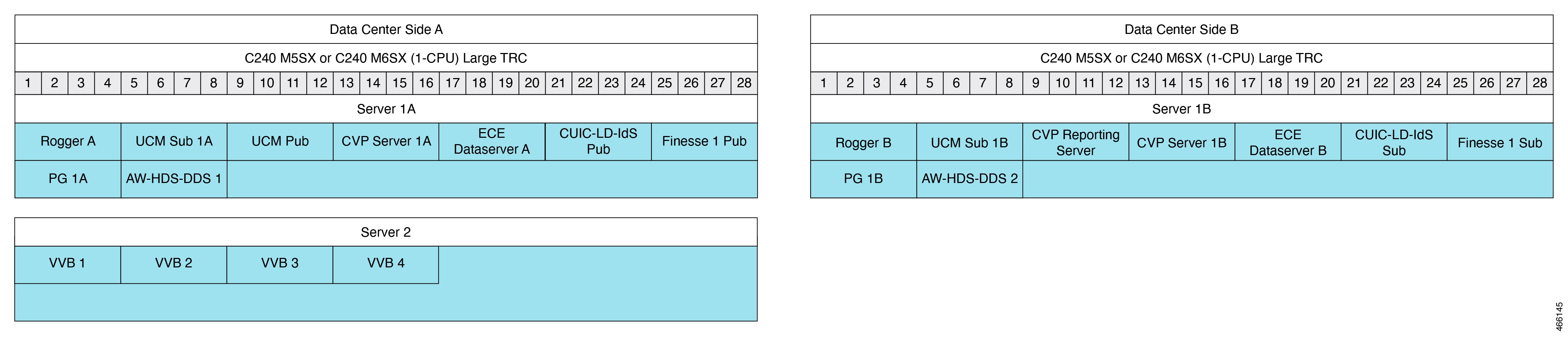
This table lists the specifications for VMs.
Table 3. VM Specifications for 2000 Agent Reference Design
VM | vCPU | MHz | vRAM | vDisk 1 | vDisk 2 | vDisk 3 |
|---|---|---|---|---|---|---|
Rogger | 4 | 5000 | 6 | 80 | 150 | |
Unified CM | 4 | 7200 | 8 | 110 | ||
Unified CVP Server | 4 | 3000 | 12 | 250 | ||
Unified CVP Reporting Server | 4 | 1800 | 6 | 80 | 438 | |
| ECE Dataserver 1 | 4 | 4000 | 20 | 80 | 50 | 300 |
CUIC-LD-IdS | 4 | 5500 | 16 | 200 | ||
AW-HDS-DDS | 4 | 5000 | 16 | 80 | 750 | |
PG | 2 | 4000 | 6 | 80 | ||
Finesse | 4 | 5000 | 10 | 146 | ||
VVB | 4 | 9000 | 10 | 146 |
1 For the latest VM specifications, see the row for 400 agents in the Virtualization for Enterprise Chat and Email page at https://www.cisco.com/c/dam/en/us/td/docs/voice_ip_comm/uc_system/virtualization/virtualization-enterprise-chat-email.html.Table 4. Total VM Requirements for 2000 Agent Reference Design
Server | vCPU | MHz | vRAM | vDisk |
|---|---|---|---|---|
Data Center Site A | 34 | 45900 | 102 | 2386 |
Data Center Site B | 30 | 40500 | 100 | 2648 |
Server 2 | 16 | 36000 | 40 | 584 |
Support on the Cisco HX220c-M5SX TRC Server
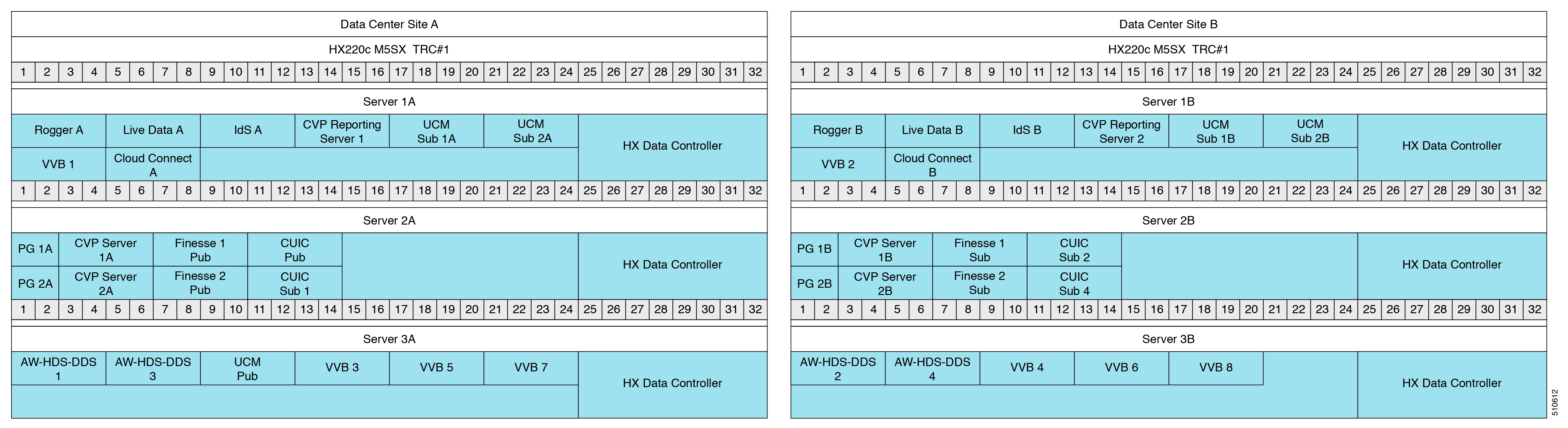
This figure shows the base layout of the components in a 2000 Agent Reference Design on Cisco HX220c-M5SX TRC server.
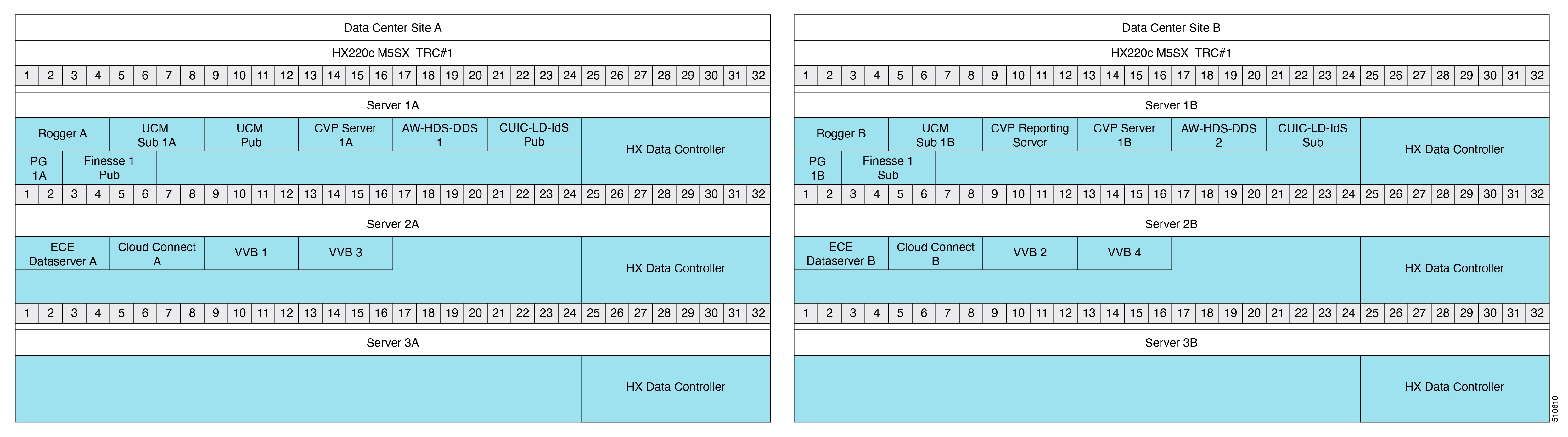
This table lists the specifications for VMs.
Table 5. VM Specifications for 2000 Agent Reference Design
VM | vCPU | MHz | vRAM | vDisk1 | vDisk2 | vDisk 3 |
|---|---|---|---|---|---|---|
HX Data Controller | 16 | 10800 | 48 | |||
Rogger | 4 | 5000 | 6 | 80 | 150 | |
Unified CM | 4 | 7200 | 8 | 110 | ||
Unified CVP Server | 4 | 3000 | 12 | 250 | ||
Unified CVP Reporting Server | 4 | 1800 | 6 | 80 | 438 | |
ECE Dataserver 2 | 4 | 4000 | 20 | 80 | 50 | 300 |
CUIC-LD-IdS | 4 | 5500 | 16 | 200 | ||
AW-HDS-DDS | 4 | 5000 | 16 | 80 | 750 | |
PG | 2 | 4000 | 6 | 80 | ||
Finesse | 4 | 5000 | 10 | 146 | ||
VVB | 4 | 9000 | 10 | 146 | ||
Cloud Connect | 4 | 6000 | 10 | 146 |
2 For the latest VM specifications, see the row for 400 agents in the Virtualization for Enterprise Chat and Email page at https://www.cisco.com/c/dam/en/us/td/docs/voice_ip_comm/uc_system/virtualization/virtualization-enterprise-chat-email.html.Table 6. Total VM Requirements for 2000 Agent Reference Design
Server | vCPU | MHz | vRAM | vDisk |
|---|---|---|---|---|
Data Center Site 1A | 46 | 52700 | 130 | 1956 |
Data Center Site 1B | 46 | 47300 | 128 | 2364 |
Data Center Site 2A | 32 | 38800 | 98 | 868 |
Data Center Site 2B | 32 | 38800 | 98 | 868 |
4000 Agent Reference Designs
All contact center enterprise solutions support the 4000 Agent Reference design on the following TRC servers:
Cisco UCS C240 M5SX Large
Cisco UCS C240 M6SX Large
Cisco HX220c-M5SX
This model adds servers to scale up from the 2000 Agent Reference Design.
| Note | You can only deploy two AW-HDS-DDS per data center site in the 4000 Agent Reference Design. In larger solutions, you use a combination of HDS-DDS and AW-HDS. |
- Support on the Cisco UCS C240 M5SX and Cisco UCS C240 M6SX TRC Servers
- Support on the Cisco HX220c-M5SX TRC Server
Support on the Cisco UCS C240 M5SX and Cisco UCS C240 M6SX TRC Servers
| Important | If you plan to upgrade to 12.x on Cisco UCS C240 M4SX servers, make the following changes to your servers and VM layouts:
|
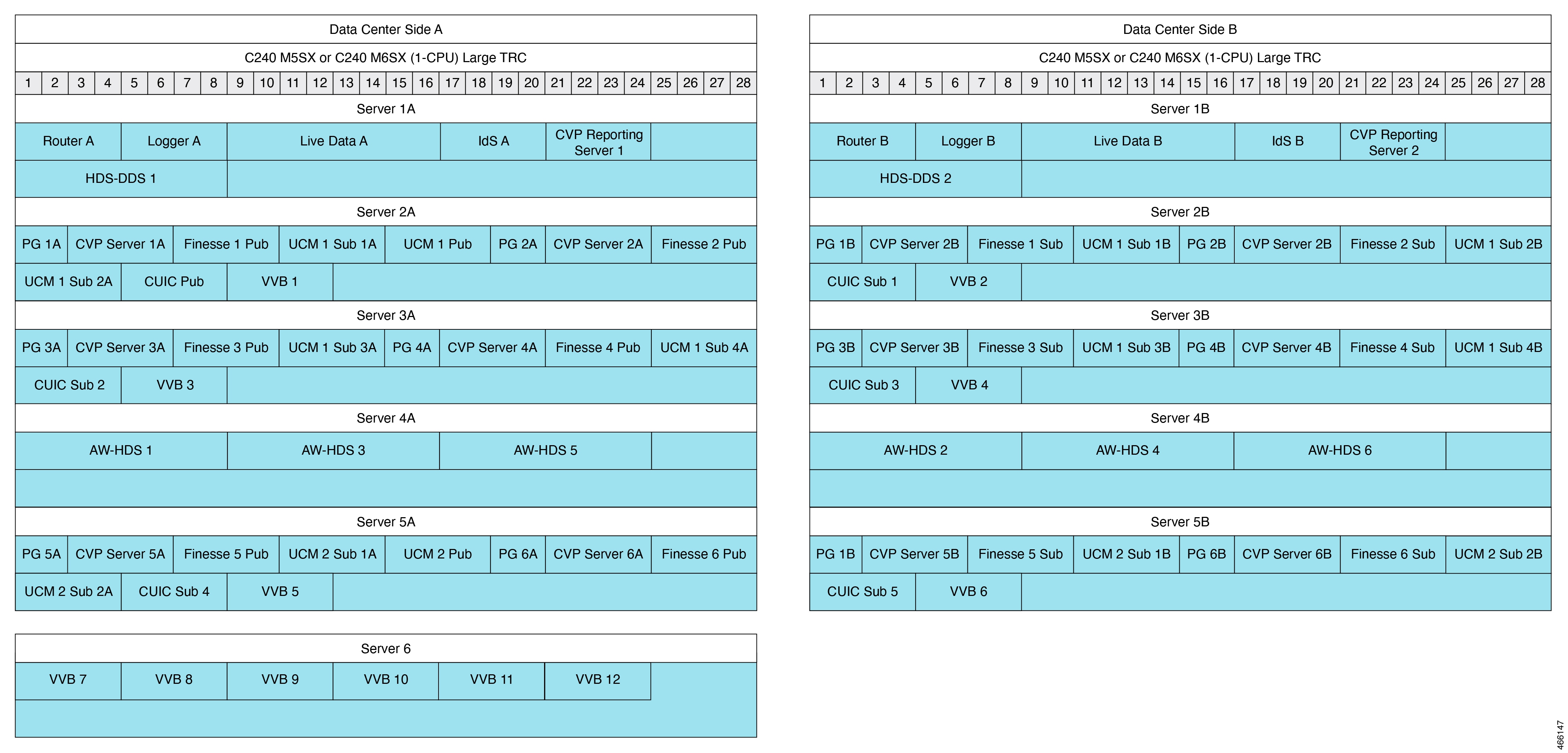
This figure shows the base layout of the components in a 4000 Agent Reference Design on Cisco UCS C240 M5SX and Cisco UCS C240 M6SX TRC servers.
Figure 3. 4000 Agent Reference Design Model
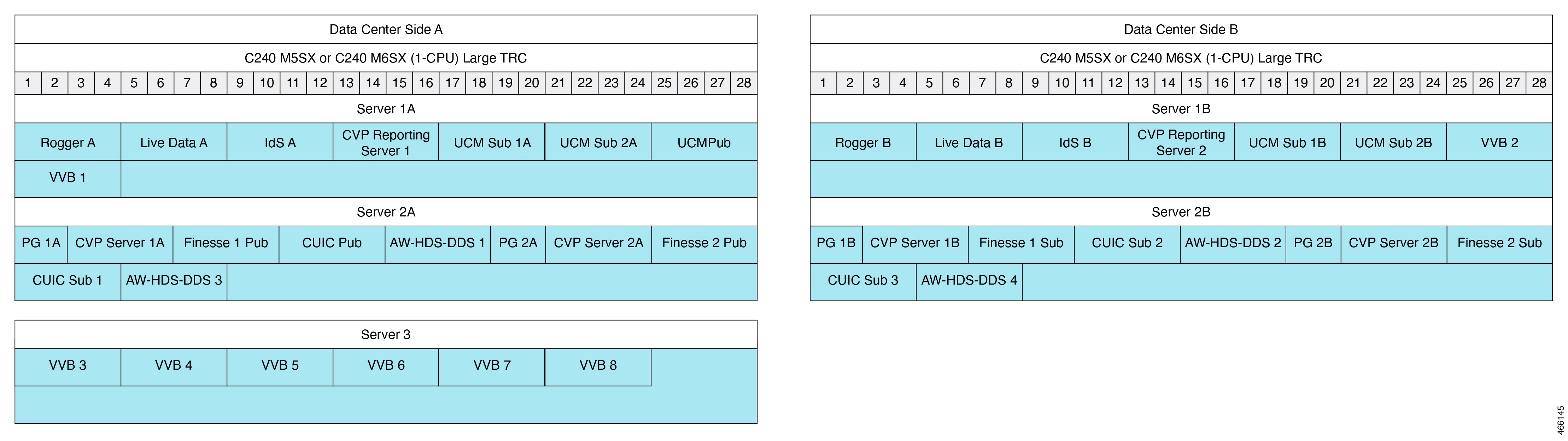
This table lists the specifications for VMs.
Table 7. VM Specifications for 4000 Agent Reference Design
VM | vCPU | MHz | vRAM | vDisk 1 | vDisk 2 | |
|---|---|---|---|---|---|---|
Rogger | 4 | 5000 | 6 | 80 | 150 | |
Live Data | 4 | 5500 | 30 | 146 | ||
IdS | 4 | 1500 | 10 | 146 | ||
Unified CVP Reporting Server | 4 | 1800 | 6 | 80 | 438 | |
Unified CM | 4 | 7200 | 8 | 110 | ||
PG | 2 | 4000 | 6 | 80 | ||
Unified CVP Server | 4 | 3000 | 12 | 250 | ||
Finesse | 4 | 5000 | 10 | 146 | ||
Unified Intelligence Center | 4 | 3600 | 16 | 200 | ||
AW-HDS-DDS | 4 | 5000 | 16 | 80 | 750 | |
VVB | 4 | 9000 | 10 | 146 |
Table 8. Total VM Requirements for 4000 Agent Reference Design
Server | vCPU | MHz | vRAM | vDisk |
|---|---|---|---|---|
Data Center Site A - Server 1A | 32 | 44400 | 86 | 1516 |
Data Center Site B - Server 1B | 28 | 37200 | 78 | 1406 |
Data Center Site A - Server 2A | 36 | 45000 | 120 | 2762 |
Data Center Site B - Server 2B | 36 | 45000 | 120 | 2762 |
Server 3 | 24 | 54000 | 60 | 876 |
Support on the Cisco HX220c-M5SX TRC Server
This figure shows the base layout of the components in a 4000 Agent Reference Design on Cisco HX220c-M5SX TRC server.
Figure 4. 4000 Agent Reference Design Model
This table lists the specifications for VMs.
Table 9. VM Specifications for 4000 Agent Reference Design
VM | vCPU | MHz | vRAM | vDisk 1 | vDisk 2 | |
|---|---|---|---|---|---|---|
HX Data Controller | 16 | 10800 | 48 | |||
Rogger | 4 | 5000 | 6 | 80 | 150 | |
Live Data | 4 | 5500 | 30 | 146 | ||
IdS | 4 | 1500 | 10 | 146 | ||
Unified CVP Reporting Server | 4 | 1800 | 6 | 80 | 438 | |
Unified CM | 4 | 7200 | 8 | 110 | ||
PG | 2 | 4000 | 6 | 80 | ||
Unified CVP Server | 4 | 3000 | 12 | 250 | ||
Finesse | 4 | 5000 | 10 | 146 | ||
Unified Intelligence Center | 4 | 3600 | 16 | 200 | ||
AW-HDS-DDS | 4 | 5000 | 16 | 80 | 750 | |
VVB | 4 | 9000 | 10 | 146 | ||
Cloud Connect | 4 | 6000 | 10 | 146 |
Table 10. Total VM Requirements for 4000 Agent Reference Design
Server | vCPU | MHz | vRAM | vDisk |
|---|---|---|---|---|
Data Center Site A - Server 1A | 48 | 54000 | 136 | 1552 |
Data Center Site B - Server 1B | 48 | 54000 | 136 | 1552 |
Data Center Site A - Server 2A | 48 | 50800 | 152 | 1932 |
Data Center Site B - Server 2B | 48 | 50800 | 152 | 1932 |
Data Center Site A - Server 3A | 24 | 44200 | 70 | 1958 |
Data Center Site B - Server 3B | 20 | 37000 | 62 | 1848 |
12000 Agent Reference Designs
This Reference Design for a contact center enterprise solution supports 12000 agents on the following TRC servers:
Cisco UCS C240 M5SX Large
Cisco UCS C240 M6SX Large
Cisco HX220c-M5SX
This model adds servers to scale up from the 4000 Agent Reference Design.
- Support on the Cisco UCS C240 M5SX and Cisco UCS C240 M6SX Large TRC servers
- Support on the Cisco HX220c-M5SX TRC Server
- Reporting Users in the 12000 Agent Reference Design Model
Support on the Cisco UCS C240 M5SX and Cisco UCS C240 M6SX Large TRC servers
The following figure shows the base layout of the components in a 12000 Agent Reference Design on Cisco UCS C240 M5SX and Cisco UCS C240 M6SX Large TRC servers.
Figure 5. 12000 Agent Reference Design Model
This table lists the specifications for VMs.
Table 11. VM Specifications for 12000 Agent Reference Design
VM | vCPU | MHz | vRAM | vDisk 1 | vDisk 2 |
|---|---|---|---|---|---|
Router | 4 | 4000 | 8 | 80 | |
Logger | 4 | 6000 | 8 | 80 | 500 |
Live Data | 8 | 16500 | 30 | 146 | |
IdS | 4 | 1500 | 10 | 146 | |
Unified CVP Reporting Server | 4 | 1800 | 6 | 80 | 438 |
HDS-DDS | 8 | 17500 | 16 | 80 | 500 |
AW-HDS | 8 | 17500 | 16 | 80 | 500 |
PG | 2 | 4000 | 6 | 80 | |
Unified CVP Server | 4 | 3000 | 12 | 250 | |
Finesse | 4 | 5000 | 10 | 146 | |
Unified CM | 4 | 7200 | 8 | 110 | |
Unified Intelligence Center | 4 | 3600 | 16 | 200 | |
VVB | 4 | 9000 | 10 | 146 |
Table 12. Total VM Requirements for 12000 Agent Reference Design
Server | vCPU | MHz | vRAM | vDisk |
|---|---|---|---|---|
Data Center Site A - Server 1A | 32 | 47300 | 78 | 2050 |
Data Center Site B - Server 1B | 32 | 47300 | 78 | 2050 |
Data Center Site A - Server 2A | 40 | 60100 | 106 | 1628 |
Data Center Site B - Server 2B | 36 | 52900 | 98 | 1518 |
Data Center Site A - Server 3A | 36 | 52900 | 98 | 1518 |
Data Center Site B - Server 3B | 36 | 52900 | 98 | 1518 |
Data Center Site A - Server 4A | 24 | 52500 | 48 | 1740 |
Data Center Site B - Server 4B | 24 | 52500 | 48 | 1740 |
Data Center Site A - Server 5A | 40 | 60100 | 106 | 1628 |
Data Center Site B - Server 5B | 36 | 52900 | 98 | 1518 |
Server 6 | 24 | 54000 | 60 | 876 |
Support on the Cisco HX220c-M5SX TRC Server
This figure shows the base layout of the components in a 12000 Agent Reference Design on Cisco HX220c-M5SX TRC server.
Figure 6. 12000 Agent Reference Design Model
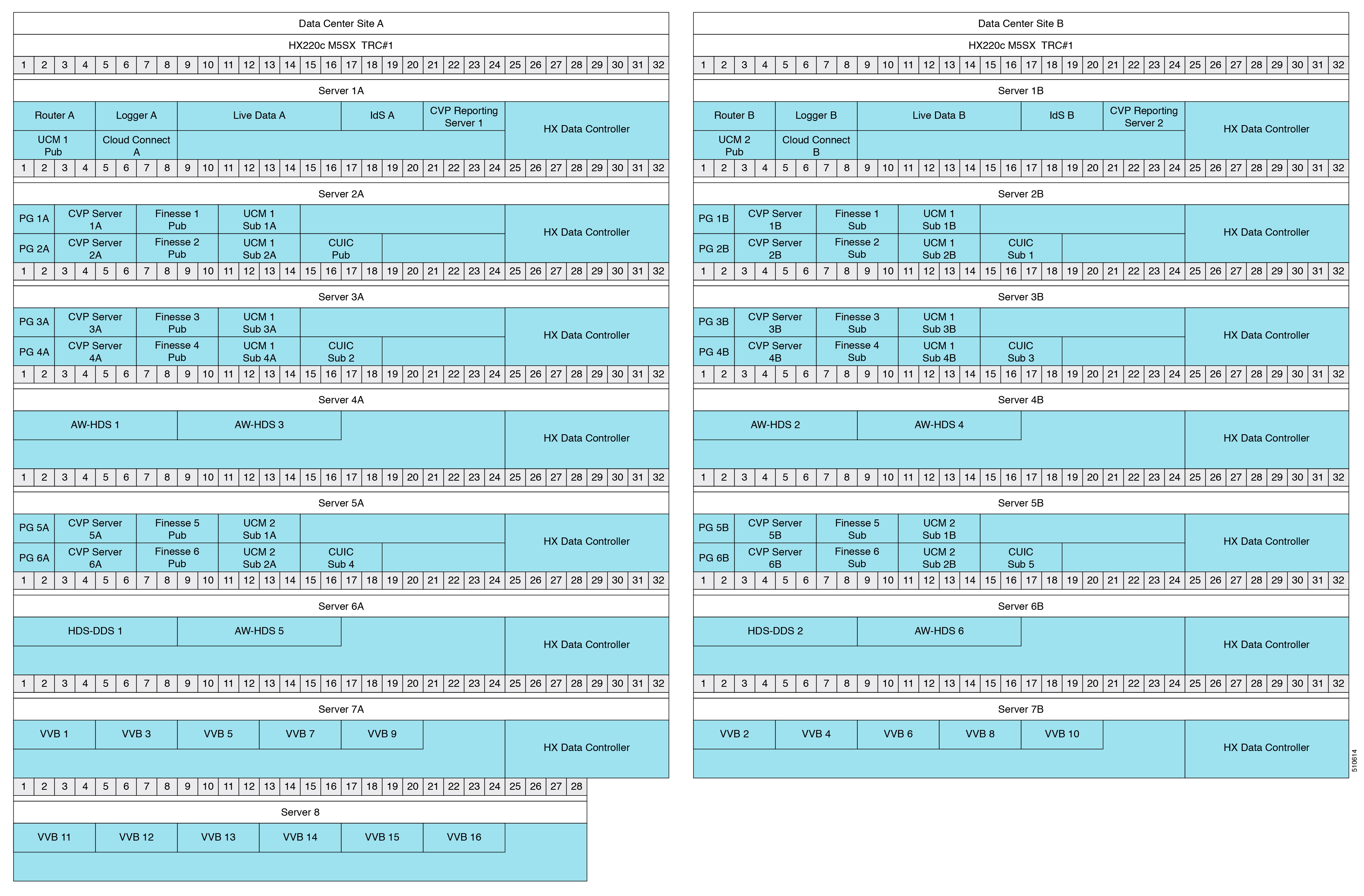
This table lists the specifications for VMs.
Table 13. VM Specifications for 12000 Agent Reference Design
VM | vCPU | MHz | vRAM | vDisk 1 | vDisk 2 |
|---|---|---|---|---|---|
HX Data Controller | 16 | 10800 | 48 | ||
Router | 4 | 4000 | 8 | 80 | |
Logger | 4 | 6000 | 8 | 80 | 500 |
Live Data | 8 | 16500 | 30 | 146 | |
IdS | 4 | 1500 | 10 | 146 | |
Unified CVP Reporting Server | 4 | 1800 | 6 | 80 | 438 |
HDS-DDS | 8 | 17500 | 16 | 80 | 420 |
AW-HDS | 8 | 17500 | 16 | 80 | 500 |
PG | 2 | 4000 | 6 | 80 | |
Unified CVP Server | 4 | 3000 | 12 | 250 | |
Finesse | 4 | 5000 | 10 | 146 | |
Unified CM | 4 | 7200 | 8 | 110 | |
Unified Intelligence Center | 4 | 3600 | 16 | 200 | |
VVB | 4 | 9000 | 10 | 146 | |
Cloud Connect | 4 | 6000 | 10 | 146 |
Table 14. Total VM Requirements for 12000 Agent Reference Design
Server | vCPU | MHz | vRAM | vDisk |
|---|---|---|---|---|
Data Center Site A - Server 1A | 48 | 53800 | 128 | 1726 |
Data Center Site B - Server 1B | 48 | 53800 | 128 | 1726 |
Data Center Site A - Server 2A | 48 | 54700 | 136 | 1372 |
Data Center Site B - Server 2B | 48 | 54700 | 136 | 1372 |
Data Center Site A - Server 3A | 48 | 54700 | 136 | 1372 |
Data Center Site B - Server 3B | 48 | 54700 | 136 | 1372 |
Data Center Site A - Server 4A | 32 | 45800 | 80 | 1160 |
Data Center Site B - Server 4B | 32 | 45800 | 80 | 1160 |
Data Center Site A - Server 5A | 48 | 54700 | 136 | 1372 |
Data Center Site B - Server 5B | 48 | 54700 | 136 | 1372 |
Data Center Site A - Server 6A | 32 | 45800 | 80 | 1080 |
Data Center Site B - Server 6B | 32 | 45800 | 80 | 1080 |
Data Center Site A - Server 7A | 36 | 55800 | 98 | 730 |
Data Center Site A - Server 7B | 36 | 55800 | 98 | 730 |
Server 8 | 24 | 54000 | 60 | 876 |
Reporting Users in the 12000 Agent Reference Design Model
AW-HDS 3, AW-HDS 4, AW-HDS 5, and AW-HDS 6 in Servers 4A and 4B, are optional to support more than 400 reporting users. Servers 5A and 5B are optional to support more than 8000 agents. Servers 6A and 6B are optional to support more than 400 reporting users.
This Reference Design supports a maximum of six CUIC VMs and six AW-HDS VMs, three VMs on each site. This limit can accommodate a maximum of 1200 reporting users. If one site shuts down, the remaining site can only support 600 reporting users on its three nodes.
Contact Director
Only Unified CCE supports the Contact Director reference design. The Contact Director distributes incoming calls to other contact center instances. The targets can be Unified CCE instances or Unified ICM instances that connect to third-party contact centers. The Contact Sharing feature uses a Contact Director to distribute incoming contacts to a maximum of 3 Unified CCE instances.
Figure 7. Contact Director Solution with Two Unified CCE Target Instances
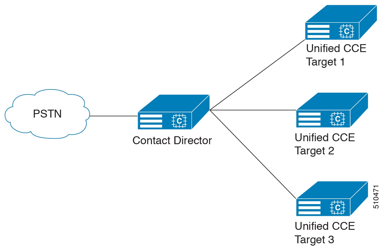
For information on the Contact Sharing feature, see the Cisco Unified Contact Center Enterprise Features Guide at http://www.cisco.com/c/en/us/support/customer-collaboration/unified-contact-center-enterprise/products-feature-guides-list.html.
Topologies for Reference Designs
The Contact Center Enterprise Reference Designs also define the allowed topologies for your deployment. The deployment topology consists of where you install the VMs for your data center and how your agents connect to the data center. This figure shows the basic topologies that you can use in a Reference Design.
Figure 8. Reference Design Topologies
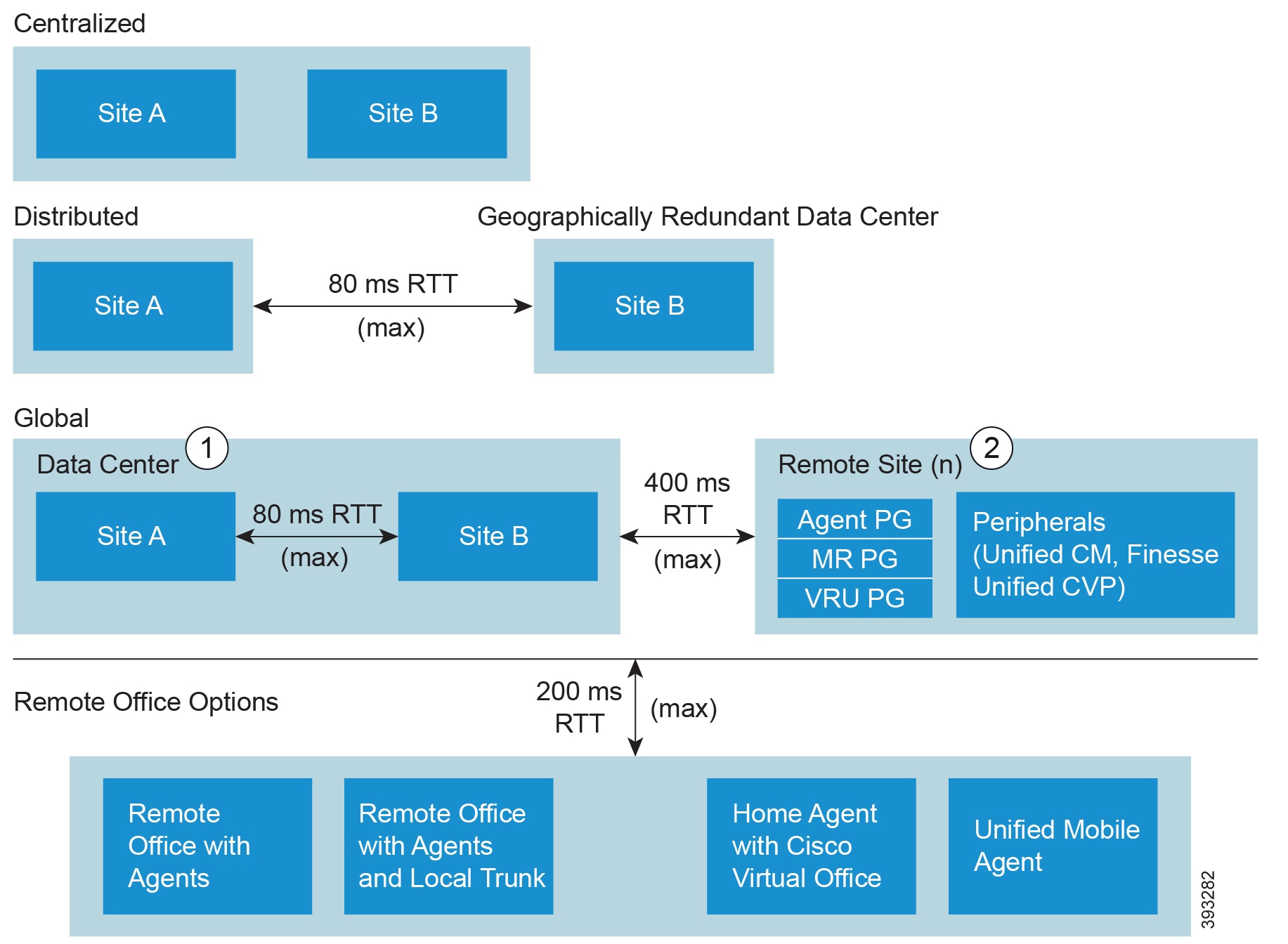
The Main Site can use either a Centralized or a Distributed topology.
A Remote Site can be geographically colocated with the Main Site.
The Reference Designs allow the following topologies:
Topology | Description | ||||
|---|---|---|---|---|---|
Centralized | You host both sites of the redundant components in the same physical data center. Even when they are on the same LAN, the maximum round-trip time between the two sites is 80 ms. The data center includes the core contact center components and Unified CM. | ||||
Distributed | You host each site of the redundant components in a different geographical location. Distributed sites allow you to keep running on the other site if one site fails. You can also handle routing without sending a contact to a site in a different geographical region. The maximum round-trip time between the two sites is 80 ms. | ||||
Global | You have a centralized or distributed main site. You also have a remote site that is generally in a different geographical location. The remote site gives you local access in that geographic region. The remote site allows you to handle your global work load without creating another contact center instance. The remote site requires a separate Unified CM cluster and a separate Cisco Finesse cluster if the RTT from the data center is greater than 80 ms. The maximum round-trip time between the main site and remote sites is 400 ms.
This topology fits the outsourcer model where the outsourcer has a separate peripheral gateway and a corresponding peripheral.
|
The Reference Designs allow the following methods for connecting your agents to a site:
Remote Office Topology | Description |
|---|---|
Remote Office with Agents | A contact center office with agent workstations that connects to a site through a WAN router. The voice termination is at the site. All contacts go through the site first and then to the agents. |
Remote Office with Agents and Local Trunk | A contact center office with a connection to the local PSTN. Contacts come in on the local trunk and the local gateway passes them to the data center for routing. |
Home Agent with Broadband - Cisco Virtual Office (CVO) | An agent at a remote location with a VPN connection to a site. The agent has a Cisco IP Phone and a Cisco Finesse desktop. The agent can optionally use a Cisco Virtual Office (CVO) router for a permanent VPN connection. |
Unified Mobile Agent | An agent who uses a PSTN phone. |
| Note | The maximum allowed round-trip time between any remote office and the data center is 200 ms. |
 Feedback