Cisco Business Access Point Administration Guide, Version 10.8.1.0
Bias-Free Language
The documentation set for this product strives to use bias-free language. For the purposes of this documentation set, bias-free is defined as language that does not imply discrimination based on age, disability, gender, racial identity, ethnic identity, sexual orientation, socioeconomic status, and intersectionality. Exceptions may be present in the documentation due to language that is hardcoded in the user interfaces of the product software, language used based on RFP documentation, or language that is used by a referenced third-party product. Learn more about how Cisco is using Inclusive Language.
These mounting instructions describe the steps for mounting supported Cisco Business Wireless series access points in several
configurations, including on a suspended ceiling, on a hard ceiling or wall, on an electrical or network box, and above a
suspended ceiling.
Preparing the AP for Installation
Before you mount and deploy your access point, we recommend that you perform a site survey (or use the site planning tool)
to determine the best location to install your access point.
You should have the following information about your wireless network available:
Access point locations.
Access point mounting options: on a wall or a ceiling only.
Note
You can mount the access point above a suspended ceiling but you must purchase additional mounting hardware. For additional
information, see mounting and grounding sections for individual access point models in the later sections.
Access points mounted in a building’s environmental airspace must be powered using PoE to comply with safety regulations.
The CBW140AC, CBW240AC, CBW145AC access point models are powered through PoE and the CBW142ACM model is directly plugged into
an AC source.
Cisco recommends that you make a site map showing access point locations so that you can record the device MAC addresses from
each location and return them to the person who is planning or managing your wireless network.
Mounting CBW140AC/240AC
Cisco Business Wireless 140AC/240AC access points can be mounted in several configurations; on a suspended ceiling, on a hard
ceiling or wall, or in the plenum air space above a suspended ceiling. You can mount the AP on an electrical or network box.
Note
When mounting the AP in the plenum air space or above a suspended ceiling, it should be mounted on a vertical wall or with
the face of the AP (having the status LED) directed downwards.
Mounting the Hardware
Mounting hardware for access points consists of brackets, which connect to the bottom of the access point, and ceiling grid
clips, which connect the bracket to a suspended ceiling. The bracket that you need depends on the mounting location for the
access point. The ceiling grid clip that you need depends on the type of suspended ceiling where you need to install the access
point. You don’t need ceiling grid clips if you are mounting the access point to a hard-surface ceiling or a wall.
Mounting Brackets
The standard mounting hardware supported by the AP is listed in the following table:
Table 1. Bracket for Mounting the Access Points
Parts
Part Number
Description
Bracket
It has 4 expansion screws. You can fasten the bracket to the wall or ceiling using these expansion screws.
74-123953-01
Mounting bracket for ceiling and wall. It also includes the Ceiling Grid Clip.
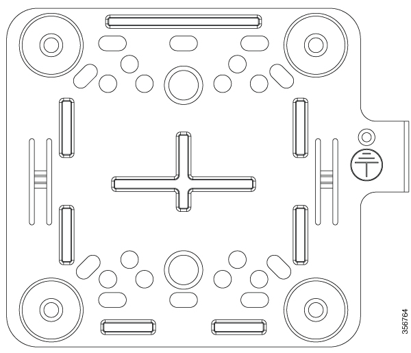
The following figure shows the low-profile bracket installed on an access point.
Figure 1. Low-Profile Mounting Bracket
Ceiling Grid Clip
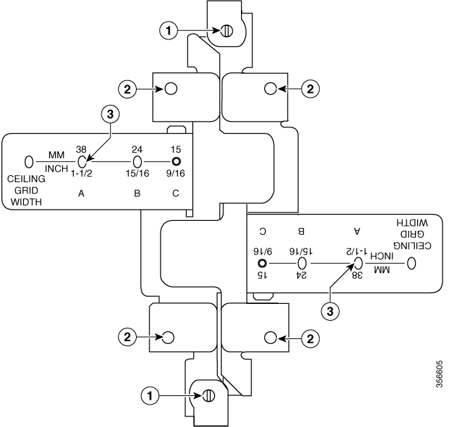
You use a ceiling grid clip (included) to mount an access point on a suspended ceiling.
Figure 2. Ceiling Grid Clip
Image Number
Description
1
Locking screws
2
Bracket screw holes
3
T-rail width detents (A, B, or C)
Mounting an Access Point Below a Suspended Ceiling
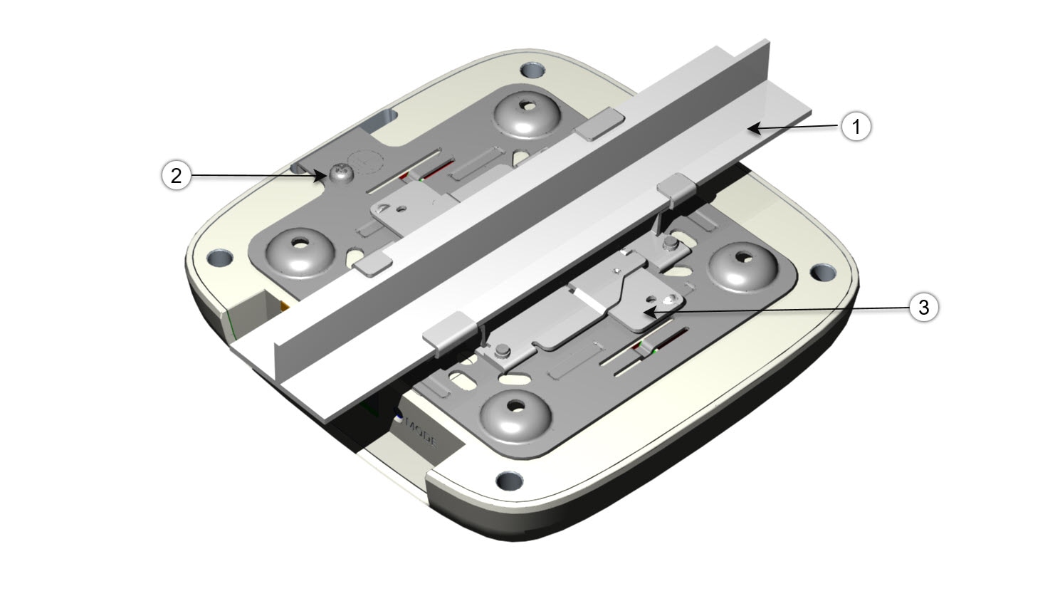
Follow these steps to mount the access point below a standard or recessed suspended ceiling. The following figure shows an
access point mounted on a T-rail ceiling rail using a ceiling grid clip.
Figure 3. Suspended Ceiling Mounting Details
Image Number
Description
1
Ceiling T-rail
2
Grounding point
3
Ceiling grid clip
To mount the access point below a suspended ceiling, do the following:
Decide where you want to mount the access point on your suspended ceiling.
Open the ceiling grid clip completely.
Place the ceiling grid clip over the T-rail and close it to the appropriate detent (A, B, or C).
Use a screwdriver to tighten the two ceiling grid clip locking screws to prevent the clip from sliding along the T-rail.
Observe the ceiling grid clip width detent letter (A, B, or C) that corresponds to the T-rail width.
Align the corresponding holes (A, B, or C) on the mounting bracket over the mounting holes on the ceiling grid clip.
Hold the mounting bracket and insert a 6-32 x 1/4 in. screw into each of the four corresponding holes (A, B, or C) and tighten.
If necessary, drill or cut a cable access hole in the ceiling tile large enough for the Ethernet cable.
(Optional) Use the ground screw to ground the access point to a suitable building ground. See Grounding an Access Point for general grounding instructions.
Connect the Ethernet cable to the access point.
Align the bracket feet over the keyhole mounting slots on the access point.
Gently slide the access point onto the mounting bracket until it clicks into place.
Fasten the AP to the bracket using the M2 x 5.5mm Torx security screw. Cover it with the mylar label.
Mounting an Access Point on a Hard Ceiling or a Wall
This procedure describes the steps required to mount the access point on a ceiling constructed of 3/4-in (19.05-mm) or thicker
plywood using #8 fasteners using the mounting bracket.
Note
Access points with integrated antennas perform best when the access point is mounted on horizontal surfaces such as a table
top or ceiling. For advanced features such as voice, location, and rogue access point detection, ceiling mounting is strongly
recommended. However, for smaller areas such as conference rooms, kiosks, transportation environments, or hot-spot usage where
data coverage is the primary concern, the unit may be wall mounted using wall anchors or screws.
To mount the access point on a solid ceiling or wall, do the following:
Use the mounting bracket as a template to mark the locations of the mounting holes on the bracket.
Caution
Be sure to mark all four locations. To ensure a safe and secure installation, make sure you are using adequate fasteners and
mount the access point using no less than four fasteners.
Do not use plastic wall anchors or the keyhole slots on the mounting bracket for ceiling installations. When mounting the
access point on a hard ceiling, use four fasteners capable of maintaining a minimum pullout force of 20 lbs (9 kgs).
Use a #29 drill (0.1360-in. [3.4772 mm]) bit to drill a pilot hole at the mounting hole locations you marked.
Note
The pilot hole size varies according to the material and thickness you are fastening. Cisco recommends that you test the material
to determine the ideal hole size for your mounting application.
(Optional) Drill or cut a cable access hole large enough for the Ethernet cable and the building ground wire.
(Optional) Use the ground screw to attach the building ground wire to the mounting bracket. See Grounding an Access Point for general grounding instructions.
Position the mounting bracket mounting holes (with indents down) over the pilot holes.
Insert a fastener into each mounting hole and tighten.
Connect the Ethernet cable to the access point.
Align the bracket feet over the keyhole mounting slots on the access point.
Gently slide the access point onto the mounting bracket keyhole slots until it clicks into place.
Fasten the AP to the bracket using the M2 x 5.5mm Torx security screw. Cover it with the mylar label.
Mounting an Access Point to a Network or Electrical Box
To mount an access point to a network box or an electrical box, do the following:
Position the universal mounting bracket over the existing network or electrical box and align the bracket mounting holes with
the box holes.
Hold the mounting bracket in place and insert a 6 x 32 x 1/4-in pan head screw into each of the mounting holes and tighten.
(Optional) Use the ground screw to attach the building ground wire to the mounting bracket. See Grounding an Access Point for general grounding instructions.
Connect the Ethernet cable to the access point.
Align the bracket feet over the keyhole mounting slots on the access point.
Slide the access point onto the optional mounting bracket until it clicks into place.
Fasten the AP to the bracket using the M2 x 5.5mm Torx security screw. Cover it with the mylar label.
Mounting an Access Point Above a Suspended Ceiling
Using third-party accessories (not offered by Cisco) you can mount an access point above a suspended ceiling.
Note
Install access points above ceiling tiles only when mounting below the ceiling is not an option. Mounting access points above
the ceiling can interfere with advanced wireless LAN features that depend on uniform coverage, such as voice and location.
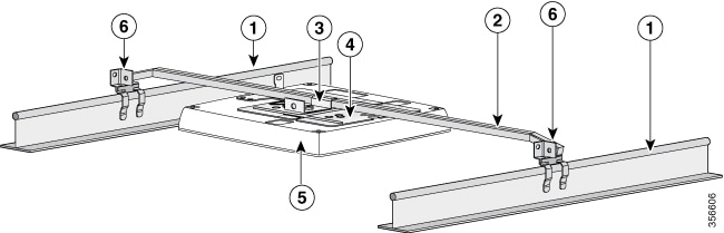
Figure 4. T-Bar Grid Mounting Bracket Parts
Image Number
Description
1
Suspended ceiling T-rail
2
Box hanger
3
Box hanger clip
4
Mounting bracket
5
Access point
6
T-rail clip
To mount the access point above a suspended ceiling, do the following:
Remove a ceiling tile adjacent to the mounting location.
Fasten the access point mounting bracket to the box hanger using the clip or screws provided with the box hanger kit.
Connect the Ethernet cable to the access point.
Align the bracket feet over the keyhole mounting slots on the access point.
Slide the access point onto the mounting bracket until it clicks into place.
Attach the T-rail clips on each end of the T-bar box hanger to the ceiling rails. Make sure the clips are securely attached
to the T-rails.
Fasten the AP to the bracket using the M2 x 5.5mm Torx security screw. Cover it with the mylar label.
Replace the ceiling tile.
Mounting CBW145AC
The Cisco Business Wireless 145AC access points can be mounted in several configurations—on a suspended ceiling, on a hard
ceiling or wall, or in the plenum air space above a suspended ceiling and on a electrical junction box using the spacer.
Table 2. Access Point Mounting Options
Parts
Part Number
Description
Bracket
74-112728-01 (Included)
Mounting the AP directly on a Wall
Mounting the AP on an Electrical Junction Box
Mounting the AP on a Wall using the Spacer
AIR-AP1815W-KIT= (Optional, not included)
Spacer Kit: Includes spacer and RJ-45 jumper cable.
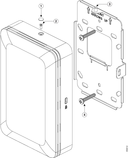
Figure 5. Mounting AP on a Wall
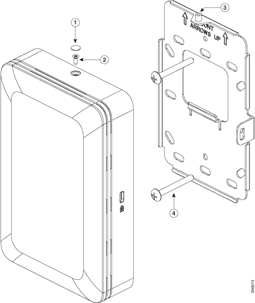
Mounting the AP on 74-112728-01 and Electrical Junction Box
To mount the CBW145AC-B on the junction box, do the following:
Fasten the wall-mount bracket (74-112728-01) to the wall, using two M3.5X32mm screws. Ensure that the side having the Mount Arrows Up label is facing outwards, and the bracket is oriented vertically as indicated by the arrows.
Connect the PoE cable from the junction box to the PoE port on the rear of the device. If there is a second Ethernet cable
in the junction box, it can be connected to the Pass-Through port on the rear of the device and accessed using the Pass-Through
port on the bottom of the device.
Note
If you are unable to connect a PoE cable to the port on the back of the AP, then:
On the back of the AP, use an RJ45 jumper cable to connect the PoE port to the Pass-Through port. This jumper cable is available
as part of the spacer kit AIR-AP1815W-KIT=.
Connect the PoE supply cable to the Pass-Through port on the base of the AP.
This connection sends power internally from the Pass-Through port on the base, to the Pass-Through port on the back, and then
though the jumper cable into the PoE port on the back.
Mount the AP onto the wall-mount bracket. For this, align the AP with the bracket and then offset the AP around ¼ inch above
the bracket.
Fasten the AP to the bracket using the M2 x 5.5mm Torx security screw. Cover it with the mylar label.
Image Number
Description
1
Mylar label for covering Torx security screw slot
2
M2 x 5.5mm Torx security screw
3
Screw hole on the wall-mount bracket for the security screw
4
Two M3.5 x 32mm screws for fastening the bracket to the wall
Figure 6. Mounting the AP on an Electrical Junction Box
Mounting the AP on a Wall using the Spacer box
To mount the AP on a wall, using a spacer box, do the following:
Fasten the spacer box (AIR-AP1815W-KIT= ) to the wall, using four M3.5 x 32mm screws. Ensure that the side having the Mount Arrows Up label is facing outwards, and the box is oriented vertically as indicated by the arrows.
Fasten the wall-mount bracket (74-112728-01) to the spacer box, using two M3X8mm tapping screws. Ensure that the side having
the Mount Arrows Up label is facing outwards, and the bracket is oriented vertically as indicated by the arrows.
Connect the power and network cables to the AP.
If you are unable to connect a PoE cable to the port on the back of the AP, then do the following:
On the back of the AP, use an RJ45 jumper cable to connect the PoE port to the Pass-Through port. This jumper cable is available
as part of the spacer kit AIR-AP1815W-KIT=spacer kit.
Connect the PoE supply cable to the Pass-Through port on the base of the AP.
Note
The punch-out holes on the spacer box (AIR-AP1815W-KIT) can be used for routing cables. However, an RJ45 connector will not
fit through these holes. If this is required, you must first route a cable through the hole and then crimp an RJ45 connector
on to the cable.
This connection sends power internally from the Pass-Through port on the base, to the Pass-Through port on the back, and then
though the jumper cable into the PoE port on the back.
Mount the AP onto the wall-mount bracket. For this, align the AP with the bracket and then offset the AP around ¼ inch above
the bracket.
Fasten the AP to the bracket using the M2 x 5.5mm Torx security screw. Cover it with the mylar label
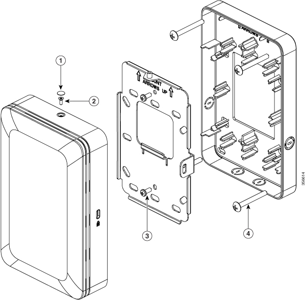
Figure 7. Mounting the AP on a Wall using the Spacer
Image Number
Description
1
Mylar label for covering Torx security screw slot.
2
M2 x 5.5mm Torx security screw.
3
M3X8mm tapping screws for fastening the wall-mount bracket to the spacer.
4
M3.5 x 32mm screws for fastening the spacer to the wall.
Mounting CBW141AC
The access point can be placed/mounted in a horizontal position, on a horizontal surface such as a table.
To ensure the best RF coverage for your access point, place your access point in an area as close to the wireless clients
as possible and practical to do so. If the Internet source or gateway router is in a remote area, position your access point
away from metal obstructions.
Areas to avoid or places that may result in reduced range or performance are as follows.
In a basement of a multi-story home, as the signals must penetrate many walls.
Near large obstructions that can block the radio signals. Avoid areas like metal cabinets or refrigerators.
On the floor under a metal desk or other dense or conductive objects.
The AP is powered using 44 to 57 VDC power via the VDC port, using Cisco Power Adapter. The PoE-Out port provides 802.3af
Class 0 (15.4W) power.
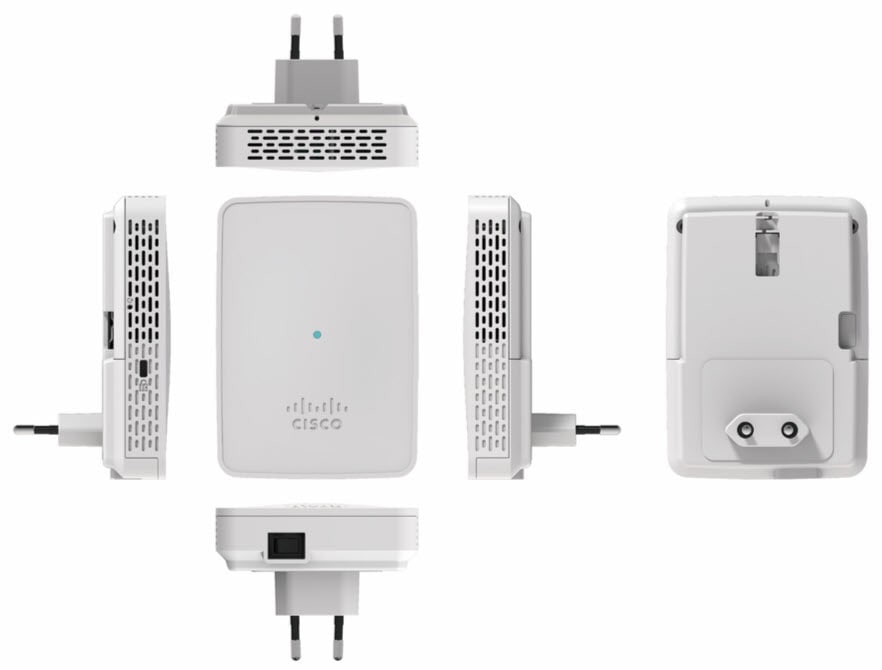
Mounting CBW142AC
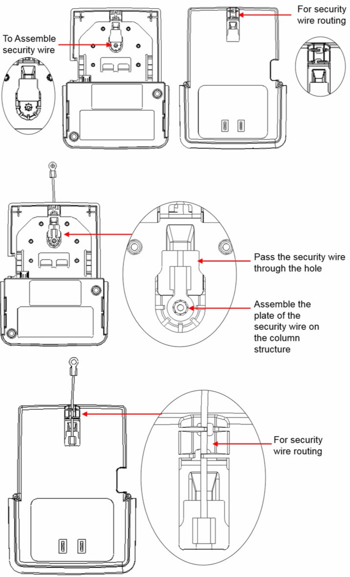
You can additionally secure the AP by fastening the security wire to the wall or desk.
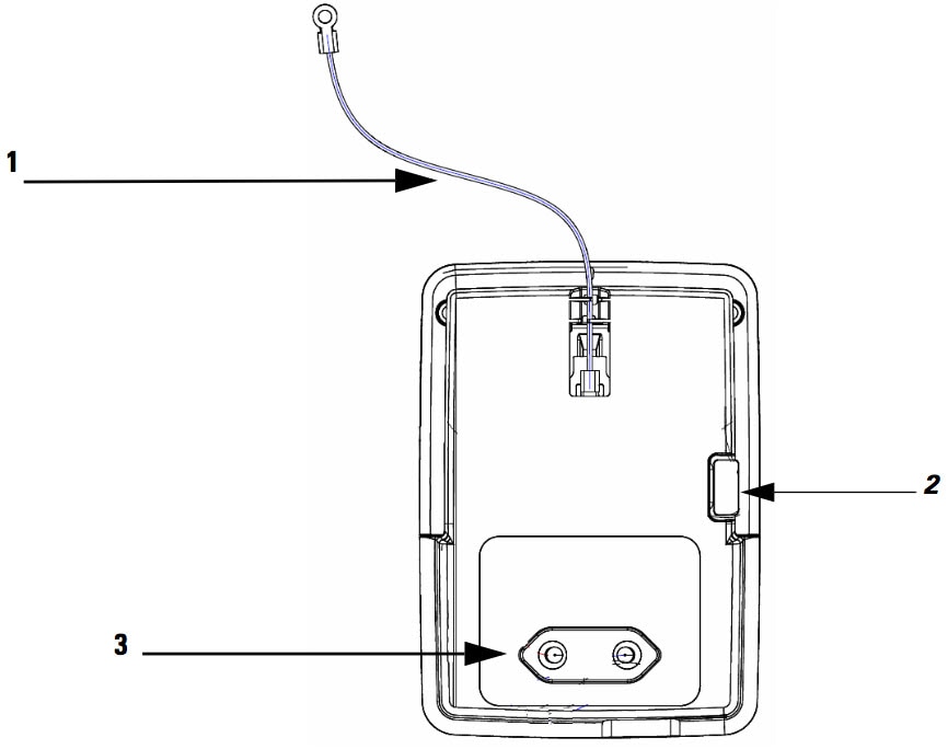
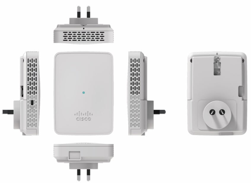
Figure 8. Back of the AP – With AC Adapter Module
The assembling of front and rear views are shown below:
Image Number
Description
1
Security wire which can be used to secure the AP by fastening it to the wall.
3
EU-specification AC adapter module CBW142
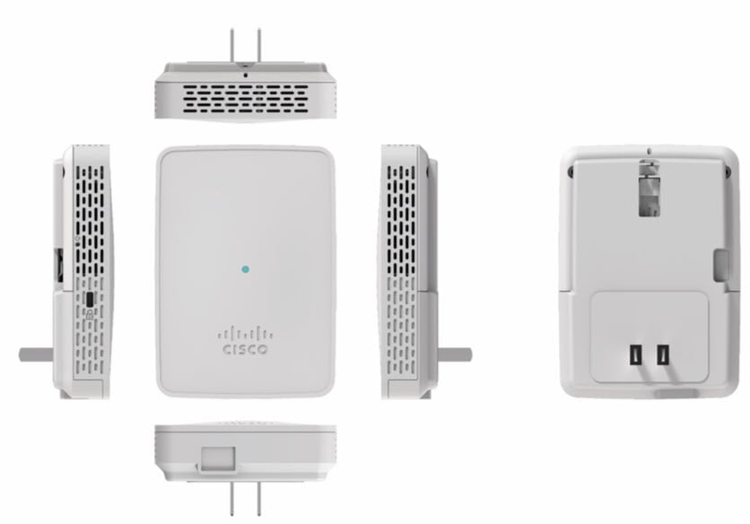
The AC adapter module/cradle provided differs in design according to regional power supply standards.
Figure 9. Assembling and Routing the Security Wire – Front and Rear Views
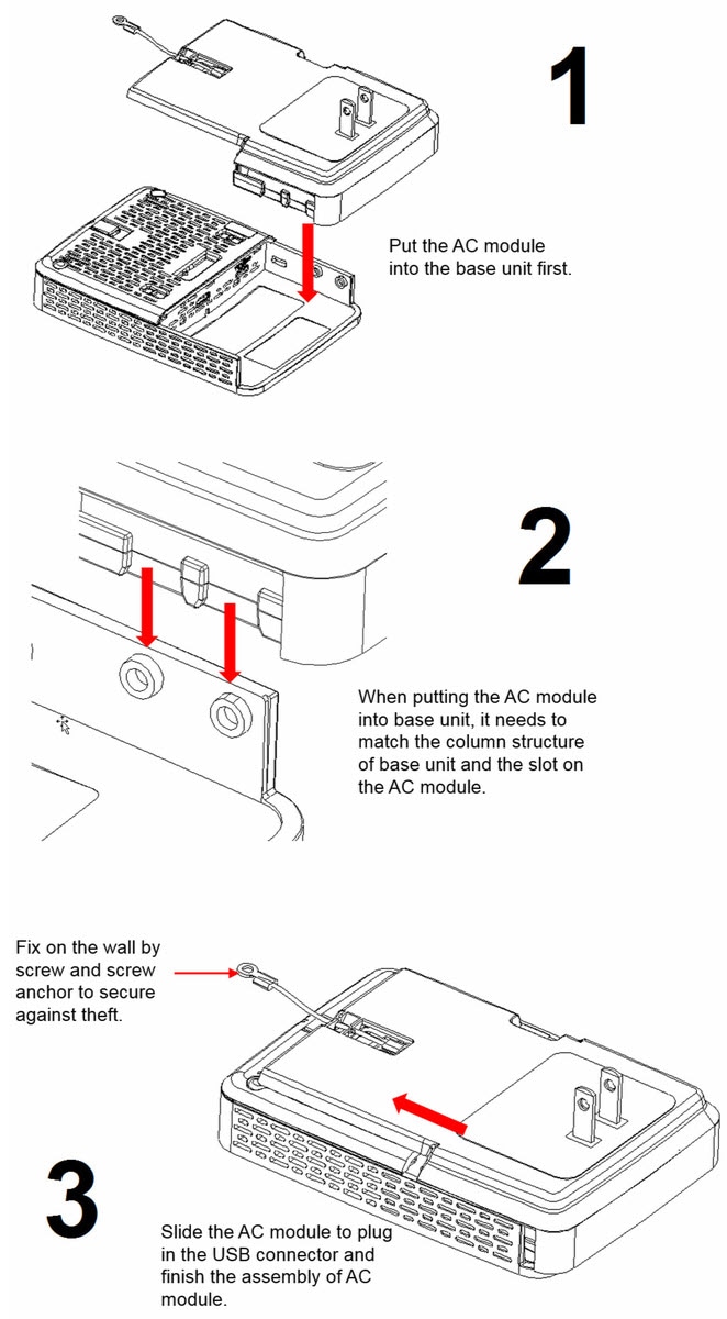
The assembling of AC unit with base module is shown below:
Figure 10. Assembling AC module with Base Unit
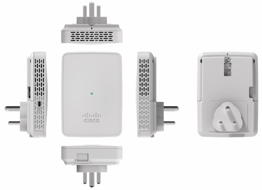
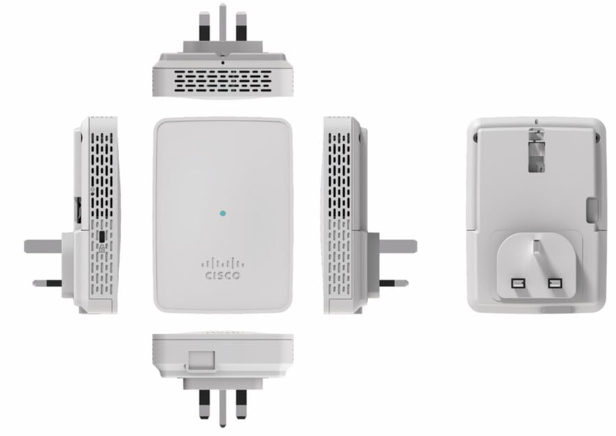
The various assembling models for CBW142AC is as follows:
Assembling model for AU Region
Assembling model for CN Region
Assembling model for EU Region
Assembling model for SA Region
Assembling model for UK Region
CBW142AC: AC power from a wall socket power outlet, through the AC Adapter module, providing 120~240VAC, 50~60Hz power.
The AC adapter module also functions as a mounting cradle, thereby mounting the sensor on a wall socket power outlet mounted
with the help of a stabilizer.
Mounting CBW143AC
The CBW143AC series access points can be mounted, in a vertical orientation, on a wall or desk. The mounting is done using
the wall-mount bracket 74-123954-01.
Item
Part Number
Description
Bracket
74-123954-01 (Included)
Mounting the AP directly on a Wall
To mount the AP on a wall:
Identify the location for mounting the AP.
Use the wall-mount bracket 74-123954-01, as a template to mark the screw-hole locations for fastening the bracket to the wall.
At the marked locations, drill a hole into the wall.
Fasten the 74-123954-01 to the wall using two 18mm expansion screws.
Hold the back of the AP against the wall, above the bracket, and then slide the AP down onto the bracket, till it clicks into
place. The hooks on the bracket will click into the recesses on the back of the AP.
Proceed with connecting the data and power cables.
The AP can be powered using the following power sources and devices only:
AC power, using the AC-USB adapter, supplying 5V DC, 1.5A power.
The USB ports are located on the base of the AP.
The CBW143AC can also be powered using PoE (802.3af) supplied through the Ethernet port from a power injector.
Note
Cisco recommends that you use only the Cisco supplied AC-USB adapter, for powering the AP through the USB port. Other power
supply devices which do not meet the specifications of the Cisco supplied device, can cause silent reboots or crashes.
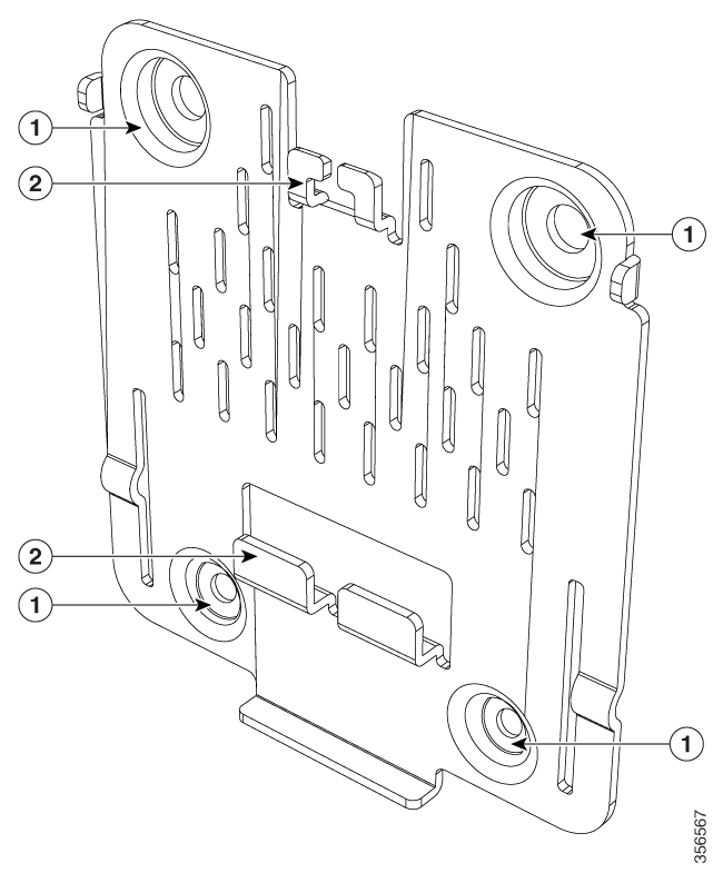
Figure 11. Wall and Desk Mounting Bracket 74-123954-01
Image Number
Description
1
Screw holes for fastening the bracket to the wall
2
Hooks which click into the recesses on the back of the AP for mounting the AP on the bracket
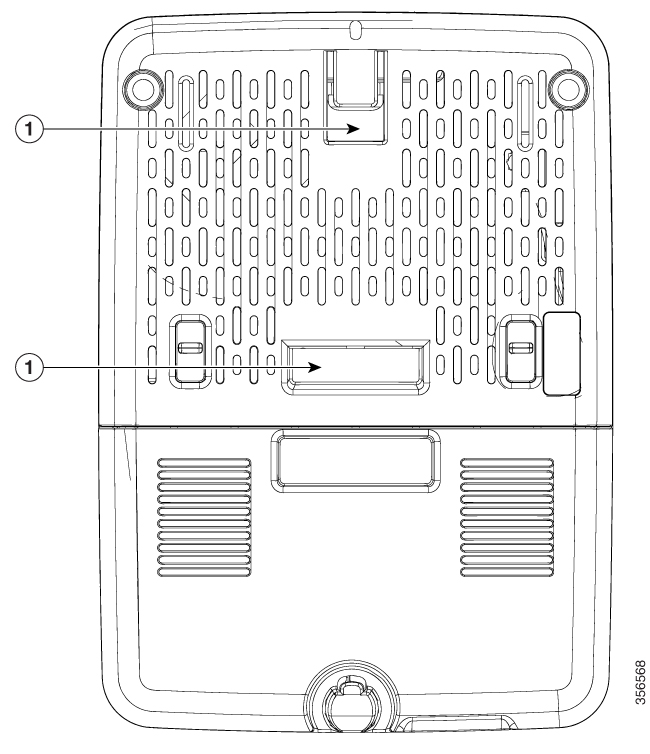
Figure 12. Back of the AP
Image Number
Description
1
Recesses on the back of the AP into which the hooks on the wall-mount bracket slide and click into place.
The CBW145AC, CBW141ACM, CBW142ACM, and CBW143ACM devices support a Kensington-style lock.
The location of the Kensington lock slot is shown in the Quick Start guides provided with the device.
Grounding an Access Point
Grounding is not always required for indoor installations because Cisco Business Access Points are classified as low-voltage
devices and do not contain internal power supplies. We recommend that you check your local and national electrical codes to
see if grounding is a requirement.
Although grounding is not mandatory for indoor access points, it is required in certain scenarios. It has been observed that
an ungrounded indoor access point that is mounted too close to an electromagnetic source of interference (such as a fluorescent
light that is on) may reboot suddenly or suffer hardware damage. This occurs even if the indoor AP is in close proximity to
the electromagnetic source of interference, and not touching the source. Grounding the corresponding access point or the mounting
bracket helps prevent this issue from occurring. We recommend that a certified electrical technician verify whether your installation
requires grounding.
If grounding is required in your area or you wish to ground your access point, do the following:
Procedure
Step 1
Find a suitable building grounding point as close to the access point as possible.
Step 2
Connect a user-supplied ground wire to the building grounding point. The wire should be a minimum of #14AWG assuming a circuit
length of 25 ft (30.5 cm). Consult your local electrical codes for additional information.
Step 3
Route the ground wire to the access point.
Step 4
Attach the wire to a suitable grounding O-ring lug.
To locate the grounding point on the device, refer this image.
Step 5
Crimp or solder the wire to the lug.
Step 6
Insert the grounding post screw into the O-ring lug and install it on the mounting bracket as shown in the figure above.
Step 7
Use a Phillips screwdriver to tighten the ground screw.


 Feedback