Installing the Controller in Oracle Cloud Infrastructure

Installing Controller on Oracle Cloud Infrastructure

Cisco Catalyst Wireless Controller for Cloud on Oracle Cloud Infrastructure

The IOS XE based Cisco Catalyst Wireless Controller for Cloud (C9800-CL) sets the standard for Infrastructure as a Service (IaaS) secure wireless network services with Oracle Cloud Infrastructure (OCI). C9800-CL combines the advantages and flexibility of an OCI public cloud with the customization and feature-richness that customers usually experience on-prem deployments.

Scalability

C9800-CL scales up to x Access Points and y clients with features like Zero Touch AP provisioning, High Availability, Application Visibility and Control, and more. Here, x and y values depend on the capacity of the instance.

The following are the scale values for small, medium, and large instances:

Small: 1000 APs and 10,000 clients

Medium: 3000 APs and 32,000 clients

Large: 6000 APs and 64,000 clients

OCI Compute Instances

OCI Compute service helps you provision and control the compute hosts, referred to as instances. You can create instances according to your specific compute and application needs.

When you create an instance, you can

  • securely connect to it from your own computer

  • reboot it

  • connect and disconnect storage volumes, and

  • shut it down permanently when it is no longer needed.

Any changes made to the local drives of the instances are lost when you terminate it. Any saved changes to volumes attached to the instance are retained.
Figure 1. OCI Networking

Supported Cloud Deployment Scenarios

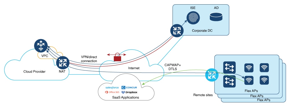
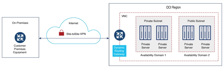
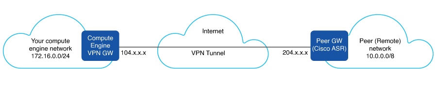
The Cisco Catalyst Wireless Controller for Cloud supports the following deployment scenario:

  • Virtual Private Network (VPN) between the AP locations and the Public Cloud

  • Connect directly to the Public IP of the controller in the cloud

Guidelines and Limitations

  • Cisco Catalyst 9800 Wireless Controller for Cloud - Ultra-Low Profile is not supported on public cloud.

  • Only a single interface (single VNIC) is supported

  • Only FlexConnect mode (Local Switching) is supported.

  • The following operations will lock you out of the OCI instance, without a possible recovery:

    • Deleting SSH credentials

    • Providing incorrect SSH credentials

    • Deleting interface configuration

    • Providing incorrect interface configuration

    • Configuring write erase

Virtual Cloud Network

The Virtual Cloud Network (VCN) in Oracle Cloud Infrastructure (OCI) serves as the foundational networking layer, like the Virtual Private Cloud (VPC) offered by other cloud services. A VCN is similar to a physical network which is virtualized within OCI.

With a VCN you can

  • establish a tailored and isolated network within Oracle's cloud environment

  • define the IP address space

  • set up subnetworks, and

  • manage traffic flow by configuring route tables and gateways, both within the VCN and to external destinations.

In OCI you can either create and assign a new VCN or use an existing VCN.

Figure 2. OCI Virtual Cloud Network

Creating a New VCN

You can create a VCN that is used by instances, load balancers, and other resources to connect to each other and to the internet. Create a new VCN manually or with the help of the VCN Wizard. The wizard maps default subnets and gateways for the VCN. If you use the manual option, you must manually create subnets and gateways, else you can use the defaults.

Create VCN using VCN Wizard

Procedure


Step 1

Choose OCI console > Networking > Virtual Cloud Networks.

Step 2

Click Start VCN Wizard.

Step 3

Click one of the following options:

  • Create VCN with Internet Connectivity: Creates a VCN with a public subnet that is connected through the Internet. It also creates a private subnet that connects to the Internet through the NAT gateway, and privately connects to the Oracle Services Network.
  • Add Internet Connectivity and Site-to-Site VPN to a VCN: Adds a site-to-site VPN between your on-premise network and a VCN you have selected.

Step 4

In the Configuration section, enter the VCN name.

Step 5

Map the VCN to the correct Compartment.

Step 6

In the Configure VCN section, enter the VCN IPv4 CIDR block.

Note

 
If you plan to peer this VCN with another VCN, the VCNs must not have overlapping CIDR blocks.

Step 7

Enter the IPv4 CIDR block for public and private subnets.

Step 8

In the Review and create window, verify the configuration details of the subnet and click Review and create.

Internet, NAT, and Service Gateways are created for the VCN. Default security lists and route tables are used. The rules added to the default security lists and the route tables are also displayed, which can be modified later.

Create a VCN Manually

Before you begin

For a manually created VCN, ensure that the following components or resources are availabe for Internet connectivity or connectivity to on-premise network:

  • Subnets – Private and Public

  • Internet Gateway

  • Security Lists

  • Route Tables

  • NAT Gateway

  • Service Gateway

Procedure


Step 1

Choose OCI console > Networking > Virtual Cloud Networks.

Step 2

Click Create VCN.

Step 3

In the Create a Virtual Cloud Network window, in the IPv4 CIDR Blocks field, enter the IPv4 CIDR block for the VCN.

Step 4

Click Create VCN.


What to do next

  • Create a public and private subnet

  • Create a security list

  • Create an internet gateway

  • Create a route table

  • Create a NAT gateway

  • Create a service gateway

Create Public and Private Subnets

Public Subnet

Create a public subnet in the Subnet Access option to allow all public IP addresses for instances deployed with this subnet.

Create a Public Subnet

For information and detailed steps about creating a public subnet, refer to Create a Public Subnet.

Private Subnet

Create a private subnet in the Subnet Access option to prohibit all public IP addresses for instances deployed with this subnet.

Create a Private Subnet

For information and detailed steps about creating a private subnet, refer to Create a Private Subnet.

Create a Security List

Security Lists

Security lists are virtual firewalls for the instances for which you can define ingress and egress rules that apply to all the VNICs in the subnet.

Create a Security List

For information and detailed steps about creating a security list, see Create a Security List.


Note


You can restrict access to your instance using the security lists, for security reasons. For example, if you want to permit only CAPWAP from a certain IP range, so that only those APs register with the controller, you must enable inbound and outbound rules for CAPWAP.


The following table lists the ports and protocols that may be enabled on the controller:

Ports

Protocols

UDP 5246/5247/5248 CAPWAP
TCP 22 SSH, SCP
TCP 21 FTP
ICMP Ping
UDP 161, 162 SNMP/SNMP traps
TCP 443/80 HTTPs/HTTP
TCP/UDP 49 TACACS+
UDP 53 DNS Server
UDP 1812/1645/1813/1646 Radius
UDP 123 NTP Server
UDP 514 Syslog

Create an Internet Gateway

Internet Gateway

An internet gateway is an optional gateway you can add to your VCN to enable direct connectivity to the internet. The gateway supports connections initiated from within the VCN (egress) and connections initiated from the internet (ingress). Resources that need to use the gateway for internet access must be in a public subnet and have public IP addresses. Resources that have private IP addresses can use a NAT gateway to initiate connections to the internet.

Create an Internet Gateway

For information and detailed steps about creating an internet gateway, refer to Create an Internet Gateway.

Create a Route Table

Route tables are lookup tables for the VCN to send traffic to the internet, the on-prem network, or to a peered VCN. They are like network routes. Intra-VCN within the subnets are handles by the local-routing of the VCNs. Route tables contain rules that have a certain priority for each. In case of overlapping ones, the prior one is chosen. For traffic that do not match any route, rules are dropped.

Create a Route Table

For information and detailed steps about creating a route table, see Create a Route Table.

Create a NAT Gateway

NAT Gateway

You can add a NAT gateway to your VCN to give instances in a private subnet access to the internet. Instances in a private subnet do not have public IP addresses. With the NAT gateway, they can initiate connections to the internet and receive responses, but not accept inbound connections initiated from the internet.

Create a NAT Gateway

For information and detailed steps about creating a NAT gateway, see Create a NAT Gateway.

Create a Service Gateway

Oracle Cloud Infrastructure (OCI) Service Gateway provides private and secure access to multiple Oracle cloud services simultaneously from within a virtual cloud network (VCN) or an on-premise network through a single gateway, without traversing the internet. Services accessed through their public IP address are routed through OCI Service Gateway rather than an internet gateway when exiting a VCN.

Create a Service Gateway

For information and detailed steps about creating a service gateway, refer to Create a Service Gateway.

Create a VPC Instance

Procedure


Step 1

Navigate to the OCI console and choose Compute > Instances.

Step 2

Click Create Instance.

Step 3

Enter the name of the instance.

Step 4

In the Create in compartment field, scroll and select the required compartment.

Step 5

In the Placement section, select the Availability domain.

Step 6

In the Image and shape section, choose the desired image for the instance.

Step 7

Click Select image.

Step 8

In the Browse all shapes section, select the Instance type and the Shape series.

Note

 
The shape series includes the processors, OCPUs, and the memory for the instance.

Step 9

Click Select shape.

Step 10

In the Primary VNIC information section, choose the Primary network.

Step 11

Choose public or private subnets.

Step 12

In the Primary VNIC IP addresses section, assign private and public IPv4 addresses.

Note


VNIC private and public IPV4 addresses can be either assigned automatically or manually.

Step 13

In the Add SSH keys section, select one of the following:

  • Generate a key pair for me
  • Upload public key files (.pub)
  • Paste public keys
  • No SSH keys

Step 14

Click either the Save private key or the Save public key button to download the keys for SSH access to the controller instance.

The instance moves to the Provisioning state and then moves to the Running state. When the instance comes up, go to the console details and select Console connection and create a local connection with the SSH keys.


Initial Setup of Controller Using a Wizard (GUI)

You can access the controller GUI by using the public IP of the VCN assigned in the NAT gateway. Since the instance is not configured, when you log in, you are redirected to the Day 0 window.

Procedure


Step 1

In the Configuration Setup Wizard, under the General Settings window, add and verify the following:

  1. Change the Hostname, if required, as the hostname from the initial configuration appears.

  2. Configure the correct Country, Date, and Time/Timezone.

  3. Add NTP/AAA severs, if required.

  4. Within the sub-section Wireless Management Settings, verify if the interface is mapped with the correct private IP address, same as that of the instance.

Step 2

In the Wireless Network Settings window, add a WLAN network.

Step 3

In the Advanced Settings window, complete the RF parameters such as the Client Density, RF Group Name, Traffic Type, and the Virtual IP Address.

Step 4

In the AP Certificate section, complete the following:

  1. In the General Certificate toggle field, choose YES.

  2. From the RSA Key-Size drop-down list, choose the required key-size.

  3. From the Signature Algorithm drop-down list, choose the required algorithm.

  4. In the Password field, set the AP certificate password for the APs to join the wireless controller.

    Note


    These parameters will be used to create a self-signed certificate on the wireless controller.

Step 5

Click Summary to review the configuration details.

Step 6

Click Finish.


The configuration and trust point are pushed to the device. The C9800-CL controller will not reboot. After 60 seconds, log in again, by entering the same credentials. The C9800-CL controller GUI Dashboard is displayed, where you can view the WLAN details.

Initial Setup of Controller

Procedure


Step 1

Connect to the controller console when the instance is provisioned and running.

The prompt for the initial configuration of the controller is displayed.

Step 2

Configure the Management Setup and the Wireless Setup through the initial configuration of the controller.

Step 3

Enable the credentials for the WebUI and HTTP, to access the GUI of the controller.


Enabling Public IP on the Controller

The controller has two types of IPs — Private IP and Public IP.

To enable the Wireless Management Interface with Public IP, complete the following:

Procedure

  Command or Action Purpose

Step 1

configure terminal

Example:

Device# configure terminal

Enters global configuration mode.

Step 2

wireless management interface interface-type interface-number

Example:

Device(config)# wireless management interface gigabit 1

Defines the management interface.

Here,

  • interface-type—Refers to the Gigabit interface.

  • interface-number—The interface number is 1.

Note


The Public cloud VM supports only the following:

  • Gigabit as the interface-type.

  • 1 as the interface-number.

Step 3

public-ip external-public-ip

Example:

Device(config-mgmt-interface)# public-ip x.x.x.x.

Defines the external Public IP (x.x.x.x).

Step 4

end

Example:

Device(config-mgmt-interface)# end

Returns to privileged EXEC mode.

Enabling CAPWAP Discovery to Respond Only with Public or Private IP

By default, the CAPWAP discovery response covers both private and public IP.

VPN Tunnel

With the help of the VPN tunnel, the APs can reach the wireless controller instance without exposing the network to internet.

Figure 3. VPN Tunnel

Create a VPC-VPN Connection

The wizard sets up Site-to-Site VPN between your on-premises network and the Oracle VCN. To provide a VPN access to a VPC instance using Site-to-Site VPN, the following elements are required:

  1. VCN with a private or public subnet

  2. Dynamic Routing Gateway (DRG) to be attached with the VCN

  3. Internet Gateway (IG)

  4. Security Lists

  5. Subnets to be mapped to the VPN

  6. Customer-Premises Equipment (CPE)

Procedure


Step 1

On the OCI Console, choose Networking > Customer connectivity > Site-to-Site VPN.

Step 2

Click the Start VPN Wizard button to create the Site-to-Site VPN.

Note

 
Click the Start VPN Wizard button to create the Site-to-Site VPN, or, click the Create IPSec connection button to do it manually.

Step 3

In the Create Site-to-Site VPN window, complete the following:

  1. Compartment: Choose the appropriate compartment VCN to which the Site-to-Site VPN should be mapped. Select a default compartment for all new resources.

  2. Virtual cloud network: Choose an existing VCN for this connection.

  3. Dynamic routing gateway: Create a new DRG or choose and existing DRG. To access your on-premises network, the VCN must be connected to a DRG.

  4. Internet gateway: Choose an already existing internet gateway. An internet gateway helps you to quickly connect to an instance in a public subnet in your VCN.

Step 4

Click Next.

The Subnets and security window is displayed.

Step 5

In the Subnets and security window,

  • Select existing security list: Choose the security list for each subnet you choose.
  • Create new security list: Create a new security list which contains the new security rules.

Step 6

Choose the subnets from the list and click Next.

Step 7

In the Site-to-Site VPN window, choose one Routing type.

  • BGP dynamic routing: The available routes are learned dynamically through BGP.
  • Static routing: Static routing requires you to manually provide the static routes for subnets in your on-premises network.
  • Policy based routing: The routes are static and not learned dynamically.

Step 8

In the Routes to your on-premises network field, add the IP addresses. This is necessary for the establishment of the VPN tunnel.

Tunnel 1 and Tunnel 2 are created, based on the IKE version and a Shared secret, the Oracle side and the CPE.

Note


Ensure that the tunnels are in the UP state, for the VPC-VPN connection to work.

Step 9

Click Next.

The Customer-premises equipment window is displayed.

Step 10

In the Customer-premises equipment window, select an existing CPE by choosing the Select existing option, or, create a new CPE by choosing the Create new option.

Step 11

Enter the CPE name and IP address.

Step 12

In the CPE vendor information section, choose the vendor and the platform or the version.

Step 13

Click Next.

The Review and create window is displayed.

Step 14

In the Review and create window, review the details.

Step 15

Click the Create VPN button.

The Provision successful message is displayed.

You can view the VPN solution summary after provisioning.

Step 16

In the CPE Configuration Helper window, enter the IPSec connection details or leave it as optional.

Step 17

Click Create Content to get the configurations of the CPE.

You can view the VPN details in the VPN Solution Summary. The IPSec connection will be established after the CPE is configured correctly.

Troubleshooting - Controller on the Oracle Cloud Infrastructure

  • When the instance is launched, it would take around 8 - 9 minutes before it becomes reachable. Check the status of all the components of the VCN and the ensure that the instance is in Running state.

  • Configuration Issues:

    • The memory allocated for the instance should be equivalent to the required minimum for the instance to be provisioned properly.

    • Upload the bootable custom images properly to the OCI console for the instance to use it.

  • System Reachability Issues:

    • Correct use of key-pair for SSH or VCN access.

    • Controller misconfiguration.

    • Verify the rules in the Security Lists of the VCN. Use ssh -w to debug the SSH access to the controller.

  • AP Join Issues:

    • Reachability of APs to the public or private IP of the controller instance.

    • Wrong auth-token.

    • Generation of the management trust points for the controller.

  • VPC-VPN Issues:

    • Wrong shared secret.

    • Misconfiguration of the on-premises router.

    • Configuration of wrong route rules.