Policy Enforcement
Points
Overview
A Policy Enforcement Point, or PEP, is a component of policy-based management that might be a network access system (NAS). PEPs are not limited to NAS devices however.
Consider, when a user tries to access a file on a network or server that uses policy-based access management, the PEP describes the user's attributes to other entities on the system. The PEP gives the Policy Decision Point (PDP) the job of deciding whether or not to authorize the user based on the description of the user's attributes. Applicable policies are stored on the system and are analyzed by the PDP. The PDP makes it's decision and returns the decision. Then, the PEP lets the user know whether or not they have been authorized to access the requested resource.
Policy Enforcement Point Tree
Upon installation of Cisco Policy Suite, the Policy Enforcement Points tree under Reference Data tab resembles this.

Consult your Cisco Technical Representative for configuring a custom site.
Adding a Policy Enforcement Point
This section covers the following topics:
- Generic Radius Device Pool
- ISG Pools
- ASR9K PEP Configuration
- ASR5K PEP Configuration
- MAG PEP Configuration
- iWAG PEP Configuration
- Cisco WLCs
Generic Radius Device Pool
This example shows you how to add a Generic RADIUS device as a policy enforcement point. Your PEP may be different, but you can easily follow this example.

Defining a Policy Enforcement Point
Editing a Policy Enforcement Point
| Step 1 | Login to Policy Builder GUI. |
| Step 2 | Go to Reference Data tab > Policy Enforcement Points. |
| Step 3 | Select the device pool that holds your device. |
| Step 4 | Make your changes to the Device Pool window. |
| Step 5 | Save your work to the local directory by clicking on the diskette icon or CTRL+S. |
| Step 6 | If you are ready to commit these changes to the version control software select . |
Removing a Policy Enforcement Point
At times in building out your Policy Suite deployment, or perhaps due to network reconstruction, you may want to remove a device or a device pool.
To remove the entire node, highlight the node in the tree, and then click the red X at the top.

To delete an individual instance from the pool, perform the following steps:
| Step 1 | From the PB main screen, click Reference Data tab > Policy Enforcement Points. |
| Step 2 | Scroll through the tree on the left until you find the pool or device you want to delete. |
| Step 3 | To delete a device that is part of a pool, find the device pool and the device in the device table. |
| Step 4 | Select the
device and click
Remove.
 |
Example - Generic Radius Device Pool Configuration
The following example shows the sample configuration for generic radius device policy enforcement point. Here CoA Disconnect Template is configured with required Radius service template configured with required AVP's and an IP address is added at Devices table with Shared Secret and CoA Shared Secret. If the shared secrets are not configured in Devices table then it will use the default shared secretes configured above the table for all the devices listed in Devices table.

A sample configuration of CoA disconnect template is as shown below. This can be customized for different AVP's as required. We need to create this template in Reference Data tab > Radius Service Templates. We can create a group first and in that group we can add a Radius Service Template as shown below.

To make a sample call using Generic Radius PEP, perform the following steps:
| Step 1 | Configure the Radius plug-in in Reference Data tab > System > Plugin Configuration > Radius Configuration. | ||
| Step 2 | Configure the PEP as explained above for generic radius device pool. | ||
| Step 3 | Configure the domain as explained in Domain configuration, select the USuM Authorization type of authorization. | ||
| Step 4 | Configure the
service, this service must use the AccessAcceptConfiguration Template.
 | ||
| Step 5 | Add a subscriber in Control Center and Assign a service to it. | ||
| Step 6 | Make a radius
call with NAS IP same as provided in the devices table in Generic Radius Device
Pool.
|
ISG Pools
In the ISG Pools Summary window, click ISG Pool under Create Child to create a new ISG pool.
Enter the values for the required fields according to your requirement. An example is shown below.

In the Devices section, enter the Subnet or IP Range (CIDR notation). To add an IP Range, click Add. By default, the IP Range is 0.0.0.0. Edit the IP Range according to your requirement in the CIDR notation by clicking on the default value as shown below.

Enter the value for Shared Secret and CoA Shared Secret by selecting the blank row of the column respectively. An example is shown.
If the IP Range in one device definition overrides with any other IP Range or any IP Address in the same or other device definitions, the Policy Builder performs a validation check and displays suitable error messages against the Policy Enforcement Point, which has an overlapping IP range. Refer to the figure given below showing error messages due to IP Range overlap.

Configuration and Restrictions
Example - CPS Configuration for ISG Web-Auth Call Flow
Call Flow

Policy Builder Configuration
ISG Pool Configuration
Configure ISGs for policy enforcement points in CPS. The configuration includes configuring ISG IPs and any loopback interfaces used in ISG configuration. The shared secret needs to match with what is configured on ISG.

Most of the parameter are already covered in Generic Radius Device Pool and some of the new parameter defined in ISG Poll Configuration are as described in the following table:
|
Parameters |
Description |
|---|---|
|
Port Bundle Key Length |
The port-bundle length is used to determine the number of ports in one bundle. By default, the port-bundle length is 4 bits. |
|
Change Service Rule |
When a new service is to be activated this drop-down list tells what is the order to be followed: |
|
Accounting List |
This list is assigned to a client when it get successfully authenticated. |
|
Track WLC Locations |
This defines enhanced location mapping feature of the client. It will track the AP or SSID location of the client and will be stored as a location in the mongo radius database. |
RADIUS Templates Configuration
Radius service templates for ISG services are used to define all the services CPS will send access-accept for the requests received from ISG.
| Step 1 | Open Garden
services will allow subscribers to allow connections to open garden services
like DNS server before authentication is done. Cisco AVPAIRS are defined here
which will pushed to ISG to apply open garden access lists.
 |
| Step 2 | Define PBHK
services for subscriber sessions when ISG send the access-requests for the
subscribers. CPS will push the port bundle configuration to be enabled for
sessions.
 |
| Step 3 | Cisco redirect
services will define the AVpair values for redirect to a portal and
access-lists used for redirecting subscriber traffic.
 |
| Step 4 | Base Internet
services are defined here for subscribers when they get authenticated.
   |
Domain Configuration
| Step 1 | Configure a
Domain “web-auth” for the subscribers and authorizations based on session
Username and User Password. Set this domain as Default Domain.
 |
| Step 2 | Define locations
based on Framed IP location type.
 |
| Step 3 | Set Advanced
Rules For the MAC TAL.
 |
Service Configuration: Use Case Template
Read only Use Case Templates with their service configurations used in the Service configuration.


Service Configuration: Service Options
Service options based on above Use Case Templates.
| Step 1 | 3 min
service-option configuration of “Auto Register MAC Credential” Use Case
Template.
 |
| Step 2 | Base
Service-option Configuration of “Base ISG Service” Use Case Template.
  |
Service Configuration: Service
 |
Control Center Configuration
| Step 1 | Create
subscribers in USuM database and add service type applicable to the subscriber.
 |
| Step 2 | Select
Save
& Continue. Click
Services >
add.
 |
| Step 3 | Select a service
and click
Select to select a service from the available list of services.
 |
| Step 4 | For setting the
Credentials of the subscriber, click
Credentials >
edit.
 |
| Step 5 | Enter New Password and
Confirm
Password in the pop-up dialog box, then click
OK.
 |
| Step 6 | Click Save to save the configuration. |
ASR9K PEP Configuration
ASR9K PEP is used specifically for interfacing CPS with ASR9K devices. PEP configuration for ASR9K is same as Generic Radius device but there is one more additional parameter “Cache Account Session Id from Access Request”. This option will store the value coming in Account-Session-Id AVP in Session database within a session.

To make a sample call using ASR9K PEP, perform the following steps:
| Step 1 | Configure the radius plug-in in Reference Data tab > System > Plugin Configuration > Radius Configuration. |
| Step 2 | Configure the PEP as explained above for ASR9K. |
| Step 3 | Configure the domain as explained in Domains. For example, select USuM Authorization type of authorization. |
| Step 4 | Configure the
service, this service must use the ASR9K Templates listed below.
 |
| Step 5 | Add a subscriber in Control Center and assign a service to it. |
| Step 6 | Make a radius call with NAS IP same as provided in the devices table in ASR9K device table. |
ASR9K Call Flows
Portal Based Authentication


MAC-TAL

ASR5K PEP Configuration
ASR5K PEP is used specifically for interfacing CPS with ASR5K devices. PEP configuration for ASR5K is same as Generic Radius device. This does not have any additional parameters configuration. The need of having separate configuration is to differentiate the device type so that policy derivation/processing for ASR5K devices will be different. Service configuration for ASR5K needs to use the use case template of ASR5K.

To make a sample call using ASR5K PEP, perform the following steps:
| Step 1 | Configure the radius plug-in in Reference Data tab > System > Plugin Configuration > Radius Configuration. |
| Step 2 | Configure the PEP as explained above for ASR5K. |
| Step 3 | Configure the domain as explained in Domains chapter in this book. For example, select USuM Authorization type of authorization. |
| Step 4 | Configure the
service, this service must use the ASR5K Templates listed below.
 |
| Step 5 | Add a subscriber in Control Center and assign a service to it. |
| Step 6 | Make a radius call with NAS IP same as provided in the devices table in ASR5K device table. |
MAG PEP Configuration
MAG PEP is used specifically for interfacing CPS with MAG (Mobility Access Gateway). PEP configuration for MAG is same as Generic Radius Device Pool.

The following are the additional parameters used for MAG:
|
Parameter |
Description |
|---|---|
|
LMA Address |
LMA address will be sent to MAG in Access Accept response. |
|
MCC |
MCC and MNC is used to derive the partial MAC Address. |
|
MNC |
MCC and MNC is used to derive the partial MAC Address. |
|
Default Realm |
This default realm will be added to the UserId i.e. IMSI, User Id format will be encodedImsi@defaultRealm. Default Realm should be “wlan.mncxxx.mccxx.3gppnetwork.org”, otherwise “wlan.3gppnetwork.org”. |
|
Partial Mac for Mcc Mnc |
If this is checked, a partial MAC IMSI will be derived based on the MCC, MNC and MAC. |
To make a sample call using MAG PEP, perform the following the below steps:
| Step 1 | Configure the Radius plug-in in Reference Data tab > System > Plugin Configuration > Radius Configuration. |
| Step 2 | Configure the PEP as explained above for MAG. |
| Step 3 | Configure the domain as explained in Domains chapter in this book. For example, select the USuM Authorization type of authorization. |
| Step 4 | Configure the
service, this service must use the MAG Template listed below.
 |
iWAG PEP Configuration
iWAG PEP is used specifically for interfacing CPS with iWAG devices. PEP configuration for iWAG is same as Generic Radius device. This does not have any additional parameters configuration. For the requests processed on this interface will use iWAG Access Accept configuration use case template.

To make a sample call using iWAG PEP, perform the following steps:
| Step 1 | Configure the radius plug-in in Reference Data tab > System > Plugin Configuration > Radius Configuration. |
| Step 2 | Configure the PEP as explained above for iWAG. |
| Step 3 | Configure the domain as explained in Domains chapter in this book. For example, select USuM Authorization type of authorization. |
| Step 4 | Configure the
service, this service must use the iWAG Template listed below.
 |
Configuring Access Accept Templates for iWAG
For configuring the Access Accept Template for iWAG, create a child in iWAG Access Accept Template and configure as shown below. This configuration is same as any other Access Accept template we have.

Configuring Use Case Template for iWAG Access Accept
Create a Use Case Template for iWAG Access Accept Configuration in Services tab as shown below:

iWAG-Service Option Configuration
Create a service options using the Use Case Template created for iWAG in the previous section as shown below:

Create a Service which uses the service options which was created in the previous step as shown below.

Publish the configuration and associate this service with the subscriber in Control Center.
iWAG Call Flow


Cisco WLCs
In the Cisco WLCs Summary window, click Cisco WLC under Create Child to create a new WLC pool.

The default WLC is shown below.

In the Devices section, enter the IP Address or IP Range (CIDR notation). To add an IP Range, click Add. By default, the IP Range is 0.0.0.0. Edit the IP Range according to your requirements in the CIDR notation by clicking on the default value as shown in the example.

Enter the value for Shared Secret and CoA Shared Secret by selecting the blank row of the column respectively.
If the IP Range in one device definition overrides with any other IP Range or any IP Address in the same or other device definitions, the Policy Builder performs a validation check and displays suitable error messages against the Policy Enforcement Point, which has an overlapping IP range.
Most of the parameters are already covered in Generic Radius Device Pool and some of the new parameters are described in the following table:
|
Parameter |
Description |
|---|---|
|
Coa Login Template |
Upon successful Web authentication, CPS can send the Re-auth CoA to the right WLC (based on NAS IP) and include the correct session id for the subscriber in the CoA Request. |
|
Track Locations |
This defines enhanced location mapping feature of the client. It will track the AP or SSID location of the client and will be stored as a location in the mongo radius database. |
|
Send To Policy Intel |
This defines that radius events are sent to policy server for tracking and generate event for records. |
|
Send To Policy Engine |
Selecting this check box will send radius messages to CPS or Policy engine. If we are using ISG in between, then uncheck this check box. |
|
Disconnect on Web Login |
Selecting this check box will send radius disconnect request and terminate the session when the user for the first time does the successfully web login to portal. |
Configuration and Restrictions
Example - CPS Configuration for Web-Auth Call Flow
Call Flows


Policy Builder Configuration
Cisco WLC Configuration
Configure WLCs for policy enforcement points in CPS. The configuration includes configuring WLC IPs and any loopback interfaces used in WLC configuration. The shared secret needs to match with what is configured on WLC.
Radius Templates Configuration
Radius service templates for WLC services are used to define all the services CPS will send as access-accept for the requests received from WLC.
| Step 1 | Cisco redirect services will
define the AV pair values for redirect to a portal and access-lists used for
redirecting subscriber traffic.
 |
| Step 2 | Define CoA services for
subscriber sessions. Upon successful Web Auth, CPS sends the CoA login to WLC
for the subscriber session.
 |
| Step 3 | Username template to be sent
after the client get authenticated via portal. We can configure any information
needed to be sent to WLC process
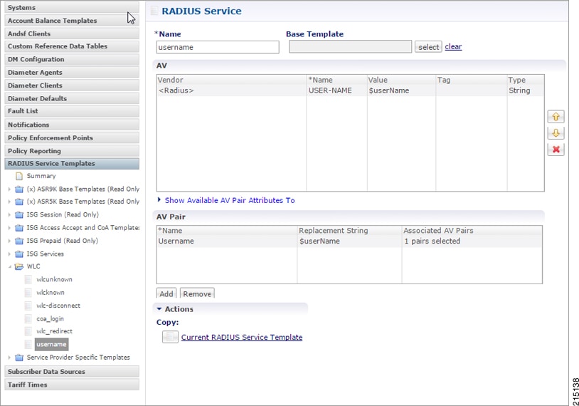 |
Domain Configuration
Configure a Domain “web-auth” for the subscribers and authorizations based on session username and User Password and set this domain as Default Domain.

Define locations based on Framed IP location type.

Set Advanced Rules For the MAC TAL.

Service Configuration: Use Case Template
Configure use Case Templates as “AccessAccept” and map the Service configuration Objects (Radius) “AccessAcceptConfiguration” from the Service Configurations pop-up dialog box.

Service Options
Based on above Use Case Templates, configure Service Options “wlc redirect” and “username”.


Service
Create a Service that will be assigned to the user account when the user connects for the first time and MAC TAL fails then assign an Unknown Service. For example, wlc-redirect.

Create a Service that will be assigned to the user account in the uSuM.

Control Center
Create subscribers in USuM database and add service type applicable to the subscriber. For more information on control center configuration, refer to Control Center Configuration.
 Feedback