Virtual Infrastructure Manager
UI Path: Virtual Management > Virtual Infrastructure Manager
 Note |
Ensure that you have enabled Network visualization of Virtual Machines feature for Cisco Nexus Dashboard Fabric Controller. |
The following table describes the fields that appear on Virtual Infrastructure Manager window:
|
Field |
Description |
|---|---|
|
Server |
Specifies the Server IP Address. |
|
Managed |
Specifies the status of the cluster either Managed or Unmanaged. |
|
Status |
Specifies the status of the added cluster. |
|
User |
Specifies the user created the cluster. |
|
LastUpdated Time |
Specifies the last updated time for the cluster. |
Note |
Click Refresh icon to refresh the Virtual Infrastructure Manager table. |
The following table describes the action items, in the Actions menu drop‐down list, that appear on Virtual Infrastructure Manager window:
|
Action Item |
Description |
||
|---|---|---|---|
|
Add Instance |
From the Actions drop-down list, choose Add Instance. For more instructions, see Adding an Instance.
|
||
|
Edit Instance |
Choose an instance to edit. From the Actions drop-down list, choose Edit Instance. Make the necessary changes and click Save. Click Cancel to discard the changes. | ||
|
Delete Instance(s) |
Choose one or more required instance to delete. From the Actions drop-down list, choose Delete Instance(s). Click Confirm to delete the instance. Click Cancel to discard the delete. |
||
|
Rediscover Instance(s) |
Choose one or more required instance to rediscover. From the Actions drop-down list, choose Rediscover Instance(s). A confirmation message appears. |
For more information:
Support for Cisco UCS B-Series Blade Servers
NDFC supports hosts running on UCS type B (chassis UCS) that are behind the Fabric interconnect. You must enable CDP of the vNIC on Cisco UCSM to use this feature.
Note |
By default, CDP is disabled on Cisco UCSM. |
Let us consider two VMMs, VMM‐A and VMM‐B, for reference. After the discovery of Cisco UCS UCS B-Series Blade Servers, the Topology displays the blue colored VMM‐A and VMM‐B are fabric interconnect nodes. A sample topology is as shown in the figure below.
To enable CDP on UCSM, you must create a new Network Control policy using the following steps:
-
On the USCM, choose LAN and expand the policies.
-
Right‐click on the Network Control Policies to create a new policy.
-
In the Name field, enter the policy name as EnableCDP.
-
Choose enabled option for CDP.
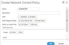
-
Click OK to create the policy.
To apply the new policy to the ESX NICs, perform the following steps:
-
If you are using updated vNIC templates, choose each vNIC template for your ESXi vNICs, and apply the EnableCDP policy from the Network Control Policy drop‐down list.
-
If you are not using any vNIC templates, use the updated Service Profile Template. Apply EnableCDP policy on each of the service profile template.
-
If you are using one‐off Service Profiles (i.e., if each server using its own service profile), then you must go to every Service Profile and enable EnableCDP policy on every vNIC.
For more information about Cisco UCSM, refer to Cisco UCSM Network Management Guide.
Configuring Routes IP Address
Before you add IP address to vCenter, you must configure same IP address on Cisco Nexus Dashboard.
To configure Routes on Cisco Nexus Dashboard, perform the following steps:
Procedure
|
Step 1 |
Choose Infrastructure > Cluster Configuration. |
|
Step 2 |
On General tab, in Routes card, click Edit icon. The Routes window appears. |
|
Step 3 |
To configure IP addresses, click Add Management Network Routes, enter required IP addresses, and click check icon. |
|
Step 4 |
Click Save. The route configuration is governed by following two scenarios:
|

 Feedback