EVPN Features

This chapter describes how to configure Layer 2 Ethernet VPN (EVPN) features on the router.

BUM Ingress Replication for EVPN E-LAN

Table 1. Feature History Table

Feature Name

Release Information

Feature Description

BUM Ingress Replication for EVPN E-LAN on 8212-48FH-M, 8711-32FH-M, 88-LC1-52Y8H-EM, and 88-LC1-12TH24FH-E

Release 24.3.1

The BUM ingress replication is now supported on these fixed systems and line cards:

  • 8212-48FH-M

  • 8711-32FH-M

  • 88-LC1-52Y8H-EM

  • 88-LC1-12TH24FH-E

BUM Ingress Replication for EVPN E-LAN on the 88-LC1-36EH Line Cards

Release 24.2.11

The BUM ingress replication is now supported on routers with the 88-LC1-36EH line cards.

BUM Ingress Replication for EVPN E-LAN

Release 7.11.1

You can optimize Broadcast, Unknown Unicast, and Multicast (BUM) traffic by ensuring that traffic that a device receives is replicated and forwarded to only those CE devices in an EVPN network, if and when they require it. This reduction in the unnecessary forwarding of BUM traffic prevents the flooding of BUM traffic to all devices on the EVPN network.

This feature is supported only on Q200-based line cards.

This feature is enabled by default.

EVPN BUM ingress replication handles the forwarding of BUM traffic within the network. When the router receives BUM traffic from a particular source, it replicates and forwards that traffic to all the relevant destinations. EVPN BUM ingress replication involves replicating the BUM traffic at the ingress (source) device and forwarding it to the appropriate egress (destination) devices.

The EVPN protocol uses MAC advertisement routes and control plane signaling to enable routers to selectively forward traffic to the intended recipient devices, preventing flooding the entire EVPN network.

Here's How it Works

  1. The ingress router learns MAC addresses associated with BUM traffic and also gathers information about multicast group membership for multicast traffic.

  2. Instead of flooding the BUM traffic across all ports in the EVPN, the ingress router replicates the traffic to the specific EVPN instances or Virtual Routing and Forwarding instances (VRFs) where it is needed. This ensures that BUM traffic is forwarded solely to the appropriate destinations.

  3. BGP signals and distributes MAC addresses and multicast information to other routers in the EVPN network. Ingress router replicates and transmits the BUM traffic to the designated locations.

Feature Highlights

  • EVPN BUM ingress replication optimizes resource allocation by forwarding BUM traffic to necessary EVPN instances or VRFs, minimizing traffic flooding, reducing congestion, and preserving bandwidth. Thereby, reducing the overhead and potential performance issues within a broadcast domain.

  • Effective BUM traffic management is vital for sustaining network scalability. EVPN BUM ingress replication guarantees directed BUM traffic distribution, supporting network scaling without overwhelming broadcast or multicast traffic.

  • EVPN BUM ingress replication improves network security by selectively duplicating BUM traffic to the designated recipients, thus limiting sensitive traffic exposure to unintended devices and unauthorized access risks.

  • In traditional Ethernet networks, broadcast storms occur when broadcast traffic is flooded throughout the network. EVPN BUM ingress replication reduces this risk by forwarding traffic only to the intended devices, preventing broadcast storms and network disruptions.
Split-Horizon Groups for EVPN E-LAN

Table 2. Feature History Table

Feature Name

Release Information

Feature Description

Split-Horizon Groups for EVPN E-LAN on 8212-48FH-M, 8711-32FH-M, 88-LC1-52Y8H-EM, and 88-LC1-12TH24FH-E

Release 24.3.1

The split-horizon groups for EVPN E-LAN is now supported on these fixed systems and line cards:

  • 8212-48FH-M

  • 8711-32FH-M

  • 88-LC1-52Y8H-EM

  • 88-LC1-12TH24FH-E

Split-Horizon Groups for EVPN E-LAN on the 88-LC1-36EH Line Cards

Release 24.2.11

The split-horizon groups for EVPN E-LAN is now supported on routers with the 88-LC1-36EH line cards.

Split-Horizon Groups for EVPN E-LAN

Release 7.11.1

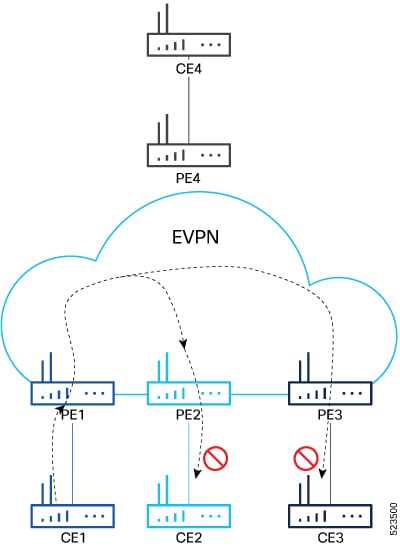
You can prevent unnecessary BUM traffic flooding and conserve bandwidth for single-homed EVPN scenarios by ensuring that the traffic isn’t sent back to the CE device from which it originated. Depending on the type of traffic you need to be forwarded or distributed, you can configure split-horizon group 0 (SG 0), SG 1, or SG 2.

This feature is supported only on Q200-based line cards.

The feature introduces the split-horizon group command.

Split horizon is a method for preventing loops in a network by placing forwarding or flooding restrictions between bridge ports based on group membership. The bridge domain aggregates attachment circuits (ACs) and pseudowires (PWs) in one of three groups called split-horizon groups. When applied to bridge domains, split-horizon refers to the flooding and forwarding behavior between members of a split-horizon group. Bridge domain traffic is either unicast or flooding.

Traffic flooding is performed for broadcast, multicast and unknown unicast destination address. Unicast traffic consists of frames sent to bridge-ports where the destination MAC address is known.

Flooding traffic consists of:

  • Unknown unicast destination MAC address frames

  • Frames sent to Ethernet multicast addresses, such as Spanning Tree Bridge Protocol Data Units ( BPDUs).

  • Ethernet broadcast frames (MAC address FF-FF-FF-FF-FF-FF)

Members within certain groups are forbidden to send traffic to each other. Members in different groups can send traffic to each other without restriction. These groups divide the network into segments with unique routes, improving traffic control and reducing packet congestion. This approach enhances network performance and reliability.

The following table describes how frames received on one member of a split-horizon group are treated and if the traffic is forwarded to the other members of the same split-horizon group. It describes the behavior of forwarding and flooding within and between groups as well as the assignment of Bridge Ports (BPs) to groups:

Table 3. Supported Split-Horizon Groups

Split-Horizon Group

Behavior

0

Default AC group. There is no forwarding and flooding restrictions. Forwards and floods traffic within the group and between all groups.

By default, all L2 ACs are added to this group by default. You cannot assign L2 ACs manually through the CLI.

1

Default VFI (core) PW group. Forwarding or flooding of traffic is restricted between bridge ports in this group. Forwarding or flooding of traffic to all other groups is allowed. All EVPN EVI virtual ports and VFI PWs are added to this group. You cannot assign VFI PWs manually through the CLI.

2

Optional AC group. Forwarding or flooding of traffic is restricted between bridge ports in this group. Forwarding or flooding traffic to all other groups is allowed. You can manually add ACs, and not VFI PWs using the CLI.

Configuration Example

Perform this task to configure split-horizon groups:


Router# configure
Router(config)# l2vpn
Router(config-l2vpn)# bridge group bg
Router(config-l2vpn-bg)# bridge-domain bd
Router(config-l2vpn-bg-bd-ac)# interface HundredGigE 0/0/0/24 <- (split-horizon group 0, default)
Router(config-l2vpn-bg-bd-ac)# interface HundredGigE 0/0/0/24.1
Router(config-l2vpn-bg-bd-evi)# split-horizon group <- (split-horizon group 2)
Router(config-l2vpn-bg-bd-evi)# neighbor 10.0.0.1 pw-id 1
Router(config-l2vpn-bg-bd-pw)# split-horizon group <- (split-horizon group 2)
Router(config-l2vpn-bg-bd-pw)# vfi vf
Router(config-l2vpn-bg-bd-vfi)# neighbor 172.16.0.1 pw-id 10001 <- (split-horizon group 1, default)
Router(config-l2vpn-bg-bd-vfi-pw)# exit
Router(config-l2vpn-bg-bd-vfi)# exit
Router(config-l2vpn-bg-bd)# evi 200
Router(config-l2vpn-bg-bd-evi)# commit

Running Configuration

This section shows the split-horizon groups running configuration.


l2vpn
  bridge group bg
   bridge-domain bd
    interface HundredGigE 0/0/0/24 <- (split-horizon group 0, default)
    interface HundredGigE 0/0/0/24.1
   !

     split-horizon group <- (split-horizon group 2)
    neighbor 10.0.0.1 pw-id 1
     split-horizon group <- (split-horizon group 2)
    vfi vf
      neighbor 172.16.0.1 pw-id 10001 <- (split-horizon group 1, default)
  !
   evi 200
!

Verification

The show l2vpn bridge-domain detail command output displays information about bridges, including whether each AC is in the AC split-horizon group or not.


Router# show l2vpn bridge-domain detail | i "AC:|Split Horizon|PW:|VFI"
MAC withdraw for Access PW: enabled
Split Horizon Group: none
P2MP PW: disabled
ACs: 2 (2 up), VFIs: 1, PWs: 2 (0 up), PBBs: 0 (0 up), VNIs: 0 (0 up)
AC: HundredGigE 0/0/0/24, state is up
Split Horizon Group: none
AC: HundredGigE 0/0/0/24.1, state is up
Split Horizon Group: enabled 
PW: neighbor 10.0.0.1, pw-id 1, state is up ( established )
Split Horizon Group: enabled
List of VFIs:
VFI vf (up)
PW: neighbor 172.16.0.1, pw-id 10001, state is up ( established )
Split Horizon Group: none

VRF Leaking for EVPN E-LAN

Table 4. Feature History Table

Feature Name

Release Information

Feature Description

VRF Leaking for EVPN E-LAN on 8212-48FH-M, 8711-32FH-M, 88-LC1-52Y8H-EM, and 88-LC1-12TH24FH-E

Release 24.3.1

The VRF leaking for EVPN E-LAN is now supported on these fixed systems and line cards:

  • 8212-48FH-M

  • 8711-32FH-M

  • 88-LC1-52Y8H-EM

  • 88-LC1-12TH24FH-E

VRF Leaking for EVPN E-LAN on the 88-LC1-36EH Line Cards

Release 24.2.11

The VRF leaking for EVPN E-LAN is now supported on routers with the 88-LC1-36EH line cards.

VRF Leaking for EVPN E-LAN

Release 7.11.1

We now allow for seamless intercommunication between different VRF instances in an EVPN domain, thus enabling controlled inter-VRF communication and resource-sharing, which is helpful in multi-tenancy environments, data center deployments, and hybrid cloud scenarios.

This feature is supported only on Q200-based line cards.

For virtualization, multiple virtual networks are created using VRFs to provide logical separation of network resources, enabling different network domains to have their own isolated virtual networks. Each VRF operates in isolation with its own routing table, forwarding behavior, and network policies. Devices within a VRF can communicate with each other but are isolated from devices in other VRFs.

However, these isolated domains often need to communicate with each other, such as providing services, sharing resources, centralized management, and monitoring.

In EVPN network, VRF leaking facilitates the controlled exchange of information between different VRF instances within an EVPN framework. It acts as a mechanism to share routes selectively and enable communication between VRFs at Layer 2 when a customer edge device is connected to a single provider edge router. By using VRF leaking, we now provide both isolation and segmentation among VRFs while still allowing inter-VRF communication through EVPN route type 2 (MAC+IP) import. This mechanism enables controlled communication between VRFs, permitting specific routes or traffic to traverse VRF boundaries while preserving the isolation of unrelated routes and traffic.

VRF leaking or stitching is a technique used in multi-VRF environments to enable communication between two or more VRFs at Layer 2. With VRF Leaking, you can interconnect VRFs at Layer 2, which allows traffic to flow between them using Layer 2 gateways, which act as bridge devices to forward traffic between VRFs.

You can connect different VRFs using a Layer 2 gateway or bridge to allow traffic between the VRFs in an EVPN network. You can define traffic policies to allow traffic to pass between the VRFs, which includes filtering based on EVPN EVI, and/or MAC addresses. After the Layer 2 gateway and traffic policies are configured, communication between the VRFs is established at Layer 2. Layer 2 frames can now be forwarded between the VRFs while maintaining the VRF isolation for Layer 3 traffic.

Configure VRF Leaking

Perform these tasks to configure VRF route leak between global route table and VRF route table.

  1. Configure BGP where the router performs the route leak.

  2. Configure the route policies, these policies help you filter which prefixes are permitted to be leaked. In this example, the route-policy GLOBAL-2-VRF and route-policy VRF-2-GLOBAL are used.

  3. Configure the VRF and apply the route-policy.

Configuration Example


/* Configure BGP */
Router(config)# router bgp 100
Router(config-bgp)# bgp router-id 10.10.10.10
Router(config-bgp)# address-family ipv4 unicast
Router(config-bgp-af)# network 172.16.20.0/24
Router(config-bgp-af)# exit
Router(config-bgp)# address-family vpnv4 unicast
Router(config-bgp-af)# exit
Router(config-bgp)# vrf ORANGE
Router(config-bgp-vrf)# rd 100:100
Router(config-bgp-vrf)# address-family ipv4 unicast
Router(config-bgp-vrf-af)# network 192.168.10.0/24
Router(config-bgp-vrf-af)# commit

/* Configure route policies */
Router(config)# route-policy GLOBAL-2-VRF
Router(config-rpl)# if destination in (172.16.20.0/24) then
Router(config-rpl-if)# pass
Router(config-rpl-if)# endif
Router(config-rpl)# end-policy
Router(config)# route-policy VRF-2-GLOBAL
Router(config-rpl)# if destination in (192.168.10.0/24 le 32) then
Router(config-rpl-if)# pass
Router(config-rpl-if)# endif
Router(config-rpl)# end-policy

/* Configure VRF and apply route-policy */
Router(config)# vrf ORANGE
Router(config-vrf)# address-family ipv4 unicast
Router(config-vrf-af)# import from default-vrf route-policy GLOBAL-2-VRF
Router(config-vrf-af)# import route-target
Router(config-vrf-import-rt)# 100:100
Router(config-vrf-import-rt)# exit
Router(config-vrf-af)# export to default-vrf route-policy VRF-2-GLOBAL
Router(config-vrf-af)# export route-target
Router(config-vrf-export-rt)# 100:100
Router(config-vrf-export-rt)# commit

Running Configuration

This section shows the VRF leaking running configuration.


router bgp 100
 bgp router-id 10.10.10.10
 address-family ipv4 unicast
  network 172.16.20.0/24
 !
 address-family vpnv4 unicast
 !
 vrf ORANGE
  rd 100:100
  address-family ipv4 unicast
   network 192.168.10.0/24
  !
 !
!
route-policy GLOBAL-2-VRF
  if destination in (172.16.20.0/24) then
    pass
  endif
end-policy
!
route-policy VRF-2-GLOBAL
  if destination in (192.168.10.0/24 le 32) then
    pass
  endif
end-policy
!
vrf ORANGE
 address-family ipv4 unicast
  import from default-vrf route-policy GLOBAL-2-VRF
  import route-target
   100:100
  !
  export to default-vrf route-policy VRF-2-GLOBAL
  export route-target
   100:100
  !
 !
!

Verification

Verify the prefixes appear in the RIB and BGP tables.

Router# show route
Codes: C - connected, S - static, R - RIP, B - BGP, (>) - Diversion path
       D - EIGRP, EX - EIGRP external, O - OSPF, IA - OSPF inter area
       N1 - OSPF NSSA external type 1, N2 - OSPF NSSA external type 2
       E1 - OSPF external type 1, E2 - OSPF external type 2, E - EGP
       i - ISIS, L1 - IS-IS level-1, L2 - IS-IS level-2
       ia - IS-IS inter area, su - IS-IS summary null, * - candidate default
       U - per-user static route, o - ODR, L - local, G  - DAGR, l - LISP
       A - access/subscriber, a - Application route
       M - mobile route, r - RPL, t - Traffic Engineering, (!) - FRR Backup path

Gateway of last resort is not set

C    10.88.174.0/24 is directly connected, 1d20h, MgmtEth0/RSP0/CPU0/0
L    10.88.174.223/32 is directly connected, 1d20h, MgmtEth0/RSP0/CPU0/0
L    10.10.10.10/32 is directly connected, 04:33:44, Loopback100
C    172.16.20.0/24 is directly connected, 07:03:18, HundredGigE0/0/0/24
L    172.16.20.1/32 is directly connected, 07:03:18, HundredGigE0/0/0/24
B    192.168.10.0/24 is directly connected, 03:02:21, HundredGigE0/0/0/0 (nexthop in vrf ORANGE)

Router# show ip bgp
BGP router identifier 10.10.10.10, local AS number 100
BGP generic scan interval 60 secs
Non-stop routing is enabled
BGP table state: Active
Table ID: 0xe0000000   RD version: 5
BGP main routing table version 5
BGP NSR Initial initsync version 3 (Reached)
BGP NSR/ISSU Sync-Group versions 0/0
BGP scan interval 60 secs

Status codes: s suppressed, d damped, h history, * valid, > best
              i - internal, r RIB-failure, S stale, N Nexthop-discard
Origin codes: i - IGP, e - EGP, ? - incomplete
   Network            Next Hop            Metric LocPrf Weight Path
*> 172.16.20.0/24     0.0.0.0                  0         32768 i
*> 192.168.10.0/24    0.0.0.0                  0         32768 i

Processed 2 prefixes, 2 paths

The following show output displays the information for the VRF ORANGE:

Router# show route vrf ORANGE 
Codes: C - connected, S - static, R - RIP, B - BGP, (>) - Diversion path
       D - EIGRP, EX - EIGRP external, O - OSPF, IA - OSPF inter area
       N1 - OSPF NSSA external type 1, N2 - OSPF NSSA external type 2
       E1 - OSPF external type 1, E2 - OSPF external type 2, E - EGP
       i - ISIS, L1 - IS-IS level-1, L2 - IS-IS level-2
       ia - IS-IS inter area, su - IS-IS summary null, * - candidate default
       U - per-user static route, o - ODR, L - local, G  - DAGR, l - LISP
       A - access/subscriber, a - Application route
       M - mobile route, r - RPL, t - Traffic Engineering, (!) - FRR Backup path

Gateway of last resort is not set

B    172.16.20.0/24 is directly connected, 01:43:49, HundredGigE0/0/0/24 (nexthop in vrf default)
   C    192.168.10.0/24 is directly connected, 07:06:38, HundredGigE0/0/0/24
   L    192.168.10.2/32 is directly connected, 07:06:38, HundredGigE0/0/0/0


Router# show bgp vrf ORANGE
BGP VRF ORANGE, state: Active
BGP Route Distinguisher: 100:100
VRF ID: 0x60000003
BGP router identifier 10.10.10.10, local AS number 100
Non-stop routing is enabled
BGP table state: Active
Table ID: 0xe0000012   RD version: 9
BGP main routing table version 9
BGP NSR Initial initsync version 4 (Reached)
BGP NSR/ISSU Sync-Group versions 0/0

Status codes: s suppressed, d damped, h history, * valid, > best
              i - internal, r RIB-failure, S stale, N Nexthop-discard
Origin codes: i - IGP, e - EGP, ? - incomplete
   Network            Next Hop            Metric LocPrf Weight Path
Route Distinguisher: 100:100 (default for vrf ORANGE)
*> 172.16.20.0/24     0.0.0.0                  0         32768 i
*> 192.168.10.0/24    0.0.0.0                  0         32768 i

Processed 2 prefixes, 2 paths

Core Isolation by Interface Tracking for EVPN E-LAN

Table 5. Feature History Table

Feature Name

Release Information

Feature Description

Core Isolation by Interface Tracking on 8212-48FH-M, 8711-32FH-M, 88-LC1-52Y8H-EM, and 88-LC1-12TH24FH-E

Release 24.3.1

The core isolation by interface tracking is now supported on these fixed systems and line cards:

  • 8212-48FH-M

  • 8711-32FH-M

  • 88-LC1-52Y8H-EM

  • 88-LC1-12TH24FH-E

Core Isolation by Interface Tracking on the 88-LC1-36EH Line Cards

Release 24.2.11

The core isolation by interface tracking is now supported on routers with the 88-LC1-36EH line cards.

Core Isolation by Interface Tracking for EVPN E-LAN

Release 7.11.1

You can now monitor the connectivity of the customer-facing interface on the PE router using object tracking (OT). If the interface fails or becomes unavailable, the router isolates the customer site from the rest of the EVPN network. Isolating the core from the network prevents the customer site from advertising its routes to other sites on the EVPN single-home network, ensuring that traffic isn't sent to the failed PE router.

Object tracking involves continuous monitoring of network interfaces, including links or ports on routers. By actively observing the status of these interfaces, administrators can dynamically adjust the network configuration based on their availability and health.

This feature is supported only on Q200-based line cards.

Use Object Tracking commands to track and monitor the connected interfaces.

You can effectively isolate the core provider edge if there are any issues or failures in the connected interfaces, ensuring that the rest of the network remains unaffected and operational.

To isolate the core provider edge device, you can configure the device to track the interfaces connecting to the core provider edge. To do this, you can assign a tracking object to those interfaces. The tracking object monitors the state of the interfaces, such as link up or link down.

Object Tracking

The object that receives the action may not have any relationship with the tracked objects, and the action is based on changes in the properties of the tracked object. A specific network element, such as a static route or interface status, is considered an object tracked and monitored by the device. Each tracked object is identified by a unique name specified by the track command in configuration mode. When the state of the tracked object changes, the tracking process receives the notification. The tracked objects can have an up or down state. A list can track multiple objects using a flexible method that combines objects with Boolean logic. This functionality includes

Object tracking (OT) is a mechanism for tracking an object to take any action on another object as configured by the user. The object that receives the action may not have any relationship with the tracked objects, and the action is based on changes in the properties of the tracked object. A specific network element, such as a static route or interface status, is considered an object tracked and monitored by the device.

Each tracked object is identified by a unique name specified by the track command in configuration mode.

When the state of the tracked object changes, the tracking process receives the notification. The tracked objects can have an up or down state. A list can track multiple objects using a flexible method that combines objects with Boolean logic. This functionality includes:

  • Boolean AND function—When a tracked list has been assigned a Boolean AND function, each object defined within a subset must be in an up state, so that the tracked object can also be in the up state.

  • Boolean OR function—When the tracked list has been assigned a Boolean OR function, it means that at least one object defined within a subset must also be in an up state, so that the tracked object can also be in the up state.

Here are some of the object tracking benefits:

  • Provides real-time monitoring of network elements and tracks the reachability and availability of important objects in the network.

  • You can automate network management tasks and implement dynamic failover or load balancing mechanisms based on the state changes of tracked objects.

  • You can improve network availability by quickly detecting and responding to changes in the status of tracked objects. This enables proactive measures to be taken to minimize network downtime.

  • You can define policies and actions to be triggered when the state of a tracked object changes. This allows for flexible network management and the ability to implement specific actions based on network conditions.

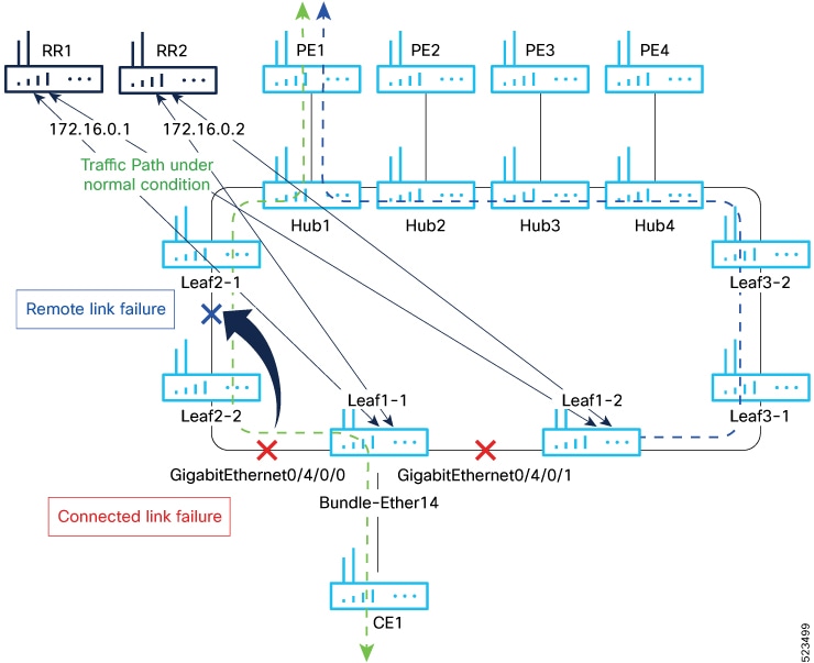
Figure 1. Core Isolation by Interface Tracking

Consider a traffic flow from CE1 to PE1. The CE1 sends the traffic from Leaf1-1. When Leaf1-1 loses the connectivity to both the local links and remote link, BGP sessions to both route reflectors (RRs) are down; the Leaf1-1 brings down the Bundle-Ether14 connected to CE1.

You can track the connected interfaces to identify the link failures. However, if there is a remote link failure, tracking connected interfaces does not identify the remote link failures. You must track BGP sessions to identify the remote link failure.

Configure EVPN Core Isolation

Perform the following tasks to configure EVPN core isolation:

  1. Configure BGP

  2. Track the Line Protocol State of an interface

  3. Track neighbor address-family state

  4. Track objects for both interfaces and neighbors


Note


  • An object must exist before it can be added to a tracked list.

    A tracked list contains one or more objects. The Boolean expression enables tracking objects using either AND or OR operators. For example, when tracking two interfaces, using the AND operator, up means that both interfaces are up, and down means that either interface is down.

  • The NOT operator is specified for one or more objects and negates the state of the object.

  • After configuring the tracked object, you must associate the neighbor or interface whose state must be tracked.


Configuration Example

In this example, Leaf1-1 brings the down the AC connected to CE1 when:

Both local interfaces GigabitEthernet0/4/0/0 and GigabitEthernet0/4/0/1of Leaf1-1 are down.

OR

Leaf1-1 BGP sessions to both RRs are down.

Perform the following tasks on Leaf1-1:


/* Configure BGP */
Router# configure
Router(config)# router bgp 100
Router(config-bgp)# address-family l2vpn evpn
Router(config-bgp-af)# exit
Router(config-bgp)# neighbor 172.16.0.1
Router(config-bgp-nbr)# remote-as 100
Router(config-bgp-nbr)# address-family l2vpn evpn
Router(config-bgp-nbr-af)# neighbor 172.16.0.1
Router(config-bgp-nbr)# remote-as 100
Router(config-bgp-nbr)# address-family l2vpn evpn
Router(config-bgp-nbr-af)# commit

/* Track the Line Protocol State of an Interface */
Router# configure
Router(config)# track interface-1
Router(config-track)# type line-protocol state
Router(config-track-line-prot)# interface HundredGigE0/0/0/24
Router(config-track-line-prot)#exit
Router(config-track)#exit
Router(config)# track interface-2
Router(config-track)# type line-protocol state
Router(config-track-line-prot)# interface HundredGigE0/0/0/25
Router(config-track-line-prot)#exit
Router(config-track)#exit
Router(config)# track interface-group-1 
Router(config-track)# type list boolean or
Router(config-track-list-boolean)# object interface-1
Router(config-track-list-boolean)# object interface-2
Router(config-track-list-boolean)# commit

/* Track neighbor address-family state */
Router# configure
Router(config)# track neighbor-A
Router(config-track)# type bgp neighbor address-family state
Router(config-track-bgp-nbr-af)# address-family l2vpn evpn
Router(config-track-bgp-neighbor)# neighbor 172.16.0.1
Router(config-track-bgp-neighbor)# exit
Router(config-track-bgp-nbr-af)# exit
Router(config-track)# exit
Router(config)# track neighbor-B
Router(config-track)# type bgp neighbor address-family state
Router(config-track-bgp-nbr-af)# address-family l2vpn evpn
Router(config-track-bgp-neighbor)# neighbor 172.16.0.2
Router(config-track-bgp-neighbor)# exit
Router(config-track-bgp-nbr-af)# exit
Router(config-track)# exit
Router(config)# track neighbor-group-1
Router(config-track)# type list boolean or
Router(config-track-list-boolean)# object neighbor-A
Router(config-track-list-boolean)# object neighbor-B
Router(config-track-list-boolean)# commit

/* Track objects for both interfaces and neighbors */
Router# configure
Router(config)# track core-group-1
Router(config-track)# type list boolean and
Router(config-track-list-boolean)# object neighbor-group-1
Router(config-track-list-boolean)# object interface-group-1
Router(config-track-list-boolean)# action
Router(config-track-action)# track-down error-disable interface Bundle-Ether14 auto-recover
Router(config-track-action)# commit

Running Configuration

This section shows the EVPN core isolation running configuration.


router bgp 100
 address-family l2vpn evpn
 !
 neighbor 172.16.0.1
  remote-as 100
  address-family l2vpn evpn
  !
 !
 neighbor 172.16.0.2
  remote-as 100
  address-family l2vpn evpn
  !
 !
!

track interface-1
 type line-protocol state
  interface HundredGigE0/0/0/24
 !
!
track interface-2
 type line-protocol state
  interface HundredGigE0/0/0/25
 !
!
track interface-group-1
 type list boolean or
  object interface-1
  object interface-2
 !
!

track neighbor-A
 type bgp neighbor address-family state
  address-family l2vpn evpn
   neighbor 172.16.0.1
  !
 !
!
track neighbor-B
 type bgp neighbor address-family state
  address-family l2vpn evpn
   neighbor 172.16.0.1
  !
 !
!    

track neighbor-group-1
 type list boolean or
  object neighbor-A
  object neighbor-B
  !
 !
!
track core-group-1
 type list boolean and
  object neighbor-group-1
  object interface-group-1
 !
 action
  track-down error-disable interface Bundle-Ether14 auto-recover
  !
 !

Verification

Verify and track the status of interfaces and core group. The following show output examples display the status of interfaces and tracks as UP.


Router# show track

Track neighbor-A 
        BGP Neighbor AF L2VPN EVPN NBR 172.16.0.1 vrf default
        Reachability is UP 
                Neighbor Address Reachablity is Up
                BGP Neighbor Address-family state is Up
        4 changes, last change UTC Tue May 26 2020 20:14:33.171

Track neighbor-B 
        BGP Neighbor AF L2VPN EVPN NBR 172.16.0.2 vrf default
        Reachability is UP 
                Neighbor Address Reachablity is Up
                BGP Neighbor Address-family state is Up
        4 changes, last change UTC Tue May 26 2020 20:14:27.527

Track core-group-1 
        List boolean and is UP 
        2 changes, last change 20:14:27 UTC Tue May 26 2020
                object interface-group-1 UP
                object neighbor-group-1 UP

Track interface-1 
        Interface HundredGigE0/0/0/24 line-protocol
        Line protocol is UP 
        2 changes, last change 20:13:32 UTC Tue May 26 2020

Track interface-2 
        Interface HundredGigE0/0/0/25 line-protocol
        Line protocol is UP 
        2 changes, last change 20:13:28 UTC Tue May 26 2020

Track interface-group-1
        List boolean or is UP 
        2 changes, last change 20:13:28 UTC Tue May 26 2020
                object interface-2 UP
                object interface-1 UP

Track neighbor-group-1
        List boolean or is UP 
        2 changes, last change 20:14:27 UTC Tue May 26 2020
                object neighbor-A UP
                object neighbor-B UP


Router# show track brief
Track                            Object                                    Parameter         Value                
--------------------------------------------------------------------------------------------------------------
neighbor-A                       bgp nbr L2VPN EVPN 172.16.0.1 vrf default reachability     Up            
neighbor-B                       bgp nbr L2VPN EVPN 172.16.0.1 vrf default reachability     Up            
core-group-1                     list                                      boolean and      Up   
interface-1                      interface HundredGigE0/0/0/24             line protocol    Up   
interface-2                      interface HundredGigE0/0/0/25             line protocol    Up   
interface-group-1                list                                      boolean or       Up   
neighbor-group-1                 list                                      boolean or       Up   
---------------------------------------------------------------------------------------------------------------

Router# show bgp track 
Wed May 27 05:05:51.285 UTC

VRF                    Address-family       Neighbor         Status     Flags

default                L2VPN EVPN           172.16.0.1     UP         0x01
default                L2VPN EVPN           172.16.0.2     UP         0x01

Processed 2 entries

The following output shows that when interfaces HundredGigE0/0/0/24 and HundredGigE0/0/0/25 go down, error-disable is triggered on the Bundle-Ether14 interface.


Router# show track brief
Track                            Object                                    Parameter      Value                
--------------------------------------------------------------------------------------------------------------
neighbor-A                       bgp nbr L2VPN EVPN 172.16.0.1 vrf defau reachability     DOWN            
neighbor-B                       bgp nbr L2VPN EVPN 172.16.0.1 vrf defau reachability     DOWN            
core-group-1                     list                                      boolean and    DOWN   
interface-1                      interface HundredGigE0/0/0/24             line protocol  DOWN   
interface-2                      interface HundredGigE0/0/0/25             line protocol  DOWN   
interface-group-1                list                                      boolean or     DOWN   
neighbor-group-1                 list                                      boolean or     DOWN   
---------------------------------------------------------------------------------------------------------------

Router# show bgp track 

VRF                    Address-family       Neighbor         Status     Flags
default                L2VPN EVPN           172.16.0.1       DOWN       0x01
default                L2VPN EVPN           172.16.0.2       DOWN       0x01

Processed 2 entries
---------------------------------------------------------------------------------------------------------------

Router# show interfaces bundle-ether14
Bundle-Ether14 is error disabled, line protocol is administratively down 
  Interface state transitions: 2
  Hardware is Aggregated Ethernet interface(s), address is 0024.f715.36c0
  Internet address is Unknown
  MTU 1514 bytes, BW 0 Kbit
     reliability 255/255, txload Unknown, rxload Unknown
  Encapsulation ARPA,
  Full-duplex, 0Kb/s
  loopback not set,
  Last link flapped 00:01:04
    No. of members in this bundle: 1
      TenGigE0/0/0/6/7             Full-duplex  10000Mb/s    Configured      
  Last input 00:01:04, output 00:01:04
  Last clearing of "show interface" counters 04:44:35
  5 minute input rate 0 bits/sec, 0 packets/sec
  5 minute output rate 0 bits/sec, 0 packets/sec
     263008898 packets input, 212215917663 bytes, 0 total input drops
     0 drops for unrecognized upper-level protocol
     Received 130838604 broadcast packets, 130840312 multicast packets
              0 runts, 0 giants, 0 throttles, 0 parity
     0 input errors, 0 CRC, 0 frame, 0 overrun, 0 ignored, 0 abort
     787685280 packets output, 637258623124 bytes, 0 total output drops
     Output 393146795 broadcast packets, 393148545 multicast packets
     0 output errors, 0 underruns, 0 applique, 0 resets
     0 output buffer failures, 0 output buffers swapped out
     0 carrier transitions

EVPN Core Isolation through Peer Failure Detection

Table 6. Feature History Table

Feature Name

Release Information

Feature Description

EVPN Core Isolation through Peer Failure Detection on 8212-48FH-M, 8711-32FH-M, 88-LC1-52Y8H-EM, and 88-LC1-12TH24FH-E

Release 24.3.1

EVPN Core Isolation through Peer Failure Detection is now supported on these fixed systems and line cards:

  • 8212-48FH-M

  • 8711-32FH-M

  • 88-LC1-52Y8H-EM

  • 88-LC1-12TH24FH-E

EVPN Core Isolation through Peer Failure Detection on the 88-LC1-36EH Line Cards

Release 24.2.11

EVPN Core Isolation through Peer Failure Detection is now supported on the 88-LC1-36EH line cards.

EVPN Core Isolation through Peer Failure Detection

Release 7.11.1

You can now isolate the provider edge (PE) device from the network when there is a core link failure, preventing traffic disruptions and data leakage that could result from a compromised or malfunctioning peer. Upon detecting a link failure, the affected PE device is isolated from the core network, and the EVPN brings down the PE's Ethernet Segment (ES), which is associated with the access interface attached to the customer edge (CE) device.

This feature is supported only on Q200-based line cards.

The feature introduces the core-isolation-group command.

You can now detect a core link failure and isolate the affected PE device from the network, ensuring the continued operation and security of the EVPN network. EVPN core isolation is highly beneficial, especially in extensive deployments such as data centers. This method guarantees the stability, security, and efficiency of the EVPN network by segregating various segments or sites within the core network.

When a core link failure is detected in the provider edge (PE) device, EVPN brings down the PE's Ethernet Segment (ES), which is associated with the access interface attached to the customer edge (CE) device.

Consider a topology where CE is connected to PE1. PE1 and PE2 are running EVPN over the MPLS core network. The core interfaces can be Gigabit Ethernet or bundle interface, while the access interface can only be a bundle interface.

Figure 2. EVPN Core Isolation Protection

When the core links of PE1 go down, the EVPN detects the link failure and isolates the PE1 node from the core network by bringing down the access network. This prevents CE from sending any traffic to PE1. Since the BGP session also goes down, the BGP invalidates all the routes that the failed PE advertised.

When all the core interfaces and BGP sessions come up, PE1 advertises Ethernet A-D Ethernet Segment (ES-EAD) routes again, triggers the service carving, and becomes part of the core network.

Configure EVPN Core Isolation

Configure core interfaces under the EVPN group and associate that group to the Ethernet Segment which is an attachment circuit (AC) attached to the CE. When all the core interfaces go down, EVPN brings down the associated access interfaces which prevents the CE device from using those links within their bundles. All interfaces that are part of a group go down, EVPN brings down the bundle and withdraws the ES-EAD route.

Restrictions

  • A maximum of 24 groups can be created under the EVPN.

  • A maximum of 12 core interfaces can be added under the group.

  • The core interfaces can be reused among the groups. The core interface can be a bundle interface.

  • EVPN group must only contain core interfaces, do not add access interfaces under the EVPN group.

  • The access interface can only be a bundle interface.

Configuration Example

In this example, configure core interfaces under the EVPN group and associate that group to the attachment circuit (AC) connected to the EVPN single-homing CE device.


Router# configure
Router(config)# evpn
Router(config-evpn)# group 42001
Router(config-evpn-group)# core interface HundredGigE 0/0/0/24
Router(config-evpn-group)# core interface HundredGigE 0/0/0/25
Router(config-evpn-group)#exit
!
Router(config-evpn)# group 43001
Router(config-evpn-group)# core interface HundredGigE 0/0/0/26
Router(config-evpn-group)# core interface HundredGigE 0/0/0/27
Router(config-evpn-group)#exit
!
Router# configure
Router(config)# evpn
Router(config-evpn)# interface bundle-Ether 42001
Router(config-evpn-ac)# core-isolation-group 42001
Router(config-evpn-ac)# exit
!
Router(config-evpn)# interface bundle-Ether 43001
Router(config-evpn-ac)# core-isolation-group 43001
Router(config-evpn-ac)# commit

Running Configuration


configure
 evpn
  group 42001
   core interface HundredGigE 0/0/0/24
   core interface HundredGigE 0/0/0/25
   !
  group 43001
   core interface HundredGigE 0/0/0/26
   core interface HundredGigE 0/0/0/27
   !
 !
configure
 evpn
  interface bundle-Ether 42001
   core-isolation-group 42001
   !
  interface bundle-Ether 43001
   core-isolation-group 43001
   !
  !

Verification

The show evpn group command displays the complete list of EVPN groups, their associated core interfaces and access interfaces. The status, up or down, of each interface is displayed. For the access interface to be up, at least one of the core interfaces must be up.

The following output shows that the core is isolated because the core interfaces are down, bringing down the access interfaces connected to this core.


Router# show evpn group 
EVPN Group: 42001
  State: Isolated
  Core Interfaces:
     HundredGigE 0/0/0/24: down
     HundredGigE 0/0/0/25: down
     
  Access Interfaces:
     Bundle-Ether42001: down

The following output shows that the core is in the Ready state because both the core and access interfaces are UP.


Router# show evpn group
EVPN Group: 43001
  State: Ready
  Core Interfaces:           
     HundredGigE 0/0/0/26: up
     HundredGigE 0/0/0/27: up
     
  Access Interfaces:
     Bundle-Ether43001: up

MAC Mobility for EVPN E-LAN

Table 7. Feature History Table

Feature Name

Release Information

Feature Description

MAC Mobility for EVPN E-LAN on 8212-48FH-M, 8711-32FH-M, 88-LC1-52Y8H-EM, and 88-LC1-12TH24FH-E

Release 24.3.1

The MAC mobility for EVPN E-LAN is now supported on these fixed systems and line cards:

  • 8212-48FH-M

  • 8711-32FH-M

  • 88-LC1-52Y8H-EM

  • 88-LC1-12TH24FH-E

MAC Mobility for EVPN E-LAN on the 88-LC1-36EH Line Cards

Release 24.2.11

The MAC mobility for EVPN E-LAN is now supported on routers with the 88-LC1-36EH line cards.

MAC Mobility for EVPN E-LAN

Release 7.11.1

You can now seamlessly move MAC addresses between various network devices or locations while preserving their connectivity and associated network services. This ensures uninterrupted communication for devices or virtual machines frequently changing their physical or virtual location within the network. The L2 gateway dynamically updates its forwarding table when a MAC address moves from one device to another within the EVPN E-LAN network, guaranteeing that packets destined for that MAC address are correctly forwarded to its new location.

This feature is supported only on Q200-based line cards.

MAC Mobility provides the flexibility to move devices or virtual machines to different physical hosts or locations within the network, which enables efficient resource utilization by enabling dynamic distribution of traffic and optimized routing decisions based on the location of MAC addresses. This feature is valuable in scenarios such as data centers, where virtual machines or containers must be able to move across physical hosts without disrupting their network connectivity.

Feature Highlights

  • Facilitates seamless movement of MAC addresses among different devices or network locations, maintaining uninterrupted connectivity. This agility allows devices or virtual machines to be flexible and mobile, accommodating dynamic workloads and efficient resource allocation.

  • Manages a substantial volume of mobile devices or virtual machines, permitting seamless movement across different network segments without causing disruptions or requiring manual reconfiguration.

  • Ensures that packets are appropriately forwarded to the updated MAC address locations, optimizing routing decisions, curbing unnecessary traffic, and enhancing overall network performance.

  • Eliminates the need for manual configuration changes when devices or virtual machines move within the network. This simplifies network management and reduces the likelihood of human errors or misconfigurations.

MAC mobility supports:

Detect and Block Duplicate MAC Addresses

Table 8. Feature History Table

Feature Name

Release Information

Feature Description

Detect and Block Duplicate MAC Addresses on 8212-48FH-M, 8711-32FH-M, 88-LC1-52Y8H-EM, and 88-LC1-12TH24FH-E

Release 24.3.1

The Detect and Block Duplicate MAC Addresses feature is now supported on these fixed systems and line cards:

  • 8212-48FH-M

  • 8711-32FH-M

  • 88-LC1-52Y8H-EM

  • 88-LC1-12TH24FH-E

Detect and Block Duplicate MAC Addresses on the 88-LC1-36EH Line Cards

Release 24.2.11

The Detect and Block Duplicate MAC Addresses feature is now supported on the 88-LC1-36EH line cards.

Detect and Block Duplicate MAC Addresses

Release 7.11.1

You can now effectively mitigate traffic disruptions, packet loss, and potential network outages in your network operations by detecting and freezing duplicate MAC addresses and blocking all associated routes.

This feature is supported only on Q200-based line cards.

The feature introduces the host mac-address duplicate-detection command.

The duplicate MAC address detection feature automatically checks any host with a duplicate MAC address and blocks all routes that have a duplicate MAC address, as hosts with duplicate MAC addresses can cause unnecessary churn in a network and result in traffic loss for either or both hosts sharing the same MAC address.

Multiple devices sharing identical MAC addresses can cause MAC address flapping, which intermittently results in different devices claiming the same MAC address and causing network devices to update their forwarding tables constantly. Duplicate MAC addresses may lead to excessive network traffic, increased CPU utilization on network devices, and overall instability.

Based on the predefined parameters, the router identifies and freezes a duplicate MAC address. However, you can use a configuration option to prevent the MAC address from being permanently frozen, offering flexibility in managing network configurations.

The router keeps track of MAC addresses as they move from one host to another, handling the mobility of EVPN hosts. The router learns and relearns MAC routes from both hosts if two hosts have the same MAC address. Each time it learns the MAC route from one host, it counts as one move, as the newly learned route supersedes the previous route learned from the other host. This process continues back and forth until the router marks the MAC address as a duplicate based on the configured parameters. Use the host mac-address duplicate-detection command to configure the router when to mark a MAC address as duplicate and whether to freeze or unfreeze it as it moves between different hosts using the following configurable parameters.

  • move-count: The number of times a MAC address has changed its location within a specified period between different hosts to be considered a duplicate. The period is specified in the move-interval parameter.

  • move-interval: The duration within which a MAC address moves a certain number of times between different hosts to be considered as duplicate and frozen temporarily. This number is specified in the move-count parameter.

  • freeze-time: The length of time a MAC address is locked after it has been detected as a duplicate. After this period, the MAC address is unlocked and it is allowed to learn again.

  • retry-count: The number of times a MAC address is unlocked after it has been detected as a duplicate before it is frozen permanently.

A syslog notifies the user that the particular MAC address is frozen. While a MAC address is frozen, any new MAC routes or updates to existing MAC routes with the frozen MAC address are ignored. After the freeze-time has elapsed, the corresponding MAC routes are unfrozen and the value of the move-count is reset to zero. For any unfrozen local MAC routes, an ARP probe and flush are initiated while the remote MAC routes are put in the probe mode. This restarts the duplicate detection process.

The router also maintains the information about the number of times a particular MAC address has been frozen and unfrozen. If a MAC address is marked as duplicate after it is unfrozen retry-count times, it is frozen permanently. However, you can unfreeze permanently frozen hosts using any of the following recommended procedures to clear frozen hosts:

  • Shut down the host which is causing duplicate traffic.

  • Use the clear l2route evpn frozen-mac frozen-flag command to clear the frozen hosts.

How to Prevent MAC Address Freezing

You can unfreeze the permanently frozen MAC addresses with a configurable option to enable a MAC address to undergo infinite duplicate detection and recovery cycles without being frozen permanently. The MAC address is permanently frozen when duplicate detection and recovery events occur three times within a 24-hour window. If any of the duplicate detection events happen outside the 24-hour window, the MAC address undergoes only one duplicate detection event and all previous events are ignored.

Use the host mac-address duplicate-detection retry-count infinity command to prevent freezing of the duplicate MAC address permanently.

The 24-hour check for consecutive duplicate detection and recovery events before permanent freezing is enabled by default. Use the host mac-address duplicate-detection reset-freeze-count-interval command to configure a nondefault interval after which the retry-count is reset. The range is from is one hour to 48 hours. The default is 24 hours.

Configure Duplicate MAC Address Detection and Prevent MAC Address Freezing

You can set configurable parameters to mark the host as duplicate.

  • The default settings allow for five instances of duplication within 180 seconds, and the route freezes after three cycles of duplication.

  • If a host moves five times within 180 seconds under the default settings, it is marked as duplicate for 30 seconds.

  • During this time, route advertisements for the duplicate host will be suppressed. After 30 seconds, the host will no longer be considered a duplicate.

  • If a host is detected as a duplicate for the fourth time, it will be permanently frozen, and all route advertisements will be suppressed.

Configuration Example

Perform this task to configure duplicate MAC address detection and prevent MAC address freezing.

Use the host mac-address duplicate-detection command and set the configurable parameters on the router to mark a MAC address as duplicate as it moves between different hosts.


Router# configure
Router(config)# evpn
Router(config-evpn)# host mac-address duplicate-detection
Router(config-evpn-host-mac-addr-dup-detection)# move-count 2
Router(config-evpn-host-mac-addr-dup-detection)# freeze-time 10 
Router(config-evpn-host-mac-addr-dup-detection)# retry-count 2
Router(config-evpn-host-mac-addr-dup-detection)# commit

Use the retry-count infinite command to prevent freezing of duplicate MAC address permanently.


Router# configure
Router(config)# evpn
Router(config-evpn)# host MAC-address duplicate-detection 
Router(config-evpn-host-mac-addr-dup-detection)# retry-count infinite
Router(config-evpn-host-mac-addr-dup-detection)# commit
Running Configuration

This section shows the running configuration of duplicate MAC address detection and preventing MAC address freezing.


evpn 
 host mac-address duplicate-detection 
  move-count 2
  freeze-time 10 
  retry-count 2
!
evpn 
 host mac-address duplicate-detection 
  retry-count infinite
 !
Verification

In this example, the 0011.0000.0001 MAC address is identified as duplicate and subsequently frozen. The DmZm flag denotes that the MAC address has been marked as duplicate and frozen.

Router# show l2route evpn mac-ip 10.47.177.225 detail
Topo ID  Mac Address    IP Address      Producer    Next Hop(s)                              Seq No   Flags       
Opaque Data Type        Opaque Data Len 
Opaque Data Value 
Opaque NH Type          Opaque NH Len 
Opaque NH Value 
-------- -------------- --------------- ----------- ---------------------------------------- -------- --------
161      0011.0000.0001 10.47.177.225   LOCAL       Bundle-Ether8.1212, N/A                  43       BLDmZm      
N/A                     N/A 
N/A
N/A                     N/A 
N/A
    Last Update: Fri Nov 03 17:42:09.426 CET
161      0011.0000.0001 10.47.177.225   L2VPN       25000/I/ME, N/A                          42       DmZm        
0                       12 
0x06000000 0x3b010080 0x00000000 

EVPN E-Tree for EVPN E-LAN

Table 9. Feature History Table

Feature Name

Release Information

Feature Description

EVPN E-Tree (Scenario 2) on 8212-48FH-M, 8711-32FH-M, 88-LC1-52Y8H-EM, and 88-LC1-12TH24FH-E

Release 24.3.1

EVPN E-Tree (Scenario 2) is now supported on these fixed systems and line cards:

  • 8212-48FH-M

  • 8711-32FH-M

  • 88-LC1-52Y8H-EM

  • 88-LC1-12TH24FH-E

EVPN E-Tree (Scenario 1a) on 8212-48FH-M, 8711-32FH-M, 88-LC1-52Y8H-EM, and 88-LC1-12TH24FH-E

Release 24.3.1

EVPN E-Tree (Scenario 1a) is now supported on these fixed systems and line cards:

  • 8212-48FH-M

  • 8711-32FH-M

  • 88-LC1-52Y8H-EM

  • 88-LC1-12TH24FH-E

EVPN E-Tree (Scenario 2)

Release 24.2.11

We now enable a PE device to have both root and leaf sites for a given EVI, which increases the granularity of leaf designation from the entire bridge to AC bridge ports; ACs under a bridge may be root or leaf.

This feature is supported on routers with the 88-LC1-36EH line cards.

EVPN E-Tree (Scenario 1a)

Release 24.2.11

We now support EVPN E-Tree with route-targets (RT) constraints using two RTs per EVI on routers with the 88-LC1-36EH line cards.

EVPN E-Tree

Release 7.11.1

We now enable efficient forwarding of ethernet traffic in a tree-like topology where a root PE router broadcasts or multicasts traffic to all the leaf PE routers while the leaf PE routers only forward traffic destined for the respective customer sites connected to them.

This feature is supported only on Q200-based line cards.

The feature introduces the etree rt-leaf command.

Now, you have the ability to segregate traffic between the central hub and individual remote sites, significantly enhancing network security. Traffic segregation prevents direct communication between remote sites, thereby minimizing network congestion and reducing surface attacks, making it valuable for enterprises and service providers in diverse networking scenarios.

The EVPN Ethernet Tree (E-Tree) service enables you to define attachment circuits (ACs) as either root or leaf nodes. Here is how it works:

  • The root node (PE4) is the central point of the E-Tree service, typically located within the service provider's network. The root node serves as the communication hub, establishing connections with all leaf nodes.

  • Leaf nodes (PE1, PE2, and PE3) are the endpoints of the E-Tree service, representing customer sites or remote locations. Leaf nodes communicate with the root node and exchange data with others. However, direct communication between leaf nodes is restricted.

  • E-Tree service uses EVPN, facilitating dynamic learning of MAC addresses across the network and enabling efficient and flexible communication between the root and leaf nodes.

  • The root node forwards traffic to all the leaf nodes, but each leaf node does not forward traffic to other leaf nodes. This isolation ensures that communication between the root and all leaf nodes is maintained without creating unnecessary traffic between the leaf nodes.

  • If a PE is not configured as an E-Tree leaf, it is considered as a root by default.

Figure 3. EVPN E-Tree

You can implement E-Tree in either of the following ways:

  • Scenario 1 - All ACs at a particular PE for a given EVI or BD can be either root or leaf site, and all traffic for an EVI from a PE in the network is from either a root or a leaf. In this scenario, you have two options to configure E-Tree:

    • Scenario 1a - You can configure E-Tree with route-targets (RT) constraints using two RTs per EVI.

    • Scenario 1b - You can configure E-Tree without route-targets (RT) constraints and using the etree leaf label.

  • Scenario 2 - You configure a PE device to have both root and leaf sites for a given EVI.


Note


Only Scenario 1a and Scenario 2 are supported.


Scenario 1a

EVPN E-Tree using RT constraints, lets you configure BGP RT import and export policies for an attachment circuit. You can define communication between the leaf and root nodes. The attachment circuit (AC) of a bridge domain (BD) or the remote PE node can send L2 traffic to the provider edge (PE) nodes. L2 communication can only happen from root to leaf and leaf to root for a given BD. This feature prevents L2 communication between the ACs of two or more leafs. Every EVI uses two BGP RTs. The root ACs and leaf ACs are each associated with a separate set of RTs.

Rules for Import and Export Policies under the BGP of EVPN EVI Instances

  • Root PE exports its ROOT-RT using the BGP export policy. It also imports other ROOT-RT from the corresponding root PE for the same EVI. This is necessary where there is more than one root for a particular BD and EVPN EVI, for example, in a multihome active-active scenario or multihome port-active and single-active scenarios.

  • Root PE imports LEAF-RT using the BGP import policy for an EVPN EVI. This enables the root to be aware of all remote L2 MAC addresses through EVPN RT2 advertisement of leaf PE node for a given E-Tree EVI.

  • Leaf PE exports its LEAF-RT using the BGP export policy to let the root be aware of the reachability of its directly connected L2 endpoints through EVPN RT2 advertisement.

  • Leaf PE imports ROOT-RT using the BGP import policy. It helps the leaf to know about the L2 endpoints, which are reachable through the AC of BD under EVPN EVI instance of root PE. You must not import LEAF-RT using the BGP Import policy to avoid L2 Communication between two leaf PEs.

The BGP import and export policies applies to all EVPN RTs along with the RT2 advertisement.

MAC Address Learning

  • L2 MAC addresses are learned on AC of a particular BD on leaf PE as type LOCAL. The same MAC address is advertised to root PE as EVPN RT2. On the remote root PE, the MAC table replicates the entry of the MAC address with the learning type L2VPN. Also, it associates the MPLS label of its BGP peer, which advertises RT2 to the root PE node.

  • L2 MAC addresses are learned on AC of a particular BD on the root as type LOCAL. The same MAC address is advertised to peer root or leaf PE as EVPN RT2. On the remote root PE or leaf PE, the MAC table replicates the entry of the MAC address with the learning type L2VPN. Also, it associates the MPLS label of its BGP peer, which advertises RT2 to the PE node.

  • L2 MAC addresses are learned on AC of a particular BD on the root as type LOCAL. The MAC table of the peer root node synchronizes the replicated entry of the MAC address with the learning type as L2VPN for the same ESI and with the same AC as the next hop. This avoids flooding and duplication of known unicast traffic.

Scenario 2

Customer sites represented by ACs can be defined as root or leaf. A PE can receive traffic from both root and leaf ACs for a given EVI from a remote node. An EVI can be associated with both roots and leafs. If an AC is not configured as E-Tree leaf, it is considered as root by default.

In Scenario 2, a PE for a given EVI can have both root and leaf sites. The granularity of root or leaf designation increases from bridge-domain level in Scenario 1 to per AC level. Traffic for an EVI from a PE in the network can be from either a root or a leaf site.

Scenario 2 Behavior for Unicast Traffic:

  • Remote PE performs ingress filtering to prevent traffic from being sent unnecessarily over the core to be filtered at egress PE.

  • PE indicates if the MAC address is associated with a root or a leaf.

  • MAC advertisements originating from a leaf site are colored with a leaf-indication flag in an extended community; routes that do not have this flag are from a root site.

  • Remote PEs perform ingress filtering, when MAC is programmed and the leaf-indication is present, a cross-check is performed with the originating AC; if the AC is also a leaf, packets will not be forwarded.

  • Supports E-Tree extcomm of type 0x06 (EVPN) and sub-type 0x05 used for leaf-indication for known-unicast and BUM traffic.

  • Enable unknown unicast suppression at EVIs connected to both root and leaf sites to prevent egress unknown unicast traffic arriving at an EVI from being flooded to ACs. This eliminates the leaf-to-leaf traffic during a BD MAC flush.

  • MAC advertises local ESI and there is no leaf indicator from root.

    When processing the root sync-route, the root or leaf status of the individual AC is considered, instead of the entire bridge-domain. If a root MAC with a matching local ESI is received, and if the corresponding AC is a leaf, a syslog message is generated for the misconfiguration.

Scenario 2 Behavior for BUM Traffic:

  • The PE performs egress filtering for BUM traffic. BUM traffic originating from leaf sites is filtered at egress nodes if the destination is also a leaf.

  • A PE with leaf sites allocate a leaf label, and communicate this label to remote PEs using an ES/EAD route with ESI 0 with the ETREE extended community.

  • BUM traffic originating from single-homed leaf AC is tagged with destination etree leaf label.

  • BUM traffic originating from single-homed root AC is not tagged with any ESI or etree leaf label.

  • BUM traffic originating from multi-homed leaf AC is tagged with destination etree leaf label.

  • BUM traffic originating from multi-homed root AC is tagged with ESI label.

  • The ingress PE tags MPLS frames with the etree leaf label for traffic originating from a leaf site; this label allows the disposition PE to perform egress filtering to native EVPN ESI label filtering.

  • Intra-PE forwarding between leaf sites is prevented by putting all leaf ACs under a given bridge domain in a single split-horizon group.

Configure EVPN E-Tree (Scenario 1a)

Perform the following tasks on the PE device where you want to configure E-tree:

  1. Configure bridge domain

  2. Configure attachment circuit

  3. Configure EVPN EVI

  4. Configure bundle Ethernet

  5. Configure EVPN interface

Configuration Example


/* Configure bridge domain */
Router# configure
Router(config)# l2vpn
Router(config-l2vpn)# bridge group BG1
Router(config-l2vpn-bg)# bridge-domain BD1
Router(config-l2vpn-bg-bd)# interface Bundle-Ether700.305
Router (config-l2vpn-bg-bd-ac)# exit
Router(config-l2vpn-bg-bd)# interface Bundle-Ether720.305
Router (config-l2vpn-bg-bd-ac)# exit
Router (config-l2vpn-bg-bd)# evi 305
Router (config-l2vpn-bg-bd-evi)# commit 

/* Configure attachment circuit */
Router# configure
Router(config)# interface Bundle-Ether700.305 l2transport
Router(config-l2vpn-subif)# encapsulation dot1q 305
Router(config-l2vpn-subif)# rewrite ingress tag pop 1 symmetric
Router(config-l2vpn-subif)# exit
Router(config-l2vpn)# exit
Router(config)# interface Bundle-Ether720.305 l2transport
Router(config-l2vpn-subif)# encapsulation dot1q 305
Router(config-l2vpn-subif)# rewrite ingress tag pop 1 symmetric
Router(config-l2vpn-subif)# commit

/* Configure EVPN EVI */
Router# configure
Router(config)# evpn
Router(config-evpn)# evi 305
Router(config-evpn-instance)# bgp
Router(config-evpn-instance-bgp)# route-target import 1001:305>>  Route target of leaf
Router(config-evpn-instance-bgp)# route-target export 1001:5305>> Route target of root
Router(config-evpn-instance-bgp)# exit
Router(config-evpn-instance)# exit
Router(config-evpn-instance)# etree
Router(config-evpn-instance-etree)# rt-leaf
Router(config-evpn-instance-etree)# exit
Router(config-evpn-instance)# control-word-disable 
Router(config-evpn-instance)# advertise-mac 
Router(config-evpn-instance-mac)# commit

/* Configure bundle Ethernet */
Router# configure
Router(config)# interface Bundle-Ether700
Router(config-if)# lacp system mac 00aa.aabb.1010
Router(config-if)# lacp switchover suppress-flaps 300
Router(config-if)# lacp cisco enable link-order signaled
Router(config-if)# bundle wait-while 100 
Router(config-if)# exit
Router(config)# interface Bundle-Ether720
Router(config-if)# lacp system mac 00aa.aabb.1212
Router(config-if)# lacp switchover suppress-flaps 300
Router(config-if)# lacp cisco enable link-order signaled
Router(config-if)# bundle wait-while 100 
Router(config-if)# commit

/* Configure EVPN interface */
Router(config)# evpn
Router(config-evpn)# interface Bundle-Ether700
Router(config-evpn-ac)# ethernet-segment
Router(config-evpn-ac-es)# identifier type 0 00.00.00.00.00.00.00.00.00
Router(config-evpn-ac-es)# bgp route-target 0000.0000.0001
Router(config-evpn-ac-es)# exit
Router(config-evpn-ac)# exit
Router(config-evpn)# exit
Router(config-evpn)# interface Bundle-Ether720
Router(config-evpn-ac)# ethernet-segment
Router(config-evpn-ac-es)# identifier type 0 00.00.00.00.00.00.00.00.00
Router(config-evpn-ac-es)# bgp route-target 0000.0000.0020
Router(config-evpn-ac-es)# commit

Running Configuration

l2vpn
 bridge group BG1
  bridge-domain BD1
   interface Bundle-Ether700.305
   !
   interface Bundle-Ether720.305
    
   !
   evi 305
   !
  !
 !
interface Bundle-Ether700.305 l2transport
 encapsulation dot1q 305
 rewrite ingress tag pop 1 symmetric
!
interface Bundle-Ether720.305 l2transport
 encapsulation dot1q 305
 rewrite ingress tag pop 1 symmetric
!
evpn
 evi 305
  bgp
   route-target import 1001:305
   route-target export 1001:5305
  !
  etree
   rt-leaf
  !
  control-word-disable
  advertise-mac
  !
 !
!
interface Bundle-Ether700
 lacp system mac 00aa.aabb.1010
 lacp switchover suppress-flaps 300
 lacp cisco enable link-order signaled
 bundle wait-while 100
!
interface Bundle-Ether720
 lacp system mac 00aa.aabb.1212
 lacp switchover suppress-flaps 300
 lacp cisco enable link-order signaled
 bundle wait-while 100
!
evpn
 interface Bundle-Ether700
  ethernet-segment
   identifier type 0 00.00.00.00.00.00.00.00.00
   bgp route-target 0000.0000.0001
  !
 !
!
evpn
 interface Bundle-Ether720
  ethernet-segment
   identifier type 0 00.00.00.00.00.00.00.00.00
   bgp route-target 0000.0000.0020
  !
 !
!

The single-homing PE device only knows about its local L2 MAC addresses and the MAC addresses learned on the root node. The leaf single-homing PE device does not know any other MAC addresses learned on other leaf PE nodes. Each leaf is completely isolated from other leaf PEs in terms of their knowledge of MAC addresses learned from each other.


Router$ show l2route evpn mac all  
Topo ID  Mac Address    Producer    Next Hop(s)                             
-------- -------------- ----------- ----------------------------------------
200      0011.0100.0001 L2VPN       30579/I/ME, N/A                         
200      0011.0100.0002 L2VPN       30579/I/ME, N/A                         
200      0011.0100.0003 L2VPN       30579/I/ME, N/A                         
200      0011.0100.0004 L2VPN       30579/I/ME, N/A                         
200      0011.0100.0005 L2VPN       30579/I/ME, N/A                         
200      0012.0100.0001 LOCAL       Bundle-Ether700.305, N/A                
200      0012.0100.0002 LOCAL       Bundle-Ether700.305, N/A                
200      0012.0100.0003 LOCAL       Bundle-Ether700.305, N/A                
200      0012.0100.0004 LOCAL       Bundle-Ether700.305, N/A                
200      0012.0100.0005 LOCAL       Bundle-Ether700.305, N/A                

Configure EVPN E-Tree (Scenario 2)

Perform the following tasks on the PE device where you want to configure E-tree (Scenario 2):

  1. Configure bridge domain

  2. Configure E-Tree for the root and leaf

  3. Configure EVI

Configuration Example

The following example shows configuration of EVPN E-Tree for root and leaf:


/* Configure bridge domain */
Router# configure
Router(config)# l2vpn
Router(config-l2vpn)# bridge group bg1
Router(config-l2vpn-bg)# bridge-domain bd_1

/* Configure E-Tree */
Router(config-l2vpn-bg-bd)# interface Bundle-Ether400
Router(config-l2vpn-bg-bd-ac)# exit
Router(config-l2vpn-bg-bd)# # interface Bundle-Ether401.1001
Router(config-l2vpn-bg-bd-ac)# etree
Router(config-l2vpn-bg-bd-ac-etree)# leaf

/* Configure EVI */
Router(config-l2vpn-bg-bd)# evi 200
Router(config-l2vpn-bg-bd-evi)# commit
Running Configuration

/* Configuration for root and leaf */

l2vpn
 bridge group bg1
  bridge-domain bd_1
   interface Bundle-Ether400.1
   !
   interface Bundle-Ether401.1001
   !
   interface Bundle-Ether4701.2001
   !
   etree
    leaf
   !
   evi 200
   !
  !
 !

EVPN Multiple Services per Ethernet Segment

Table 10. Feature History Table

Feature Name

Release Information

Feature Description

EVPN Multiple Services per Ethernet Segment on 8212-48FH-M, 8711-32FH-M, 88-LC1-52Y8H-EM, and 88-LC1-12TH24FH-E

Release 24.3.1

The EVPN multiple services per Ethernet segment is now supported on these fixed systems and line cards:

  • 8212-48FH-M

  • 8711-32FH-M

  • 88-LC1-52Y8H-EM

  • 88-LC1-12TH24FH-E

EVPN Multiple Services per Ethernet Segment

Release 24.2.11

You can configure EVPN to run multiple services on a single Ethernet Segment (ES), which enables the efficient use of network resources. While the services run on the same physical hardware resource, each service can be associated with a different EVPN instance and separated from each other. This allows traffic segregation, which enables users to employ their own traffic management configurations.

This feature is supported only on routers with the Q200 and 88-LC1-36EH line cards.

When you configure multiple services on an Ethernet Segment (ES), the services use the same physical hardware resource. This provides traffic segregation, so that the users can manage the traffic configurations effectively.

You can configure the following services on a single Ethernet bundle; you can configure one service on each sub-interface.

  • EVPN E-Line Xconnect service

  • Native EVPN E-LAN services


Note


These services are supported only on all-active multi-homing scenario.


Configure EVPN Multiple Services per Ethernet Segment

Consider a customer edge (CE) device connected to two provider edge (PE) devices through Ethernet Bundle interface 22001. Configure multiple services on Bundle Ethernet sub-interfaces.

Configuration Example

Consider Bundle-Ether22001 ES, and configure multiple services on sub-interface.


/* Configure attachment circuits */
Router# configure
Router(config)# interface Bundle-Ether22001.12 l2transport
Router(config-l2vpn-subif)# encapsulation dot1q 1 second-dot1q 12
Router(config-l2vpn-subif)# exit
Router(config-l2vpn)# exit
Router(config)# interface Bundle-Ether22001.13 l2transport
Router(config-l2vpn-subif)# encapsulation dot1q 1 second-dot1q 13
Router(config-l2vpn-subif)# exit
Router(config-l2vpn)# exit
Router(config)# interface Bundle-Ether22001.14 l2transport
Router(config-l2vpn-subif)# encapsulation dot1q 1 second-dot1q 14
Router(config-l2vpn-subif)# exit
Router(config-l2vpn)# exit
Router(config)# interface Bundle-Ether22001.1 l2transport
Router(config-l2vpn-subif)# encapsulation dot1q 1 second-dot1q 1
Router(config-l2vpn-subif)# exit
Router(config-l2vpn)# exit
Router(config)# interface Bundle-Ether22001.2 l2transport
Router(config-l2vpn-subif)# encapsulation dot1q 1 second-dot1q 2
Router(config-l2vpn-subif)# exit
Router(config-l2vpn)# exit
Router(config)# interface Bundle-Ether22001.3 l2transport
Router(config-l2vpn-subif)# encapsulation dot1q 1 second-dot1q 3
Router(config-l2vpn-subif)# exit
Router(config-l2vpn)# exit
Router(config)# interface Bundle-Ether22001.4 l2transport
Router(config-l2vpn-subif)# encapsulation dot1q 1 second-dot1q 4
Router(config-l2vpn-subif)# exit
Router(config-l2vpn)# exit


/* Configure EVPN E-Line xconnect service */

Router# configure
Router(config)# interface Bundle-Ether22001.11 l2transport
Router(config-l2vpn-subif)# encapsulation dot1q 1 second-dot1q 11
Router(config-l2vpn-subif)# rewrite ingress tag pop 2 symmetric
Router(config-l2vpn-subif)# commit
Router(config-l2vpn-subif)# exit

Router# configure
Route(config)# l2vpn
Router(config-l2vpn)# xconnect group xg22001
Router(config-l2vpn-xc)# p2p evpn-vpws-mclag-22001
Router(config-l2vpn-xc-p2p)# interface Bundle-Ether22001.11  
Router(config-l2vpn-xc-p2p)# neighbor evpn evi 22101 target 220101 source 220301
Router(config-l2vpn-xc-p2p-pw)# commit
Router(config-l2vpn-xc-p2p-pw)# exit

/* Configure Native EVPN */
Router # configure
Router (config)# evpn
Router (config-evpn)# interface Bundle-Ether22001
Router (config-evpn-ac)# ethernet-segment identifier type 0 ff.ff.ff.ff.ff.ff.ff.ff.ee
Router (config-evpn-ac-es)# bgp route-target 2200.0001.0001
Router (config-evpn-ac-es)# exit
Router (config-evpn)# evi 24001 
Router (config-evpn-evi)# bgp
Router (config-evpn-evi-bgp)# route-target import 64:24001  
Router (config-evpn-evi-bgp)# route-target export 64:24001
Router (config-evpn-evi-bgp)# exit
Router (config-evpn-evi)# exit
Router (config-evpn)# evi 21006
Router (config-evpn-evi)# bgp
Router (config-evpn-evi-bgp)# route-target 64:10000
Router (config-evpn-evi-bgp)# exit
Router (config-evpn-evi)# exit
Router (config-evpn)# evi 22101 
Router (config-evpn-evi)# bgp
Router (config-evpn-evi-bgp)# route-target import 64:22101
Router (config-evpn-evi-bgp)# route-target export 64:22101
Router (config-evpn-evi-bgp)# exit
Router (config-evpn-evi)# exit
Router (config-evpn)# evi 22021
Router (config-evpn-evi)# bgp
Router (config-evpn-evi-bgp)# route-target import 64: 22021
Router (config-evpn-evi-bgp)# route-target export 64: 22021
Router (config-evpn-evi-bgp)# exit
Router (config-evpn-evi)# exit
Router (config-evpn-evi)# advertise-mac
Router (config-evpn-evi)# exit
Router (config-evpn)# evi 22022
Router (config-evpn-evi)# bgp
Router (config-evpn-evi-bgp)# route-target import 64: 22022
Router (config-evpn-evi-bgp)# route-target export 64: 22022
Router (config-evpn-evi-bgp)# exit
Router (config-evpn-evi)# advertise-mac
Router (config-evpn-evi)# commit
Router (config-evpn-evi)# exit

Running Configuration


/* Configure attachment circuits */
interface Bundle-Ether22001.12 l2transport 
encapsulation dot1q 1 second-dot1q 12
!
interface Bundle-Ether22001.13 l2transport 
encapsulation dot1q 1 second-dot1q 13
!
interface Bundle-Ether22001.14 l2transport 
encapsulation dot1q 1 second-dot1q 14
!
interface Bundle-Ether22001.1 l2transport
 encapsulation dot1q 1 second-dot1q 1
!
interface Bundle-Ether22001.2 l2transport 
encapsulation dot1q 1 second-dot1q 2
!
interface Bundle-Ether22001.3 l2transport 
encapsulation dot1q 1 second-dot1q 3
!
interface Bundle-Ether22001.4 l2transport 
encapsulation dot1q 1 second-dot1q 4


/* Configure EVPN E-Line xconnect service */
interface Bundle-Ether22001.11 l2transport 
  encapsulation dot1q 1 second-dot1q 11
  rewrite ingress tag pop 2 symmetric
 !
l2vpn 
xconnect group xg22001  
p2p evpn-vpws-mclag-22001  
 interface Bundle-Ether22001.11  
 neighbor evpn evi 22101 target 220101 source 220301  
!
  !  
/* Configure Native EVPN */
Evpn
 interface Bundle-Ether22001  
  ethernet-segment   identifier type 0 ff.ff.ff.ff.ff.ff.ff.ff.ee 
  bgp route-target 2200.0001.0001
  !
  evi 24001  
   bgp  
    route-target import 64:24001   
    route-target export 64:24001
   !
   evi 21006  
    bgp   
      route-target 64:100006
   !
    evi 22101  
     bgp  
       route-target import 64:22101   
       route-target export 64:22101
     !
   evi 22021 
    bgp   
      route-target import 64:22021  
      route-target export 64:22021  
    !  
    advertise-mac
  !
  evi 22022  
   bgp   
    route-target import 64:22022  
    route-target export 64:22022  
   ! 
    advertise-mac
  !
Verification
Verify if each of the services is configured on the sub-interface.

Router# show l2vpn xconnect summary
Number of groups: 6
Number of xconnects: 505  Up: 505  Down: 0  Unresolved: 0 Partially-programmed: 0  
AC-PW: 505  AC-AC: 0  PW-PW: 0 Monitor-Session-PW: 0
Number of Admin Down segments: 0
Number of MP2MP xconnects: 0  
 Up 0 Down 0  
Advertised: 0 Non-Advertised: 0
 

Router# show l2vpn xconnect group xg22001 xc-name evpn-vpws-mclag-22001
Fri Sep 1 17:28:58.259 UTC
Legend: ST = State, UP = Up, DN = Down, AD = Admin Down, UR = Unresolved,
SB = Standby, SR = Standby Ready, (PP) = Partially Programmed
XConnect 																															Segment 1 										Segment 2
Group 				Name 																		ST 				Description ST 					Description 																ST
------------------------ ----------------------------- -----------------------------------
xg22001 	evpn-vpws-mclag-22001 		UP 			BE22001.101 	UP 					EVPN 22101, 220101,64.1.1.6 UP
------------------------------------------------------------------------------------------

Layer 2 Fast Reroute

Table 11. Feature History Table

Feature Name

Release Information

Feature Description

Layer 2 Fast Reroute

Release 24.3.1

Introduced in this release on: Fixed Systems (8200, 8700); Centralized Systems (8600); Modular Systems (8800 [LC ASIC: Q100, Q200, P100])

Fast reroute minimizes traffic loss by quickly redirecting traffic to a backup path in the event of a link failure, ensuring fast convergence and maintaining the service continuity.

This feature introduces the convergence reroute  command.

The Layer 2 Fast Reroute (L2 FRR) feature allows a router to quickly redirect traffic through a backup path when a primary link fails. This feature minimizes traffic loss and ensures rapid convergence.

The L2 FRR feature protects traffic loss when a link failure occurs on the PE-CE connection. When a PE is not able to send traffic to the CE due to a local link failure, the traffic is redirected to a peer PE. The peer PE then sends the traffic to the CE.

L2 FRR for E-LAN service

Regardless of the state of the attachment circuit (AC) in a network, it is recommended to associate local hosts (MAC addresses) with a bridge port. When L2 FRR is enabled and an AC goes down, the MAC addresses are not flushed and remain associated with the L2 FRR-enabled AC.

L2 FRR in All-Active Multihoming Mode

In an All-Active redundancy mode, the AC-backup function is enabled by default for fast redirection of traffic using the All-Active peer’s service label. The hosts (or MAC addresses) are permanently associated with the AC.

Benefits of L2 FRR

  • Fast and predictable convergence.

  • Fast failure notification even in large rings with a high number of nodes.

  • Manual configuration for predictable failover behavior.

  • No need to change the topology.

Topology

Consider a sample topology with EVPN multi-homing.

Figure 4. Layer 2 Fast Reroute

In this topology:

  • CE2 is multi-homed to PE1 and PE2.

  • PE1 and PE2 are in EVPN active-active or single-active mode. They are connected to a remote router PE3 over the MPLS core network.

  • CE1 is connected to PE3.

  • Both PE1 and PE2 are enabled with L2 FRR. An FRR label is added per EVI for the backup path.

Consider a traffic flow from CE1 to CE2 in a regular scenario:

  • The traffic is sent from CE1 to PE3.

  • PE3 distributes the traffic over PE1 and PE2.

  • PE1 and PE2 send the traffic to CE2.

When the PE1-CE2 link goes down, L2 FRR is triggered on PE1. Traffic is redirected to PE2 until the convergence is complete.

  • When you enable FRR on PE1, the logical backup path is pre-programmed in the hardware. When PE1 detects a failure on the access side (CE2), PE1 identifies the backup PE2 as has been programmed in the hardware.

  • PE2 allocates and advertises an FRR label for protected traffic.

  • All incoming traffic to PE1 is redirected to PE2 using this FRR label.

  • PE1 encapsulates all the traffic with the FRR label of PE2 and forwards the traffic to PE2.

  • PE2 receives the traffic with the FRR label and forwards the traffic to CE2.

Restrictions for Layer 2 Fast Reroute

This feature is supported on:

  • BGP MPLS-Based EVPN E-LAN.

  • PE devices in EVPN active-active or single-active mode.

  • Unicast traffic.

This feature is not supported on:

  • EVPN E-Line service.

  • BUM traffic.

Configure Layer 2 Fast Reroute

Configure L2 FRR on a PE router in the EVPN multi-homing network.

Procedure


Step 1

Associate the Ethernet segment with the bundle interface and enable L2 FRR using the convergence reroute  command.


Router(config)# evpn
Router(config-evpn)# interface Bundle-Ether1
Router(config-evpn-ac)# ethernet-segment
Router(config-evpn-ac-es)# identifier type 0 00.00.00.00.00.00.05.01.01
Router(config-evpn-ac-es)# convergence reroute
Router(config-evpn-ac-es)# commit

Step 2

View the running configuration.

evpn 
 interface Bundle-Ether1  
 ethernet-segment  
   identifier type 0 00.00.00.00.00.00.05.01.01 
   convergence reroute 

Step 3

Verify the L2 FRR configuration.

Router# show evpn ethernet-segment interface bundle-Ether 1 carving detail
...
Ethernet Segment Id      Interface                          Nexthops            
------------------------ ---------------------------------- --------------------
0000.0000.0000.0005.0101 BE1                                N/A                           
  ES to BGP Gates   : B,M,R
  ES to L2FIB Gates : B,H
  Main port         :
     Interface name : Bundle-Ether1
     Interface MAC  : 0000.0000.0000
     IfHandle       : 0x00000000
     State          : Down
     Redundancy     : Not Defined
  ESI ID            : 1
  ESI type          : 0
     Value          : 0000.0000.0000.0005.0101
  ES Import RT      : 0000.0000.0000 (Incomplete Configuration)
  Topology          :
     Operational    : SH
     Configured     : All-active (AApF) (default)
  Service Carving   : Auto-selection
     Multicast      : Disabled
  Convergence       : Reroute
  Peering Details   : 0 Nexthops
  ...