Cisco N540-Front-Haul Router Overview

The Cisco N540-Front-Haul 1RU router complements Cisco’s offerings of IP RAN solutions for the GSM, UMTS, LTE, and CDMA.

For more information about its features and benefits, see the Cisco Network Convergence System 540 Router Data Sheet.

Features

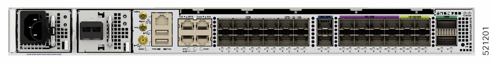
The Cisco N540-FH-CSR-SYS router has the following hardware features:

  • 8 Common Public Radio Interface (CPRI) Ports

  • 2 x 10G/25G TSN ports

  • 8 x 1G/10G ports

  • 4 x 1G/10G/25G SFP+ ports

  • 2 x 100G QSFP ports

  • 4 x CPRI/1G/10G ports

The Cisco N540-FH-AGG-SYS router has the following hardware features:
  • 24 x TSN or CPRI or 25G/10G/1G ports

  • 4x100G QSFP ports

Figure 1. Cisco N540-FH-CSR-SYS
Figure 2. Cisco N540-FH-AGG-SYS

Interface Naming

The following table shows the interface naming of the Cisco N540-FH-CSR-SYS variant:


Caution


On port numbers 12 and 13 after initial bring up, if you perform multiple port shutdown and no shutdown configurations, it may result in a bad state of corrupting the packets (for example it affects, Ethernet, CPRI, or any protocol packets). It also affects any other protocols using these ports as the forwarding path.

Consider using the port numbers 14 to 25, for 25G core functionality, instead of port numbers 12 and 13.


Table 1. Port Numbering

CPRI ports

CPRI/1G/10G ports

10/25G TSN

1G/10G ports

1G/10G/25G ports

100G ports

1

to

7

9

11

13

15

to

21

9

11

27

0

6

8

10

12

14

20

8

10

26

The following table shows the interface naming of the Cisco N540-FH-AGG-SYS variant:

Table 2. Port Numbering

CPRI/1G/10G/25G TSN Ports

100G Ports

0 to 23

24 to 27

The interface-path-id is rack/ slot/ module/ port. The slashes between values are required as part of the notation.


Note


Dual-Rate functionality is supported only with the supported SFP.
Table 3. Maximum Number of Interfaces for Cisco N540-FH-CSR-SYS variant

Category

Maximum Port Number Interface

Port Number

1GE

16

0/8-0/11,0/14-0/25

10GE

18

0/8-0/25

25GE

6

0/12-0/13, 0/22-0/25

100GE

2

0/26-0/27

CPRI

12

0/0-0/11

Table 4. Maximum Number of Interfaces for Cisco N540-FH-AGG-SYS variant

Category

Maximum Port Number Interface

Port Number

1GE

24

0-23

10GE

24

0-23

25GE

24

0-23

100GE

4

24-27

CPRI

24

0-23

Network Timing Interfaces

  • BITS input or output—The BITS interfaces support clock recovery from either a T1 at 1.544MHz or an E1 at 2.048MHz, configurable by software. BITS interface is provided through a standard RJ-48 connector on the front panel.

  • 1PPS input or output and ToD input or output—This shielded RJ-45 interface is used for input or output of time-of-day (ToD) and 1PPS pulses. ToD format includes both NTP and IEEE 1588-2008 time formats.

The same RS422 pins for 1PPS and TOD are shared between input and output directions. The direction for each can be independently configurable through software.

Use an SMB connector on the front panel for the following:

  • GPS 10Mhz input and output—10MHz input for GPS synchronization.

  • GPS 1 PPS input and output—1 PPS input for GPS synchronization.

GNSS Receiver

The chassis has in-built GNSS receiver with ports present at the front panel.

GNSS Module RF Input Requirements

  • For optimal performance, the GNSS module requires an active GPS/GNSS antenna with built-in Low-Noise Amplifier (LNA). The antenna LNA amplifies the received satellite signals for two purposes:
    • Compensation of losses on the cable

    • Lifting the signal amplitude to the suitable range for the receiver frontend

    The Amplification required is 22dB gain + cable/connector loss + Splitter signal loss.

    The recommended range of LNA gain (minus all cable and connector losses) at the connector of the receiver module is 22dB to 30dB with a minimum of 20dB and a maximum of 35dB.

  • GNSS module provides 5V to the active antenna through the same RF input.

  • Surge requirement:

    • GNSS modules have built-in ESD protections on all pins, including the RF-input pin. However, additional surge protection may be required if rooftop antennas are to be connected, to meet the regulations and standards for lightning protection of countries where the end-product is installed.

    • A lightning protection must be mounted at the place where the antenna cable enters the building. The primary lightning protection must be capable of conducting all potentially dangerous electrical energy to PE.

    • Surge arrestors should support DC-pass and suitable for the GPS frequency range (1.575GHz) with low attenuation.

  • Antenna Sky visibility:

    • GPS signals can only be received on a direct line of sight between antenna and satellite. The antenna must have a clear view of the sky. For proper timing, minimum of four satellites should be locked.

      Note


      The antenna terminal should be earthed at the building entrance in accordance with the ANSI/NFPA 70, the National Electrical Code (NEC), in particular Section 820.93, Grounding of Outer Conductive Shield of a Coaxial Cable.
  • Use a passive splitter if more than one GNSS modules are fed from a single antenna.


Note


The splitter should have all the RF ports capable of DC-pass, if the antenna needs to feed power from GNSS module.

For information on pinout, see GPS Port Pinouts.

External Alarm Inputs

The router supports four dry contact alarm inputs through an RJ-45 jack at the rear panel.

  • Normally Open—indicates that no current flows through the alarm circuit and the alarm is generated when the current is flowing.

Each alarm input can be provisioned as critical, major, or minor.

Console

The RS232 console port provides transmission (Tx), reception (Rx), and ground (Gnd).

USB Port

USB Type-A Receptacle

USB port is used for connecting USB devices and can be used to boot from the USB devices. It can be used to transfer files, logs, and so on between the router and the USB device.

USB Console

A single USB 2.0 Type-A receptacle on the front panel of the router provides console access to ROMMON, Cisco IOS-XR, and diagnostics. While it uses the Type-A connector, it operates as a USB peripheral only for connection to an external host computer. This interface requires the use of a Type-A to Type-A connector instead of a standard USB cable.


Note


Use of the USB console is mutually exclusive of the RS232 console port. This interface requires the use of a Type-A to Type-A USB cable.

Online Insertion and Removal

The router supports the following Online Insertion and Removal (OIR) operations:

  • When an SFP is removed, there is no effect on traffic flowing on other ports.

  • When an SFP is installed, the system initializes that port for operation based on the current configuration. If the inserted SFP is incompatible with the current configuration of that port, the port does not become operational until the configuration is updated.

  • When both power supplies are installed and active, the load may be shared between them or a single PSU supports the whole load. When a power supply is not working or the input cable is removed, the remaining power supply takes the entire load without disruption.

  • N540-FH-AGG-SYS supports OIR of six fan trays from rear side. The system supports single fan failure and during single fan failure all other fans run at full speed.