Cisco NCS 1010 Overview

This chapter provides an overview for Cisco NCS 1010.

Table 1. Feature History

Feature Name

Release Information

Description

LC Ports on OLT and ILA Line Cards

Cisco IOS XR Release 7.10.1

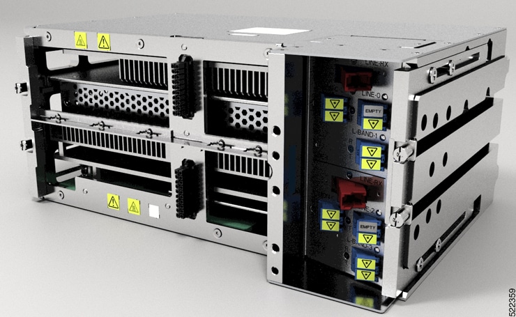
The new OLT and ILA line cards introduce LC ports on their faceplates. These LC ports enable you to directly connect the breakout or multiplexer/demultiplexer modules for degree interconnect or Add/Drop options. The following are the new PIDs introduced for the OLT and ILA line cards:

  • NCS1K-E-OLT-C

  • NCS1K-E-OLT-L

  • NCS1K-E-OLT-R-C

  • NCS1K-E-ILA-R-C

  • NCS1K-E-ILA-2R-C

Cisco NCS 1010 Overview

Cisco NCS 1010 is a next-generation optical line system optimized for ZR/ZR+ WDM router interfaces. Its salient features are:

  • Provides point-to-point connectivity between routers with WDM interfaces.

  • Multiplexes the signals received from multiple routers over a single fiber.

  • With one MPO port, it can be scaled to 8 Degree but if needed node can be scaled to higher than 8 degree, using more EXP MPO ports.

  • Caters to C-band WDM transmission to maximize capacity, and can be enhanced to C+L combined band in the future.

Cisco NCS 1010 is a 3RU chassis that has an in-built External Interface Timing Unit (EITU) and the following field-replaceable modules.

  • Controller

  • Two power supply units

  • Two fan trays

  • Fan filter

  • Line card

    The Cisco NCS 1010 chassis supports the following line cards.

    Table 2. Supported Line Cards

    Line Card

    Description

    Release

    NCS1K-OLT-C

    C-band Optical Line Terminal without Raman

    Cisco IOS XR Release 7.7.1

    NCS1K-OLT-R-C

    C-band Optical Line Terminal with Raman

    Cisco IOS XR Release 7.7.1

    NCS1K-ILA-C

    C-band In-Line Amplifier without Raman

    Cisco IOS XR Release 7.7.1

    NCS1K-ILA-R-C

    C-band In-Line Amplifier with one side Raman

    Cisco IOS XR Release 7.7.1

    NCS1K-ILA-2R-C

    C-band In-Line Amplifier with both sides Raman

    Cisco IOS XR Release 7.7.1

    NCS1K-OLT-L

    L-band Optical Line Terminal without Raman

    Cisco IOS XR Release 7.9.1

    NCS1K-ILA-L

    L-band In-Line Amplifier without Raman

    Cisco IOS XR Release 7.9.1

    NCS1K-E-OLT-C

    C-band Optical Line Terminal without Raman, Enhanced

    Cisco IOS XR Release 7.10.1

    NCS1K-E-OLT-R-C

    C-band Optical Line Terminal with Raman, Enhanced

    Cisco IOS XR Release 7.10.1

    NCS1K-E-OT-L

    L-band Optical Line Terminal without Raman, Enhanced

    Cisco IOS XR Release 7.10.1

    NCS1K-E-ILA-R-C

    C-band In-Line Amplifier with East-facing Raman, Enhanced

    Cisco IOS XR Release 7.10.1

    NCS1K-E-ILA-2R-C

    C-band In-Line Amplifier with both sides Raman, Enhanced

    Cisco IOS XR Release 7.10.1

    NCS1K-E-ILA-R-C-2

    C-band In Line Amplifier with West-facing Raman, Enhanced

    Cisco IOS XR Release 7.11.1

For more information about the Cisco NCS 1010 chassis, see Cisco NCS 1010 Data Sheet.

Figure 1. Cisco NCS 1010 Front View
Figure 2. Cisco NCS 1010 Rear View

The airflow on Cisco NCS 1010 is front to back. Cool air enters the chassis through the fan trays and exhausts through the rear end of the chassis.

Figure 3. Airflow in Cisco NCS 1010

OLT-C Line Card

The C-band Optical Line Terminal without Raman (OLT-C) line card includes the following features:

  • 25-dBm line preamplifier True Variable Gain (TVG) Erbium-Doped Fiber Amplifier (EDFA) with two switchable gain ranges

  • Dedicated amplification of the odd and even add channels through an embedded Fixed Gain (FG) EDFA

  • 23-dBm line boost-amplifier TVG EDFA single gain range

  • Dedicated EDFA for noise loading

  • Embedded Optical Time Domain Reflectometer (OTDR) for line RX and TX monitoring

  • 37 ports Optical Channel Monitoring (OCM)

  • Dedicated Tunable Laser (TL) enabling Connection Verification (CV) and patch cord discovery features

  • Up to 30 EXP ports

  • Embedded Optical Service Channel at Fast Ethernet (FE)

  • Multiplexing and demultiplexing of odd and even channels

  • C+L combiner for multiplexing and demultiplexing L-band channels

  • 2x2 switch to reverse transmit direction of Optical Service Channel (OSC)-C

  • Fiber reflectors to support fiber end detection by OTDR

Figure 4. Front View of OLT-C Line Card

For details of the OLT-C line card ports, see Front View of the OLT-C Line Card Faceplate.

Figure 5. Perspective View of OLT-C Line Card

OLT-R-C Line Card

The C-band Optical Line Terminal with Raman (OLT-R-C) line card includes the features of the OLT-C line card along with the Raman amplifier.

The following are the features of the Raman amplifier:

  • Five different pump wavelengths for supporting C+L Raman amplification

  • Embedded Distributed Feedback (DFB) laser at 1568.77 nm (class 1M) to be used for optical safety (link continuity)

  • Full monitoring of pumps, DFB laser and signal power

  • Raman pump back-reflection detector

  • Meets class 1M Laser safety.

  • Additional Photodiode (PD) to monitor remnant pump power at the far end

Figure 6. Front View of OLT-R-C Line Card

For details of the OLT-R-C line card ports, see Front View of the OLT-R-C Line Card Faceplate.

Figure 7. Perspective View of OLT-R-C Line Card

OLT-L Line Card

Table 3. Feature History

Feature Name

Release Information

Description

NCS1K-OLT-L Line Card

Cisco IOS XR Release 7.9.1

The new NCS1K-OLT-L line card for the NCS 1010 optical line system performs the add/drop function for the L-band traffic. The OLT-L card acts as expansion equipment for the OLT-C units and connects to the L-band expansion port in the OLT-C unit. By supporting L-band traffic, the OLT-L line card improves fiber utilization by enabling the existing OLT-C node to send both C-band and L-band traffic.

The OLT-L line card connects to the L-band expansion ports in the OLT-C unit to add, drop, and route the L-band traffic in the existing fiber. This card cannot be deployed as a standalone unit. It can be used as an expansion equipment for both variants of the OLT-C unit. This card enhances the fiber capacity of the existing OLT-C nodes to send both C- and L-band traffic. Supporting L-band traffic, this unit expands the C-band only nodes to C+L-band nodes.

The L-band Optical Line Terminal (OLT-L) line card includes the following features:

  • 25-dBm line preamplifier True Variable Gain (TVG) Erbium-Doped Fiber Amplifier (EDFA) with two switchable gain ranges

  • Dedicated amplification of the odd and even add channels through an embedded Fixed Gain (FG) EDFA

  • 24.5-dBm line boost-amplifier TVG EDFA single gain range

  • 15-dBm ADD-side boost-amplifier TVG EDFA with single gain range of 16 dB

  • Dedicated EDFA for noise loading

  • 37 ports Optical Channel Monitoring (OCM)

  • Dedicated Tunable Laser (TL) enabling Connection Verification (CV) and patch cord discovery features

  • Up to 30 EXP ports

  • Embedded Optical Service Channel at Fast Ethernet (FE) at 184.45 THz (1625.33 nm)

  • Multiplexing and demultiplexing of odd and even channels

  • 2x2 switch to reverse send direction of Optical Service Channel OSC-L.

Figure 8. Front View of OLT-L Line Card

For details of the OLT-L line card ports, see Front View of the OLT-L Line Card Faceplate.

Figure 9. Perspective View of OLT-L Line Card

ILA-C Line Card

The C-band In Line Amplifier without Raman (ILA-C) line card includes the following features:

  • Two independent TVG EDFA block, covering full operative gain ranging 8–36 dB

  • Each EDFA block can provide up to 23dBm output power

  • Dynamic Gain Equalization (DGE) embedded capability to compensate for line tilt and ripple

  • Embedded OTDR for line1/2-RX/TX monitoring

  • Four-ports OCM for channels monitoring

  • Embedded Optical Service Channel at Fast Ethernet (FE)

  • C+L combiner for multiplexing/demultiplexing L-band channels

  • Dedicated ports for amplifiers output monitoring

  • 2x2 switch to reverse transmit direction of OSC-C for both directions

  • Fiber reflectors to support fiber end detection by OTDR

Figure 10. Front View of ILA-C Line Card

For details of the ILA-C line card ports, see Front View of the ILA-C Line Card Faceplate

Figure 11. Perspective View of ILA-C Line Card

ILA-R-C Line Card

The C-band In Line Amplifier with Raman (ILA-R-C) line card includes the features of ILA-C and Raman amplifier.

Figure 12. Front View of ILA-R-C Line Card

For details of the ILA-R-C line card ports, see Front View of the ILA-R-C Line Card Faceplate.

Figure 13. Perspective View of ILA-R-C Line Card

ILA-2R-C

The C-band In-Line Amplifier with two Raman (ILA-2R-C) line card includes the features of the ILA-C and Raman amplifier.

Figure 14. Front View of ILA-2R-C Line Card

For details of the ILA-2R-C line card ports, see Front View of the ILA-2R-C Line Card Faceplate.

Figure 15. Perspective View of ILA-2R-C Line Card

ILA-L Line Card

Table 4. Feature History

Feature Name

Release Information

Description

NCS1K-ILA-L Line Card

Cisco IOS XR Release 7.9.1

The new NCS1K-ILA-L line card for the NCS 1010 optical line system amplifies L-band traffic. The ILA-L card acts as expansion equipment for the ILA-C units and connects to the L-band expansion port in the ILA-C unit. The ILA-L enables sending the low-loss L-Band through the existing ILA-C node to enhance the fiber capacity and effectively upgrade the C-band only node to a C+L band node.

The ILA-L must always be connected to the L-band expansion ports in the ILA-C unit to amplify the L-band traffic that is traveling together with the C-band traffic in the fiber. The ILA-L unit cannot be deployed as standalone. It can always be used as an expansion equipment for all variants of the ILA-C unit, with or without Raman amplification in one or both direction. The Raman module in the ILA-C unit provides amplification for both C- and L-band signals in long-distance transmission.

The L-band In Line Amplifier (ILA-L) line card includes the following features:

  • Two independent TVG EDFA block, covering full operative gain ranging 10.8–32.8 dB

  • Each EDFA block can provide up to 24.5-dBm total output power

  • Dynamic Gain Equalization (DGE) embedded capability to compensate for line tilt and ripple

  • Four-ports OCM for channels monitoring

  • Embedded Optical Service Channel at Fast Ethernet (FE)

  • Dedicated ports for amplifiers output monitoring

  • 2x2 switch to reverse transmit direction of OSC-L for both directions

Figure 16. Front View of ILA-L Line Card

For details of the ILA-L line card ports, see Front View of the ILA-L Line Card Faceplate

Figure 17. Perspective View of ILA-L Line Card

E-OLT-C Line Card

The C-band Optical Line Terminal without Raman, Enhanced (E-OLT-C) line card includes the following features:

  • 25-dBm line preamplifier True Variable Gain (TVG) Erbium-Doped Fiber Amplifier (EDFA) with two switchable gain ranges

  • Dedicated amplification of the odd and even add channels through an embedded Fixed Gain (FG) EDFA

  • 23-dBm line boost-amplifier TVG EDFA single gain range

  • Dedicated EDFA for noise loading

  • Embedded Optical Time Domain Reflectometer (OTDR) for line RX and TX monitoring

  • 37 ports Optical Channel Monitoring (OCM)

  • Dedicated Tunable Laser (TL) enabling Connection Verification (CV) and patch cord discovery features

  • Up to 30 EXP ports

  • Embedded Optical Service Channel at Fast Ethernet (FE)

  • Multiplexing and demultiplexing of odd and even channels

  • C+L combiner for multiplexing and demultiplexing L-band channels

  • 2x2 switch to reverse transmit direction of Optical Service Channel (OSC)-C

  • Fiber reflectors to support fiber end detection by OTDR

Figure 18. E-OLT-C Line Card
E-OLT-C Line Card Ports
Figure 19. Front View of E-OLT-C Line Card
Front View of E-OLT-C Line Card
Figure 20. Perspective View of E-OLT-C Line Card
Perspective View of E-OLT-C Line Card

E-OLT-R-C Line Card

The C-band Optical Line Terminal with Raman, Enhanced (E-OLT-R-C) line card includes the features of the OLT-C line card along with the Raman amplifier.

The following are the features of the Raman amplifier:

  • Five different pump wavelengths for supporting C+L Raman amplification

  • Embedded Distributed Feedback (DFB) laser at 1568.77 nm (class 1M) to be used for optical safety (link continuity)

  • Full monitoring of pumps, DFB laser and signal power

  • Raman pump back-reflection detector

  • Meets class 1M Laser safety.

  • Additional Photodiode (PD) to monitor remnant pump power at the far end

Figure 21. E-OLT-R-C Line Card
E-OLT-R-C Line Card
Figure 22. Front View of E-OLT-R-C Line Card
Front View of E-OLT-R-C Line Card
Figure 23. Perspective View of E-OLT-R-C Line Card
Perspective View of E-OLT-R-C Line Card

E-OLT-L Line Card

The L-band Optical Line Terminal, Enhanced (E-OLT-L) line card includes the following features:

  • 25-dBm line preamplifier True Variable Gain (TVG) Erbium-Doped Fiber Amplifier (EDFA) with two switchable gain ranges

  • Dedicated amplification of the odd and even add channels through an embedded Fixed Gain (FG) EDFA

  • 24.5-dBm line boost-amplifier TVG EDFA single gain range

  • 15-dBm ADD-side boost-amplifier TVG EDFA with single gain range of 16 dB

  • Dedicated EDFA for noise loading

  • 37 ports Optical Channel Monitoring (OCM)

  • Dedicated Tunable Laser (TL) enabling Connection Verification (CV) and patch cord discovery features

  • Up to 30 EXP ports

  • Embedded Optical Service Channel at Fast Ethernet (FE) at 184.45 THz (1625.33 nm)

  • Multiplexing and demultiplexing of odd and even channels

  • 2x2 switch to reverse send direction of Optical Service Channel OSC-L.

Figure 24. E-OLT-L Line Card
E-OLT-L Line Card
Figure 25. Front View of E-OLT-L Line Card
Front View of E-OLT-L Line Card
Figure 26. Perspective View of E-OLT-L Line Card
Perspective View of E-OLT-L Line Card

E-ILA-R-C Line Card

The C-band In Line Amplifier with Raman, Enhanced (E-ILA-R-C) line card includes the features of E-ILA-C and Raman amplifier.

Figure 27. E-ILA-R-C Line Card
E-ILA-R-C Line Card
Figure 28. Front View of E-ILA-R-C Line Card
Front View of E-ILA-R-C Line Card

For details of the E-ILA-R-C line card ports, see Front View of the E-ILA-R-C Line Card Faceplate.

Figure 29. Perspective View of E-ILA-R-C Line Card
Perspective View of E-ILA-R-C Line Card

E-ILA-2R-C Line Card

The C-band In-Line Amplifier with two Raman, Enhanced (E-ILA-2R-C) line card includes the features of the E-ILA-C and Raman amplifier.

Figure 30. E-ILA-2R-C Line Card
E-ILA-2R-C Line Card
Figure 31. Front View of E-ILA-2R-C Line Card
Front View of E-ILA-2R- C Line Card

For details of the E-ILA-R-C line card ports, see Front View of the E-ILA-2R-C Line Card Faceplate.

Figure 32. Perspective View of E-ILA-2R-C Line Card
Perspective View of E-ILA-2R-C Line Card

E-ILA-R-C-2 Line Card

Table 5. Feature History

Feature Name

Release Information

Description

NCS1K-E-ILA-R-C-2 Line Card

Cisco IOS XR Release 7.11.1

NCS1K-E-ILA-R-C-2 line card is a new addition to the NCS 1010 ILA line cards family. With an inbuilt West-facing Raman amplifier, it amplifies the C-band and C+L-band traffic received from the west direction.

The C-band In Line Amplifier with West-facing Raman, Enhanced (E-ILA-R-C-2) line card includes the features of ILA-C and Raman amplifier.

Figure 33. E-ILA-R-C-2 Line Card
E-ILA-R-C-2 Line Card
Figure 34. Front View of E-ILA-R-C-2 Line Card
Front View of E-ILA-R-C-2 Line Card

For details of the E-ILA-R-C line card ports, see Front View of the E-ILA-R-C-2 Line Card Faceplate.

Figure 35. Perspective View of E-ILA-R-C-2 Line Card
Perspective View of E-ILA-R-C-2 Line Card

External Interface Timing Unit

The External Interface Timing Unit (EITU) manages the control plane interfaces and includes all user external interfaces (timing and management). It is connected to the controller with a redundant 10G Ethernet bus.

Figure 36. Front View of EITU

The following is the list of the available user interfaces:

1

Coaxial connector for GPS antenna RF input (with +5V antenna power, if necessary) (1x)

2

Console/Universal Asynchronous Receiver/Transmitter (UART) Interface (1x)

3

SFP for 1GE optical PTP port (1588 and SyncE)

(2x)

4

SFP for 1GE optical User Data Channels (UDC) (2x)

5

USB 2.0 type A, 1.8A max at 5V/12V (with Cisco NCS 1000 Breakout Patch Panel support) (3x)

Note


The USB ports in the EITU do not support USB drives; they only support passive optical devices from Cisco, such as breakout modules and mux/demux patch panels. If you want to install the operating system or copy files to and from the system, use the USB 3.0 ports labeled "Boot" on the controller cards.

6

Coaxial connector for 10MHz sync signal (bidirectional) (1x)

7

Coaxial connector for 1PPS sync signal (bidirectional) (1x )

8

RJ45 for 1588 TOD (1x)

9

10/100/1000 RJ-45 Ethernet management ports and Interconnection Link (ILINK) (3x)

Supported Controller Cards

Table 6. Feature History

Feature Name

Release Information

Description

NCS1K10-CNTLR-B-K9 Controller Card

Cisco IOS XR Release 7.10.1

The new NCS1010-CTLR-B-K9 controller card for the NCS 1010 optical line system supports a default baud rate of 9600 bps on the RS232 console port. It runs on BIOS version 4.40 and later.

The Cisco NCS 1010 supports the following controller cards:

  • NCS1K10-CNTLR-K9

    The NCS1K10-CNTLR-K9 controller card supports a default of 115200 bps baud rate on the RS232 console port. For details of the NCS1K10-CNTLR-K9 controller card, see Front View of the NCS1010-CNTLR-K9 Controller

  • NCS1K10-CTLR-B-K9

    The NCS1K10-CNTLR-B-K9 controller card supports a default of 9600 bps baud rate on the RS232 console port. For details of the NCS1K10-CNTLR-B-K9 controller card, see Front View of the NCS1010-CTLR-B-K9 Controller

Cisco NCS 1010 LEDs

Cisco NCS 1010 includes multiple LEDs to determine the overall state of the system and to verify the status of specific connections, ports, and system components.

Controller LEDs

Thecontroller (NCS1010-CNTLR-K9 and NCS1010-CTLR-B-K9) units have five LEDs to indicate the system status and the status of the components.

Figure 37. Front View of the NCS1010-CNTLR-K9 Controller
Figure 38. Front View of the NCS1010-CTLR-B-K9 Controller
Front View of the NCS1010-CTLR-B-K9 Controller

1

Bluetooth Low Energy (BLE) Status LED

2

System Status LED

3

Fan Status LED

4

Power Supply Status LED

5

Attention LED

Table 7. Status of the Controller LEDs

LED

Default Status of LED (At the time of Power On and when the System is not Up)

Color

Status

BLE LED

Off

Off

Not supported.

System LED (during controller boot up)

Red

Red

Indicates that the controller unit is powering ON.

Red (flashing slowly)

Indicates BIOS loading.

Yellow (flashing slowly)

Indicates operating system loading.

Red (flashing fast)

Indicates secure boot failure. Replace the controller.

Yellow (flashing fast)

Indicates that the controller unit is not seated properly. Remove and replace the controller properly.

System LED (controller is operational)

Red

Red

Indicates a major or critical alarm.

Yellow

Indicates a minor alarm.

Green

The module is operational and has no active alarms.

Fan LED

Red

Green

Indicates all fans present in the chassis are in working condition.

Red

Indicates either a fan is missing from its slot or is faulty.

PSU LED

Red

Green

Indicates all PSUs' present in the chassis are in working condition.

Red

Indicates either a PSU is missing from its slot or is faulty, or there is no input power.

Attention LED

Off

Blue

Used to identify a specific chassis in a rack or room. This is used for troubleshooting purposes such as replacing the fiber and field-replaceable units. It can be controlled through the software CLI.

Use the following command to activate this LED, manually:

hw-module attention-led location 0/RP0/CPU0

Line Card LEDs

The OLT line cards (OLT-C, OLT-R-C, OLT-L) have two LEDs to indicate the line port alarm status, two LEDs indicating the add/drop port alarm status, and four LEDS indicating the MPO connector ports alarm status. The MPO port LEDs represent multiple ports.


Note


The OLT line cards (E-OLT-C, E-OLT-R-C, E-OLT-L) do not have LEDs to indicate the line port alarm status.


Figure 39. Front View of the OLT-C Line Card Faceplate
Figure 40. Front View of the OLT-R-C Line Card Faceplate

The OLT-L line card has only one LED to indicate the line port alarm status, two LEDs indicating the add/drop port alarm status, and four LEDS indicating the MPO connector ports alarm status. The MPO port LEDs represent multiple ports.

Figure 41. Front View of the OLT-L Line Card Faceplate

1

Line port LEDs

2

Add/Drop port LEDs

3

MPO connector LEDs

The ILA line cards (ILA-C, ILA-R-C, ILA-2R-C, ILA-R-C, ILA-2R-C, ILA-R-C-2) have four LEDs to indicate the line port alarm status.

Figure 42. Front View of the ILA-C Line Card Faceplate
Figure 43. Front View of the ILA-R-C Line Card Faceplate
Figure 44. Front View of the ILA-2R-C Line Card Faceplate
Figure 45. Front View of the E-ILA-R-C Line Card Faceplate
Front View of the E-ILA-R-C Line Card Faceplate
Figure 46. Front View of the E-ILA-2R-C Line Card Faceplate
Front View of the E-ILA-2R-C Line Card Faceplate
Figure 47. Front View of the E-ILA-R-C-2 Line Card Faceplate
Front View of the E-ILA-R-C-2 Line Card Faceplate

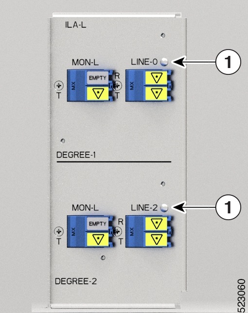
The ILA-L line card has two LEDs to indicate the line port alarm status.

Figure 48. Front View of the ILA-L Line Card Faceplate

1

Line port LEDs

Table 8. Status of the Line Card LEDs

LED

Color

Status

Line card LED

Red

Indicates major and critical alarms, which could be a traffic impacting situation.

Orange

Indicates a minor alarm.

Green

Indicates that the module is operational and has no alarm.

PSU LED

The PSU has one LED to indicate its status.

Figure 49. Front View of AC PSU
Figure 50. Front View of DC PSU

1

LED

The following table has details of the PSU LED:

Table 9. Status of the PSU LED

LED

color

Status

PSU LED

Amber

Indicates that there is no input to the PSU, provided the other PSU is working.

Off

Both PSUs do not have input.

Green

Indicates that the input to the PSU is valid.

Fan Tray LED

The fan tray has one LED to indicate its status.

Figure 51. Front View of the Fan Tray

1

Fan tray LED

The following table has details of the fan tray LED:

Table 10. Status of the Fan Tray LED

LED

Color

Status

Fan LED

Amber

Indicates that the fan speed is out of expected range such as fan is not rotating. Also, indicates that the fan speed is not readable.

Red

Indicates a fault in the fan tray.

Green

Indicates that the fan tray is working fine.

EITU LEDs

The EITU has 12 LEDs indicating the status of its ports.

Figure 52. Front View of the EITU

1

Ethernet Copper Ports LEDs

2

Ethernet Optical SFP Ports LEDs

3

GPS LED

4

SYNC LED

Table 11. Status of the EITU LEDs

LED

Color

Status

GPS LED

Green

GPS phase is locked.

Yellow

GPS is enabled.

Off

GPS is not enabled.

Red

GPS is used.

Sync LED

Green

Time core is synchronized to an external source including IEEE1588.

Flashing green

System is in Synchronous Ethernet mode.

Amber

Acquiring state or Holdover: Time core is in acquiring state or holdover mode.

Off

Time core clock synchronization is disabled or in free-running state.

Ethernet Copper Ports (MGMT 0/1/2) LEDs

Green

The link is ON.

Yellow

Link is up but without traffic.

Flashing yellow

Link is up but with traffic.

Ethernet Optical SFP Ports (PTP0/1, UDC 0/1) LEDs

Green

Indicates the presence of duplex or traffic collision.

Yellow

LINK is up but without traffic.

Flashing yellow

LINK is up but with traffic.