SSD Module

This chapter contains the following sections:

Introduction to the Solid State Drive in the IR1800 Series

The IR1800 can use a Solid State Drive (SSD). The PID is IRM-SSD-100G.


Note


The SSD can only be supported to a maximum temperature of 60C / 0LFM.

The following graphic shows an SSD module.

Figure 1. SSD Module

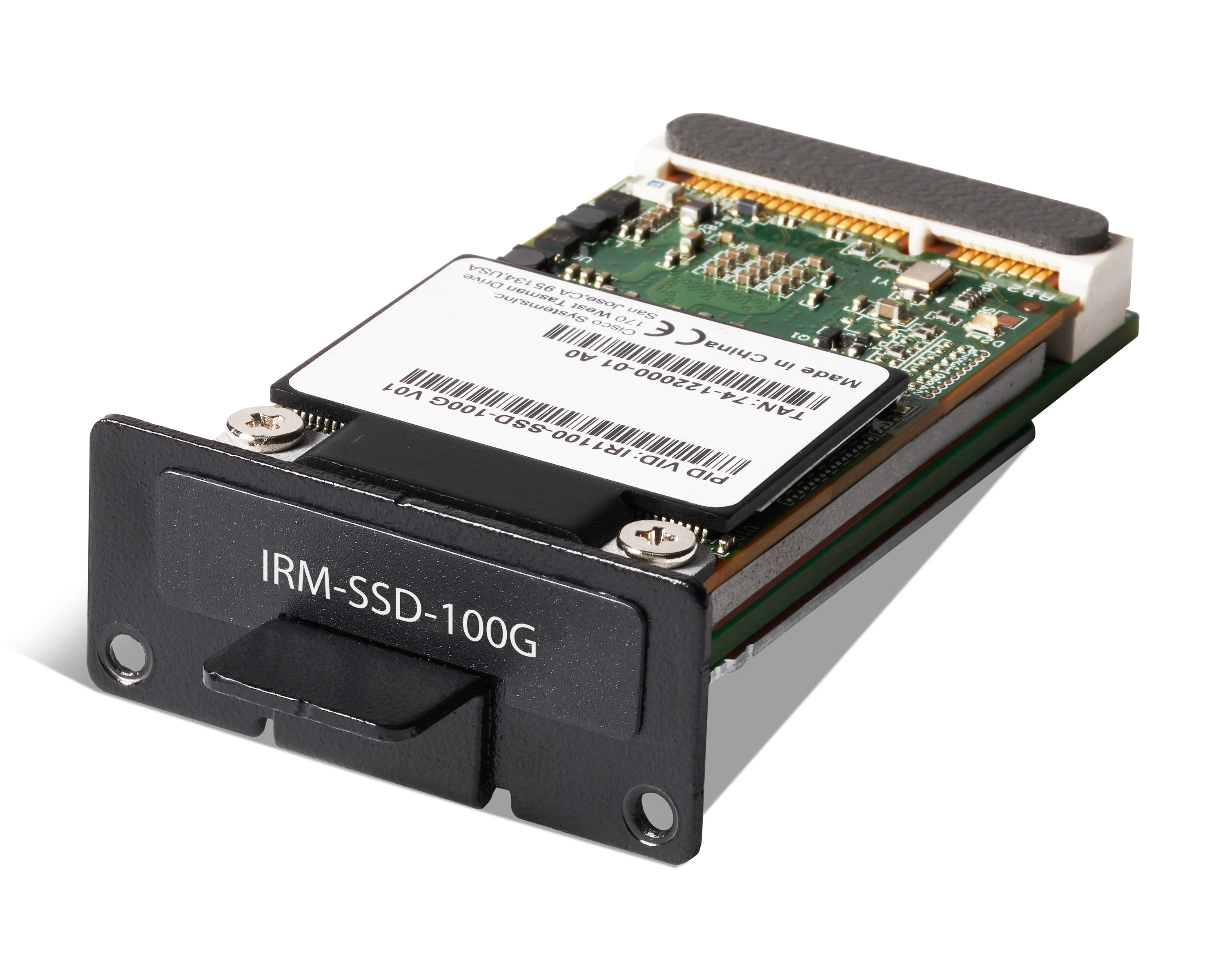
The highlights of the SSD module are:

  • Provides an additional 100 GB of additional Flash memory storage.

  • Provides space to store application data for Cisco IOx.

  • The SSD is a Field Replaceable Unit, but is not hot-swappable.

Installing an SSD Module

This section provides an overview of an SSD module installation.


Caution


  • Ensure that you are using proper static discharge techniques such as a wrist strap and static mat.

  • Ensure that the device is powered down before performing the removal or installation of an SSD module.


Before you begin

Ensure the device is powered off.

Procedure


Step 1

Remove the two screws (1 ) holding the cover of the SSD module slot as shown in the following figure. Retain these screws for future use.

Figure 2. SSD Module Cover

1

Screws

Step 2

Insert the SSD module into the slot in the panel such that the previously removed screws (1 ) align with the screw holes (2 ), as shown in the following figure.

Figure 3. Module Placement

1

Screws

2

Screw holes

Step 3

After the module is properly inserted, tighten the module plate to the panel with the two screws. The screws should be torqued to 2-3 in-lb (0.2-0.3 Newton meter).

Step 4

The installation is now complete.