Metrics for Assurance Monitoring

Metrics for Assurance monitoring refers to Assurance-related metrics collected per network application, for flows forwarded through specific interfaces, to support Assurance monitoring by Cisco DNA Center. FNF provides a pair of record types (for IPv4 and IPv6) to collect this data. Monitoring for Assurance is optimized to provide better than typical performance for FNF monitors.

Feature Information for Metrics for Assurance Monitoring

The following table provides release information about the feature or features described in this module. This table lists only the software release that introduced support for a given feature in a given software release train. Unless noted otherwise, subsequent releases of that software release train also support that feature.

Use Cisco Feature Navigator to find information about platform support and Cisco software image support. To access Cisco Feature Navigator, go to www.cisco.com/go/cfn. An account on Cisco.com is not required.
Table 1. Feature Information for Metrics for Assurance Monitoring

Feature Name

Releases

Feature Information

Metrics for Assurance Monitoring

Cisco IOS XE Gibraltar 16.10.1

FNF provides a pair of record types to collect data for Assurance, optimized to provide better than typical performance for FNF monitors.

Information About Metrics for Assurance Monitoring

Overview

DNA Center Assurance

Cisco DNA Center Assurance collects and analyzes network data to help provide better and more consistent network performance. DNA Center uses Flexible NetFlow (FNF) to collect specific network metrics for Assurance, providing quantitative and qualitative information about devices in the network. The FNF records designed for Assurance-related metrics are specially optimized for improved performance.

FNF provides a pair of record types (for IPv4 and IPv6) to collect data for Assurance. Monitoring Assurance metrics using these dedicated record types is optimized to provide better performance, as compared with typical FNF monitors configured to collect the same metrics. (Modifying the records cancels the dedicated performance enhancements for Assurance, and may prevent attaching a monitor to an interface.)

Manual Configuration

In typical use, DNA Center configures the monitors to collect data for Assurance, without requiring user input. However, it is also possible to use these record types manually.

Metrics Collected for Assurance

Most of the metrics collected for Assurance are metrics that have been available through FNF and other monitor types, but when they are collected specifically for Assurance records, some metrics may behave slightly differently.

Table 2. Metrics

Metric

Information

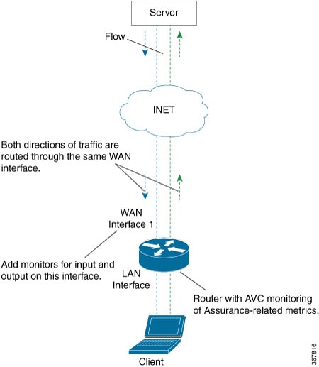
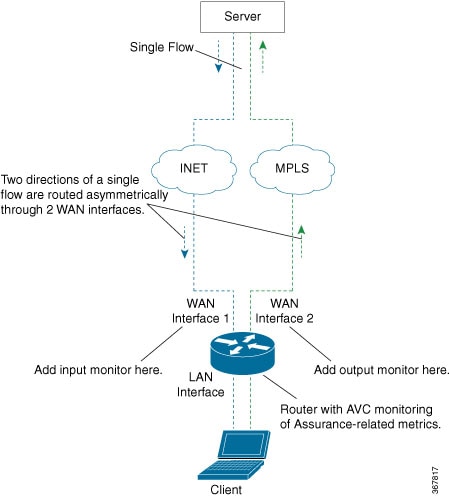
match ipv4/ipv6 version

IPv4/IPv6 version from IPv4/IPv6 header.

[1]

match ipv4/ipv6 protocol

Layer4 protocol from the IPv4/IPv6 header.

match application name

Application ID

match connection client ipv4/ipv6 address

Field name: clientIPv4/IPv6Address

IPv4/IPv6 client address in the IP packet header. The client is the device that triggered the session creation, and remains the same for the life of the session.

[2]

match connection server ipv4/ipv6 address

Field name: serverIPv4/IPv6Address

IPv4/IPv6 server address in the IP packer header. The server is the device that replies to the client, and remains the same for the life of the session.

[2]

match connection server transport port

Field name: serverTransportPort

Server transport port identifier. This may be the source or destination transport port. The server is the device that replies to the client, and remains the same for the life of the session.

[2]

match flow observation point

Field name: observationPointId

Identifier of an observation point unique for each observation domain.

[2]

collect connection initiator

Field name: biflowDirection

Description of the direction assignment method used to assign the Biflow Source and Destination.

[2]

collect flow direction

Direction (ingress/egress) of the flow observed at the observation point.

collect routing vrf input

Field name: ingressVRFID

(Applies only to routers, not wireless controllers)

VRF ID from incoming packets on a router. If a packet arrives on an interface that does not belong to a VRF, a VRF ID of 0 is recorded.

collect wireless client mac address

(Applies only to wireless controllers)

Field name: staMacAddress

The IEEE 802 MAC address of a wireless station (STA).

collect timestamp absolute first

Field name: flowStartMilliseconds

The absolute timestamp of the first packet of the flow.

collect timestamp absolute last

Field name: flowEndMilliseconds

The absolute timestamp of the last packet of the flow.

collect connection new-connections

Field name: connectionCountNew

This information element counts the number of TCP or UDP connections which were opened during the observation period. The observation period may be specified by the flow start and end timestamps.

[2]

collect connection server counter packets long

Field name: serverPackets

Number of layer 4 packets in a flow from the server. The server is the device that replies to the client, and remains the same for the life of the session.

[2]

collect connection server counter bytes network long

Field name: serverOctets

Overall IP packet bytes in a flow from the server. The server is the device that replies to the client, and remains the same for the life of the session.

[2]

collect connection client counter packets long

Field name: clientPackets

Number of layer 4 packets in a flow from the client. The client is the device that triggered the session creation, and remains the same for the life of the session.

[2]

collect connection client counter bytes network long

Overall IP packet bytes from client to server.

[2]

collect connection delay network client-to-server sum

Field name: sumNwkTime

Network delay is the round-trip time between the client and the server, as measured by the observation point, calculated once per session. The value of this information element is the sum of all network delays observed for the sessions of this flow.

[2] [3]

collect connection delay network to-server sum

Field name: sumServerNwkTime

Server network delay is the round-trip time between the observation point and the server, calculated once per session. The value of this information element is the sum of all server network delays observed for the sessions of this flow.

[2] [3]

collect connection client counter packets retransmitted

Field name: retransClientPackets

Number of packets retransmitted by the client.

[2] [3]

collect connection server counter packets retransmitted

Field name: retransServerPackets

Number of packets retransmitted by the server.

[3]

collect connection delay application sum

Field name: sumServerRespTime

The sum of all application delays observed for all responses of the flow.

[2] [3]

collect connection server counter responses

Field name: numRespsCountDelta

Total number of responses sent by the server.

[2] [3]

Notes

  • [1] See Cisco IOS Flexible NetFlow Command Reference.
  • [2] See Cisco AVC Field Definition Guide.
  • [3] This metric can be used in Cisco Performance Monitor record types. It can be used with FNF only as part of the specially optimized Assurance-related records. Attempting to use this metric in a different FNF record type will cause the record to be rejected when attaching it to an interface.

How to Configure Metrics for Assurance Monitoring

Configuring Assurance Monitors Outside of DNA Center

In typical use, DNA Center configures the monitors without requiring additional user input, but it is possible to configure monitors for Assurance-related metrics manually.

Manual methods for monitoring Assurance-related metrics:

Method

Applicable to...

See section...

ezPM profile

Platforms that support ezPM

Not wireless controllers

Configuring Assurance Monitors Using ezPM

Pre-defined FNF records for Assurance

Routers

Wireless controllers

Configuring Assurance Monitors Using Pre-defined FNF Records

Configuring Assurance Monitors Using ezPM

Applicable to: routers, not wireless controllers

The application-assurance ezPM profile makes use of the application performance monitoring (APM) FNF records designed for Assurance-related metrics. Configuring APM with ezPM greatly simplifies the configuration, as compared with working with the FNF records directly.

  1. Configure the ezPM context.

    performance monitor context context-name profile application-assurance

    traffic-monitor assurance-monitor ipv4

    traffic-monitor assurance-monitor ipv6

  2. Attach the context to an interface. The following attaches the performance monitor to an interface, monitoring both input and output.

    interface interface

    performance monitor context context-name

Result

This attaches monitors to the interface to collect Assurance-related metrics.

Example

In the following example, a monitor called apm is attached to the Gigabit Ethernet 1 interface.

performance monitor context apm profile application-assurance
traffic-monitor assurance-monitor ipv4
traffic-monitor assurance-monitor ipv6

interface GigabitEthernet1
performance monitor context apm

Configuring Assurance Monitors Using Pre-defined FNF Records

Applicable to: routers, wireless controllers

ezPM is the preferred method for configuring monitors for Assurance-related metrics, but it is also possible to use the FNF records pre-defined for these metrics. For platforms that do not support ezPM, this is the preferred method.

The FNF records designed for Assurance-related metrics are specially optimized for improved performance.

How to configure on a routing platform


Note


Does not apply to wireless platforms.


  1. Define two flow monitors for assurance-related metrics, one for IPv4 and one for IPv6.

    flow monitor monitor-name-for-ipv4

    cache entries 100000 {Optional. Recommended value depends on platform.}

    record netflow ipv4 assurance

    flow monitor monitor-name-for-ipv6

    cache entries 100000 {Optional. Recommended value depends on platform.}

    record netflow ipv6 assurance

  2. Attach the context to an interface. The following attaches the performance monitor to an interface, monitoring both input and output.

    interface interface

    ipv4 flow monitor monitor-name-for-ipv4 input

    ipv4 flow monitor monitor-name-for-ipv4 output

    ipv6 flow monitor monitor-name-for-ipv6 input

    ipv6 flow monitor monitor-name-for-ipv6 output

Result

This attaches two IPv4 and two IPv6 monitors to the interface for collecting the metrics that are needed for Assurance.

Example

This example defines monitors called assurance-ipv4 and assurance-ipv6, and attaches the monitors to the GigabitEthernet1 interface.

flow monitor assurance-ipv4
cache entries 100000
record netflow ipv4 assurance

flow monitor assurance-ipv6
cache entries 100000
record netflow ipv6 assurance

interface GigabitEthernet1
ipv4 flow monitor assurance-ipv4 input
ipv4 flow monitor assurance-ipv4 output
ipv6 flow monitor assurance-ipv6 input
ipv6 flow monitor assurance-ipv6 output

How to configure on a wireless platform


Note


Does not apply to routing platforms.


  1. Enter the configuration mode for the relevant wireless profile.

    interface policy-name

  2. Define two monitors for the wireless controller, one for IPv4 and one for IPv6.

    flow monitor monitor-name-wlc-for-ipv4

    cache entries 100000 {Optional. Recommended value depends on platform.}

    record wireless avc ipv4 assurance

    flow monitor monitor-name-wlc-ipv6

    cache entries 100000 {Optional. Recommended value depends on platform.}

    record wireless avc ipv6 assurance

  3. Attach the two flow monitors to the wireless profile, including input and output traffic.

    wireless profile policy policy-name

    ipv4 flow monitor monitor-name-for-wireless-ipv4 input

    ipv4 flow monitor monitor-name-for-wireless-ipv4 output

    ipv6 flow monitor monitor-name-for-wireless-ipv6 input

    ipv6 flow monitor monitor-name-for-wireless-ipv6 output

Example

This example defines monitors called assurance-wlc-ipv4 and assurance-wlc-ipv6, and attaches the monitors to a wireless profile.

flow monitor assurance-wlc-ipv4
cache entries 100000
record wireless avc ipv4 assurance

flow monitor assurance-wlc-ipv6
cache entries 100000
record wireless avc ipv6 assurance

wireless profile policy AVC_POL
central association
central switching
ipv4 flow monitor assurance-wlc-ipv4 input
ipv4 flow monitor assurance-wlc-ipv4 output
ipv6 flow monitor assurance-wlc-ipv6 input
ipv6 flow monitor assurance-wlc-ipv6 output
no shutdown

About Attaching the Assurance Monitors to Interfaces

Monitor a Flow on Only One Interface

Monitors for Assurance-related metrics should only see a single flow one time. In the typical symmetric routing scenario, they should monitor the flow on only one interface.

Do not attach monitors for Assurance-related metrics to two separate interfaces that handle both directions of the same flow. Doing so will cause incorrect traffic metrics to be reported. For example, if traffic enters a device on interface A and leaves on interface B, do not attach monitors for Assurance-related metrics to both interfaces A and B.

Typical symmetric routing, with monitors for input and output on the same interface:

Figure 1. Symmetric Routing

Asymmetric Routing

In some cases, such as for asymmetric routing, it might be necessary to attach a monitor for input on one interface, and a monitor for output on another interface.

In some scenarios, a single flow may be routed asymmetrically, with upstream and downstream traffic for the flow occurring on two different interfaces. In this case, place monitors for input and output on two separate interfaces to monitor the complete flow.

Figure 2. Asymmetric Routing

Viewing Details of Assurance Records and Contexts

Overview

After you attach a context to an interface, two show commands can be used to display information about Assurance records or about contexts.

Displaying Structure of the Assurance Record

The following command displays the structure of the pre-defined Assurance records (IPv4 and IPv6):

show fnf record netflow { ipv4 | ipv6} assurance

Displaying Configuration of a Context

The following command displays the full configuration of a specified context.

show performance monitor context context-name configuration

The following output shows the Assurance-related monitoring through an ezPM context called ApmContext, attached to a router interface.

Device#show performance monitor context ApmContext configuration
!===============================================================================
!                Equivalent Configuration of Context ApmContext                !
!===============================================================================
!Exporters
!==========
!
flow exporter ApmContext-1
description performance monitor context ApmContext exporter
destination 64.103.113.128 vrf FNF
source GigabitEthernet2/2/0
transport udp 2055
export-protocol ipfix
template data timeout 300
option interface-table timeout 300
option vrf-table timeout 300
option sampler-table timeout 300
option application-table timeout 300
option application-attributes timeout 300
!
!Access Lists
!=============
!Class-maps
!===========
!Samplers
!=========
!Records and Monitors
!=====================
!
flow record ApmContext-app_assurance_ipv4
description ezPM record
match ipv4 version
match ipv4 protocol
match application name
match connection client ipv4 address
match connection server ipv4 address
match connection server transport port
match flow observation point
collect routing vrf input
collect flow direction
collect timestamp absolute first
collect timestamp absolute last
collect connection initiator
collect connection new-connections
collect connection server counter responses
collect connection delay network to-server sum
collect connection client counter packets retransmitted
collect connection delay network client-to-server sum
collect connection delay application sum
collect connection server counter packets long
collect connection client counter packets long
collect connection server counter packets retransmitted
collect connection server counter bytes network long
collect connection client counter bytes network long
!
!
flow monitor ApmContext-app_assurance_ipv4
description ezPM monitor
exporter ApmContext-1
cache timeout active 60
cache entries 100000
record ApmContext-app_assurance_ipv4
!
!
flow record ApmContext-app_assurance_ipv6
description ezPM record
match ipv6 version
match ipv6 protocol
match application name
match connection client ipv6 address
match connection server transport port
match connection server ipv6 address
match flow observation point
collect routing vrf input
collect flow direction
collect timestamp absolute first
collect timestamp absolute last
collect connection initiator
collect connection new-connections
collect connection server counter responses
collect connection delay network to-server sum
collect connection client counter packets retransmitted
collect connection delay network client-to-server sum
collect connection delay application sum
collect connection server counter packets long
collect connection client counter packets long
collect connection server counter packets retransmitted
collect connection server counter bytes network long
collect connection client counter bytes network long
!
!
flow monitor ApmContext-app_assurance_ipv6
description ezPM monitor
exporter ApmContext-1
cache timeout active 60
cache entries 100000
record ApmContext-app_assurance_ipv6
!
!Interface Attachments
!======================
interface TenGigabitEthernet2/0/0
ip flow monitor ApmContext-app_assurance_ipv4 input
ip flow monitor ApmContext-app_assurance_ipv4 output
ipv6 flow monitor ApmContext-app_assurance_ipv6 input
ipv6 flow monitor ApmContext-app_assurance_ipv6 output

Notes and Limitations

Assurance-related Metrics and Elephant Flows

In networking, especially long flows are termed, “elephant flows,” and can pose a challenge to networking resources.

In a case where a single high-burst flow consumes too many QFP resources, the monitor collecting Assurance metrics might stop collecting qualitative metrics for the flow, to preserve resources for other traffic. No other traffic is affected.

Quantitative metrics are collected fully:

  • Flow packets start time

  • Flow packet end time

  • Packets

  • Bytes

Qualitative metrics are not collected fully:

  • Total network delay sum (in the TCP handshake)

  • Network to-server delay sum (in the TCP handshake)

  • Client packets retransmitted

  • Server packets retransmitted

  • Application delay sum

  • Number of server application responses