Installing and Upgrading Modules

This chapter describes how to install and upgrade modules in the Cisco Catalyst IR8340 Rugged Series Router in the following sections:


Note

Before you perform any module replacement, read Safety Warnings and disconnect power when noted.


Safety Warnings


Warning

Only trained and qualified personnel should be allowed to install, replace, or service this equipment. Statement 1030


Warning

Do not work on the system or connect or disconnect cables during periods of lightning activity. Statement 1001


Warning

Read the installation instructions before connecting the system to the power source. Statement 1004


Warning

Hazardous network voltages are present in WAN ports regardless of whether power to the unit is OFF or ON. To avoid electric shock, use caution when working near WAN ports. When detaching cables, detach the end away from the unit first. Statement 1026


Installing a Network Interface Module in the IR8340 Router

To install a Network Interface Module (NIM) in the IR8340 router, follow these steps:

Before you begin


Note

Before you install the modules to the router, make sure that the router is fully powered off. Every time you insert or remove a module, the router must be powered off first. The power should be resumed after the module is inserted into or removed from the slot.


Procedure


Step 1

Remove the blank faceplate installed at the NIM slot that you intend to use by loosening the two captive screws. Save blank faceplates for future use.

Step 2

Insert the NIM into one of the router NIM slots, as shown in the following figure.

1

Module captive screws (2)

2

NIM module

3

NIM module slots

Step 3

Push the module into place until you feel the edge connector seat securely into the connector on the router backplane.

Step 4

After the module is properly inserted, tighten the module plate to the router with the two captive screws. The screws should be torqued to 5 to 7 in-lbs.

Step 5

Connect the module to the network and re-enable the power to the slot in the router.


Installing Pluggable Modules

To install a pluggable interface module (PIM) in the IR8340 router, follow these steps:

Before you begin


Note

Before you install the modules to the router, make sure that the router is fully powered off. Every time you insert or remove a module, the router must be powered off first. The power should be resumed after the module is inserted into or removed from the slot.


Procedure


Step 1

Remove the blank faceplates installed over the PIM slot that you intend to use by loosening the two captive screws. Save blank faceplates for future use.

Step 2

Slide the blank plate out of the device.

Step 3

Prepare the cellular modem module by inserting the micro SIMs applicable for your modems into the device. Remove the screw (1) holding the access plate in place that covers the sim slots. Use a #1 Phillips screwdriver. The access plate is located on the side of the module, as shown in the following figure:

Step 4

Install your SIMs (1) as shown in the following figure. Make note of the proper slot number and SIM orientation.

Figure 1. SIM Installation

1

Micro SIMs

2

SIM 0 (towards the device)

3

SIM 1 (away from device)

Step 5

Push in each SIM until it clicks into place. When the SIMs are installed, re-attach the access plate previously removed with a #1 Phillips screwdriver. Torque to 2.8 to 3.8 in-lbs.

Note 
Make sure that the cover is properly aligned with the screw hole.
Step 6

If your Pluggable Module has a USB port, make sure that the USB cover is properly installed. Place the USB cover (1) with the plug indentation against the USB port (2). The half circle of the USB cover fits behind the latch lock screw, as shown in the following figure.

Step 7

Tighten the latch lock screw to a torque of 2.8 to 3.8 in-lbs. The following figure shows a completed USB cover installation.

Step 8

Slide the Pluggable Module into the router. The latch lock screw aligns with the screw hole on the front of the router. Push the Pluggable Module all the way into the device until you feel it seat, and then torque the latch lock screw 5 to 7 in-lbs.

1

Module captive screw

2

PIM module

3

PIM module slots

Step 9

Attach your antennas to the ports on the pluggable module. There are different instructions for each antenna type, be sure to consult the antenna documentation for proper orientation and torque to install them.

Step 10

If no antennas are being installed on a port, make sure the caps are installed on the connector.


Installing the mSATA SSD

Mini-SATA, or mSATA, is a low-profile interface connector that enables more effective Serial ATA (SATA) integration in small form-factor drives roughly the size of a business card, such as solid state disks (SSDs).


Note

Make sure that that you are using proper static discharge techniques such as a wrist strap and static mat.

Caution

Make sure that the device is powered down before performing any removal or installation of a module.


Perform the following steps in order to install the module.

Procedure


Step 1

Remove the two captive screws holding the cover of the mSATA slot.

Step 2

Insert the mSATA SSD module into the slot on the router, as shown in the following figure.

1

Module captive screws (2)

2

mSATA module

3

mSATA module slot

Step 3

After the module is properly inserted, tighten the module plate to the router with the two captive screws. The screws should be torqued to 2.3 to 2.9 in-lbs.


Installing SFP Modules

This section describes how to install optional small-form-factor pluggable (SFP) modules in Cisco IR8340 routers to provide optical Gigabit Ethernet connectivity.

For a list of supported SFP SKUs, see Table 1.

The SFP module installs into a slot on the router’s cable side panel. When selected in Cisco IOS software, it is assigned port gigabitethernet 0/0 or 0/1 for WAN or LAN port. The default is the built-in RJ-45 1000 Base-T connector, which is enabled on this port.


Tip

Use the show inventory command at the Cisco IOS prompt to determine whether you are using an SFP certified by Cisco.


Laser Safety Guidelines

Optical SFPs use a small laser to generate the fiber-optic signal. Keep the optical transmit and receive ports covered whenever a cable is not connected to the port.

Installing SFP Modules

To install an SFP module in a Cisco IR8340 router:

Procedure


Step 1

Slide the SFP into the router connector until it locks into position.

Tip 

If the SFP uses a bale-clasp latch, the handle should be on top of the SFP module.

Caution 

Do not remove the optical port plugs from the SFP until you are ready to connect cabling.

Step 2

Connect the network cable to the SFP module.


Removing SFP Modules

To remove an SFP from a Cisco IR8340 router:

Procedure


Step 1

Disconnect all cables from the SFP.

Caution 

The latching mechanism used on many SFPs locks the SFP into place when cables are connected. Do not pull on the cabling in an attempt to remove the SFP.

Step 2

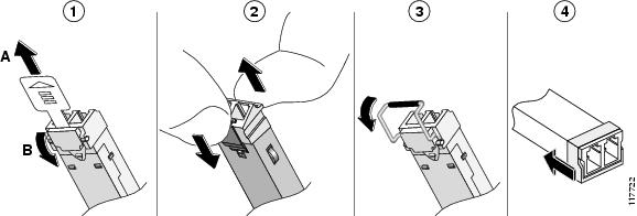
Disconnect the SFP latch (see the following figure).

Note 
SFP modules use various latch designs to secure the module in the SFP port. Latch designs are not linked to SFP model or technology type. For information on the SFP technology type and model, see the label on the side of the SFP.
Figure 2. Disconnecting SFP Latch Mechanisms

1

Sliding latch

3

Bale-clasp latch

2

Swing and slide latch

4

Plastic collar latch

Tip 

Use a pen, screwdriver, or other small straight tool to gently release a bale-clasp handle if you cannot reach it with your fingers.

Step 3

Grasp the SFP on both sides and remove it from the router.