Enterprise Firewall with Application Awareness

Enterprise Firewall with Application Awareness

Table 1. Feature History

Feature Name

Release Information

Feature Description

IPv6 Support for Zone-based Firewall

Cisco IOS XE Catalyst SD-WAN Release 17.11.1a

Cisco vManage Release 20.11.1

This feature adds support for configuring IPv6 Zone-based Firewall (ZBFW) in addition to the existing IPv4 ZBFW. IPv6 is supported for the following scenarios:

Match Traffic Using Custom Applications

Cisco IOS XE Catalyst SD-WAN Release 17.14.1a

Cisco Catalyst SD-WAN Manager Release 20.14.1

Added support for matching traffic using a custom application in a custom-defined application list.

Cisco’s Enterprise Firewall with Application Awareness feature uses a flexible and easily understood zone-based model for traffic inspection, compared to the older interface-based model.

Overview of Enterprise Firewall with Application Awareness

The Enterprise Firewall with Application Awareness uses a flexible and easily understood zone-based model for traffic inspection, compared to the older interface-based model.

A firewall policy is a type of localized security policy that allows stateful inspection of TCP, UDP, and ICMP data traffic flows. Traffic flows that originate in a given zone are allowed to proceed to another zone based on the policy between the two zones. A zone is a grouping of one or more VPNs. Grouping VPNs into zones allows you to establish security boundaries in your overlay network so that you can control all data traffic that passes between zones.

Zone configuration consists of the following components:

  • Source zone—A grouping of VPNs where the data traffic flows originate. A VPN can be part of only one zone.

  • Destination zone—A grouping of VPNs where the data traffic flows terminate. A VPN can be part of only one zone.

  • Firewall policy—A security policy, similar to a localized security policy, that defines the conditions that the data traffic flow from the source zone must match to allow the flow to continue to the destination zone. Firewall policies can match IP prefixes, IP ports, the protocols TCP, UDP, ICMP, and applications. Matching flows for prefixes, ports, and protocols can be accepted or dropped, and the packet headers can be logged. Nonmatching flows are dropped by default. Matching applications are denied.

  • Zone pair—A container that associates a source zone with a destination zone and that applies a firewall policy to the traffic that flows between the two zones.

Matching flows that are accepted can be processed in two different ways:

  • Inspect—The packet's header can be inspected to determine its source address and port. When a session is inspected, you do not need to create a service-policy that matches the return traffic.

  • Pass—Allow the packet to pass to the destination zone without inspecting the packet's header at all. When a flow is passed, no sessions are created. For such a flow, you must create a service-policy that will match and pass the return traffic.

The following figure shows a simple scenario in which three VPNs are configured on a router. One of the VPNs, VPN 3, has shared resources that you want to restrict access to. These resources could be printers or confidential customer data. For the remaining two VPNs in this scenario, only users in one of them, VPN 1, are allowed to access the resources in VPN 3, while users in VPN 2 are denied access to these resources. In this scenario, we want data traffic to flow from VPN 1 to VPN 3, but we do not want traffic to flow in the other direction, from VPN 3 to VPN 1.


Note


From Cisco IOS XE Catalyst SD-WAN Release 16.12.2r and onwards, Cisco Catalyst SD-WAN Manager does not show ZBFW statistics for classes that are without any value. If the statistics are "zero" for any of the configured sequences, these are not shown on the device dashboard for zone-based firewall.


Application Firewall

The Application Firewall blocks traffic based on applications or application-family. This application-aware firewall feature provides the following benefits:

  • Application visibility and granular control

  • Classification of 1400+ layer 7 applications

  • Blocks traffic by application or application-family

You can create lists of individual applications or application families. A sequence that contains a specified application or application family list can be inspected. This inspect action is a Layer 4 action. Matching applications are blocked/denied.


Note


The Application Firewall is valid only for Cisco IOS XE Catalyst SD-WAN devices.


The router provides Application Layer Gateway (ALG) FTP support with Network Address Translation – Direct Internet Access (NAT-DIA), Service NAT, and Enterprise Firewall. Service NAT support is added for FTP ALG on the client and not on the FTP Server.

Restrictions

  • You can configure up to 500 firewall rules in each security policy in Cisco SD-WAN Manager.

  • For packets coming from Overlay to Service side, the source VPN of the packet is defaulted to the destination VPN (service side VPN) for performing a Source Zone lookup when the actual source VPN cannot be determined locally on the branch. For example, a packet coming from VPN2 from the far end of a branch in a DC is routed through the Cisco Catalyst SD-WAN overlay network to VPN1 of a branch router. In this case, if the reverse route lookup for the source IP does not exist on the branch VPN1, the source VPN for that packet is defaulted to the destination VPN (VPN1). Therefore, VPN1 to VPN1 Zone-pair firewall policy is applied for that packet. This behavior is expected with policy-based routing configuration, and below are the examples of such a configuration.

    Configuration

    Command

    Data policy: switching the VPN

    set-vpn

    Control policy and data policy: service chaining

    set service

  • Starting from Cisco IOS XE Catalyst SD-WAN Release 17.4.1a, you can configure geolocation and multiple list features in security policy on the edge devices. You can attach the security policy that has multiple list or geolocation feature enabled, only when the device is online with control connections up.

  • The Application Layer Gateway (ALG) for L7 protocols causes traffic drop due to zone-based firewall inspection. If an application is running on a registered port which is assigned to another application, the traffic drops. For example, connection oriented syslog running on TCP port 514 which is assigned to another application drops. In such situations, disable application inspection or use a different port.

  • Configuring service engine interfaces as a zone-member is not supported for releases prior to Cisco IOS XE Catalyst SD-WAN Release 17.7.1a. You must disable ZBFW or configure zone for VPN0 to VPN1 to allow the traffic.

  • (Cisco Catalyst SD-WAN Manager Release 20.13.1 and earlier) When creating a security policy do not match traffic using a user-defined application list that includes a user-defined custom application.

    From Cisco Catalyst SD-WAN Manager Release 20.14.1, using a user-defined application list that includes a user-defined custom application is supported. However, the custom application cannot use IPv6 addresses in its match criteria.

Configure Firewall Policies

In Cisco SD-WAN Manager, you configure firewall policies from the Configuration > Security screen, using a policy configuration wizard. In the CLI, you configure these firewalls on the device.

Cisco SD-WAN Manager Firewall Configuration Procedure

To configure firewall policies, use the policy configuration wizard. The wizard is a UI policy builder that lets you configure the following policy components:

  • Create rules or rule sets – Create rules or sets of rules that you apply in the match condition of a firewall policy.

    In Cisco vManage Release 20.4.1 and onwards, rule sets are supported. Rule sets are a method to easily create multiple rules with the same intent. Unlike rules, you can also reuse rule sets for multiple security policies. The configurations that Cisco SD-WAN Manager generates for configurations are smaller than for rules. For rules, a new class-map is generated for each rule. However, since rule sets use a common action (such as inspect, drop, or pass), a variety of rules are added to one class-map with multiple object-groups. When creating rules for the same source, destination, or intent, we recommend using rule sets.

    Rules and rule sets can consist of the following conditions:

    • Source data prefix(es) or source data prefix list(s).

    • Source port(s) or source port list(s).

    • Destination data prefix(es) or destination data prefix list(s).

    • Destination port(s) or destination port list(s).


      Note


      Destination ports or destination port lists cannot be used with protocols or protocol lists.


    • Protocol(s) or protocol list(s).

    • Application lists.

  • Define the order – Enter Edit mode and specify the priority of the conditions

  • Apply zone-pairs – Define the source and destination zones for the firewall policy.

.

Start the Security Policy Configuration Wizard

To start the policy configuration wizard:

  1. From the Cisco SD-WAN Manager menu, choose Configuration > Security.

  2. Click Add Security Policy.

  3. Choose a security policy use-case scenario from one of the following:

    • Compliance.

    • Guest Access.

    • Direct Cloud Access.

    • Direct Internet Access.

    • Custom.

  4. Click Proceed.

  5. Click Create Add Firewall Policy.

  6. Click Create New.

    The Add Firewall Policy wizard is displayed.

Create Rules

Table 2. Feature History

Feature Name

Release Information

Description

Firewall FQDN Support

Cisco IOS XE Catalyst SD-WAN Release 17.2.1r

This enhancement adds support to define a firewall policy using fully qualified domain names (FQDN), rather than only IP addresses. One advantage of using FQDNs is that they account for changes in the IP addresses assigned to the FQDN if this changes in the future.

IPv6 Support for Zone-based Firewall

Cisco IOS XE Catalyst SD-WAN Release 17.11.1a

Cisco vManage Release 20.11.1

This feature adds support for configuring IPv6 Zone-based Firewall (ZBFW) in addition to the existing IPv4 ZBFW.

Notes

  • The FQDN is intended to be used for matching standalone servers in data centers or a private cloud. When matching public URLs, the recommended match action is 'drop'. If you use 'inspect' for public URLs, you must define all related sub-urls/redirect-urls under the FQDN pattern.

Limitations

  • Maximum number of fully qualified domain name (FQDN) patterns supported for a rule under firewall policy: 64

  • Maximum number of entries for FQDN to IP address mapping supported in the database: 5000

  • If a firewall policy uses an FQDN in a rule, the policy must explicitly allow DNS packets, or resolution will fail.

  • Firewall policy does not support mapping multiple FQDNs to a single IP address.

  • Only two forms of FQDN are supported: full name or a name beginning with an asterisk (*) wildcard.

    Example: *.cisco.com

  • If you choose the IP address type as IPv6 while creating a firewall rule, FQDN, Identity (user and SGT) and geo filtering options are not available in this list of Source Data Prefix(es). Additionally, Application Layer Gateway (ALG) is not supported for IPv6.

  1. Start the Security Policy Configuration Wizard

  2. In the Name field, enter a name for the policy.

  3. In the Description field, enter a description for the policy.

  4. Depending on your release of Cisco SD-WAN Manager, do one of the following:

    • Cisco vManage Release 20.4.1 and later releases:

      1. Click Add Rule/Rule Set Rule.

      2. Click Add Rule.

    • Cisco vManage Release 20.3.2 and earlier releases: click Add Rule.

    The zone-based firewall configuration wizard opens.

  5. Choose the order for the rule.

  6. Enter a name for the rule.

  7. Starting from Cisco IOS XE Catalyst SD-WAN Release 17.11.1a and Cisco vManage Release 20.11.1, you can choose an IP address type.

  8. Choose an action for the rule:

    • Inspect

    • Pass

    • Drop

  9. If you want matches for this rule to be logged, check the Log check box.

  10. Configure one or more of the following fields.


    Note


    For the following fields, you can also enter defined lists or define a list from within the window.


    Table 3. Firewall Rules

    Field

    Description

    Source Data Prefixes

    IPv4 prefixes or IPv6 prefixes or prefix lists and/or domain names (FQDN) or list(s).

    Starting from Cisco IOS XE Catalyst SD-WAN Release 17.11.1a and Cisco vManage Release 20.11.1, you can choose an IP address type as IPv4 or IPv6.

    Based on the IP address type that you choose, the Source Data Prefixes field displays the prefix options.

    Note


    If you choose the IP address type as IPv6 while creating the rule, FQDN, Identity (user and SGT) and geo filtering options are not available in this list of Source Data Prefix(es). Additionally, Application Layer Gateway (ALG) is not supported for IPv6.

    Source Port(s)

    Source port(s) and/or lists

    Destination Data Prefix(es)

    IPv4 prefixes or prefix list(s) and/or domain names (FQDN) or list(s)

    Starting from Cisco IOS XE Catalyst SD-WAN Release 17.11.1a and Cisco vManage Release 20.11.1, you can choose an IP address type as IPv4 or IPv6.

    Based on the IP address type that you choose, the Destination Data Prefix(es) field displays the prefix options.

    Note


    If you choose the IP address type as IPv6 while creating the rule, FQDN, Identity (user and SGT) and geo filtering options are not available in this list. Additionally, ALG is not supported for IPv6.

    Destination Ports

    Destination ports and/or lists

    Note


    Destination ports or destination port lists cannot be used with protocols or protocol lists.

    Protocol(s)

    Protocols and/or list(s)

    Application List(s)

    Applications and/or lists

    Note


    If you chose an Application or Application Family List, you must choose at least one other match condition.

    Note


    See the information about custom applications in Restrictions.

  11. Click Save to save the rule.

  12. (Optional) Repeat steps 4–10 to add more rules.

  13. Click Save Firewall Policy.

Create Rule Sets

Table 4. Feature History

Feature Name

Release Information

Description

Support for Rule Sets

Cisco IOS XE Catalyst SD-WAN Release 17.4.1a

Cisco vManage Release 20.4.1

This feature allows you to create sets of rules called rule sets. Rule sets are a method to create multiple rules that have the same intent. You can also reuse rule sets between security policies.

IPv6 Support for Zone-based Firewall

Cisco IOS XE Catalyst SD-WAN Release 17.11.1a

Cisco vManage Release 20.11.1

This feature adds support for configuring IPv6 Zone-based Firewall (ZBFW) in addition to the existing IPv4 ZBFW.

  1. Start the Security Policy Configuration Wizard

  2. Click Add Rule/Rule Set Rule. The zone-based firewall configuration wizard opens.

  3. To add a rule set, click Add Rule Set.

  4. Choose the order for the rule set.

  5. Enter a name for the rule set.

  6. Starting from Cisco IOS XE Catalyst SD-WAN Release 17.11.1a and Cisco vManage Release 20.11.1, you can choose an IP address type.

  7. Choose an action for the rule:

    • Inspect

    • Pass

    • Drop

  8. If you want matches for this rule to be logged, check the Log check box.

  9. Click + next to Rule Sets.

  10. Choose from existing rule sets or click + New List to create a new list.

    • To choose from an existing rule: click the existing rule(s) and click Save.

    • To create a new rule list Cick + New List.

      1. Configure a rule using one or more of the following fields.

        Table 5. Firewall Rules

        Field

        Description

        Source Data Prefix(es)

        IPv4 prefixes or prefix lists and/or domain names (FQDN) or list(s)

        Starting from Cisco IOS XE Catalyst SD-WAN Release 17.11.1a and Cisco vManage Release 20.11.1, you can choose an IP address type as IPv4 or IPv6.

        Based on the IP address type that you choose, the Source Data Prefixes field displays the prefix options.

        Note


        If you choose the IP address type as IPv6 while creating the rule, FQDN, Identity (user and SGT) and geo filtering options are not available in this list of Source Data Prefix(es). Additionally, Application Layer Gateway (ALG) is not supported for IPv6.

        Source Port(s)

        Source port(s) and/or list(s)

        Destination Data Prefix(es)

        IPv4 prefixes or prefix lists and/or domain names (FQDN) or list(s)

        Starting from Cisco IOS XE Catalyst SD-WAN Release 17.11.1a and Cisco vManage Release 20.11.1, you can choose an IP address type as IPv4 or IPv6.

        Based on the IP address type that you choose, the Destination Data Prefix(es) field displays the prefix options.

        Note


        If you choose the IP address type as IPv6 while creating the rule, FQDN, Identity (user and SGT) and geo filtering options are not available in this list. Additionally, ALG is not supported for IPv6.

        Destination Ports

        Destination port(s) and/or list(s)

        Note


        Destination ports or destination port lists cannot be used with protocols or protocol lists.

        Protocol(s)

        Protocols and/or lists

        Application List(s)

        Applications and/or list(s)

        Note


        If you chose an Application or Application Family List, you must choose at least one other match condition.

        Note


        See the information about custom applications in Restrictions.

      2. Click Save to save the rule.

      3. (Optional) Add more rules by repeating steps 7 and 8.

  11. Click Save to save the rule set.

  12. Click + next to Application List To Drop.

  13. Choose existing lists or create your own.

  14. Click Save.

  15. Review the rule set and click Save.

  16. (Optional) Create additional rule sets or reorder the rule sets and/or rules if required.

  17. Click Save Firewall Policy.

You can also create rule sets from outside the Security Policy Wizard as follows:

  1. From the Cisco SD-WAN Manager menu, choose Configuration > Security.

  2. Click Custom Options.

  3. Click Lists.

  4. Click Rule Sets.

  5. Click New Rule Set.

  6. You can now choose from the various parameters such as source data prefix, port, protocol, and so on. When you create your rule, click Save Rule to save the rule and add it to your rule set.

  7. Create any additional rules that you want to add to your rule set.

  8. After creating all the rules that you want for your rule set, click Save Rule Set.

Apply Policy to a Zone Pair

Table 6. Feature History

Feature Name

Release Information

Description

Self Zone Policy for Zone-Based Firewalls

Cisco IOS XE Catalyst SD-WAN Release 16.12.1b

This feature allows you to define firewall policies for incoming and outgoing traffic between a self zone of an edge router and another zone. When a self zone is configured with another zone, the traffic in this zone pair is filtered as per the applied firewall policy.

Note


For IPSEC overlay tunnels in Cisco Catalyst SD-WAN, if a self zone is chosen as a zone pair, firewall sessions are created for SD-WAN overlay BFD packets if inspect action is configured for UDP.

However, for GRE overlay tunnels, if you chose a self zone as a zone pair with the inspect action of protocol 47, firewall sessions are created only for TCP, UDP, ICMP packets; but not BFD packets.


Warning


Control connections may be impacted when you configure drop action from self-zone to VPN0 and vice versa. This applies for DTLS/TLS, BFD packets, and IPsec overlay tunnel.


To apply policy to a zone pair:

  1. Create security policy using Cisco SD-WAN Manager. For information see, Start the Security Policy Configuration Wizard.

  2. Click Apply Zone-Pairs.

  3. In the Source Zone field, choose the zone that is the source of the data packets.

  4. In the Destination Zone field, choose the zone that is the destination of the data packets.


    Note


    You can choose self zone for either a source zone or a destination zone, not both.


  5. Click the plus (+) icon to create a zone pair.

  6. Click Save.

  7. At the bottom of the page, click Save Firewall Policy to save the policy.

  8. To edit or delete a firewall policy, click the ..., and choose the desired option.

  9. Click Next to configure the next security block in the wizard. If you do want to configure other security features in this policy, click Next until the Policy Summary page is displayed.


Note


When you upgrade to Cisco SD-WAN Release 20.3.3 and later releases from any previous release, traffic to and from a service VPN IPSEC interface is considered to be in the service VPN ZBFW zone and not a VPN0 zone. This could result in the traffic getting blackholed, if you allow traffic flow only between service VPN and VPN0 and not the intra service VPN.

You have to make changes to your ZBFW rules to accommodate this new behavior, so that the traffic flow in your system is not impacted. To do this, you have to modify your intra area zone pair to allow the required traffic. For instance, if you have a policy which has the same source and destination zones, you have to ensure the zone-policy allows the required traffic.


Configure Interface Based Zones and Default Zone

Table 7. Feature History

Feature Name

Release Information

Description

Configure Interface Based Zones and Default Zone

Cisco IOS XE Catalyst SD-WAN Release 17.7.1a

Cisco vManage Release 20.7.1

This feature enables you to configure an interface-based firewall policy to control traffic between two interfaces or an interface-VPN-based firewall policy to control traffic between an interface and a VPN group.

This feature also provides support for default zone where a firewall policy can be configured on a zone pair that consist of a zone and a default zone.

Restrictions for Interface Based Zones, Default Zone and Self Zone

  • Port-channel does not support interface-based zone.

  • Interface-based firewall policies and default zone can be configured only for unified security policies and on Cisco IOS XE Catalyst SD-WAN devices only.

    Interface types are not listed on the selected device model. You must manually enter the correct interface type and interface name for a device model.

  • A default zone cannot be configured as both the source and the destination zone in a zone-pair.

  • When the WAN interface is added to a zone, overlay traffic going over the WAN interface is not included for inspection. The corresponding tunnel interface created on the device must be added to a zone and a policy must be configured for the traffic flow.

  • Interfaces belonging to different VPNs cannot be included in the same zone. Create separate zones for interfaces attached to each VPN.

  • For Overlay traffic, tunnel interfaces corresponding to the physical interfaces must be used. For underlay traffic, you must add the physical interface as part of a zone. All other logical interfaces can be used as it is for the overlay traffic (for example ipsec1, gre1).

  • When creating a zone-member interface, if the physical interface is not present on the device, then Cisco Catalyst SD-WAN Manager doesn't show any errors but this zone-member CLI is ignored. Ensure that there are no typos in the interface name when you enter it manually for the zone.

  • When you define a class-map, you can specify an optional type. Generally, firewall uses class-map type inspect, but for application recognition, you can use a simple class-map with no type. If a class-map without a type is specified, then it requires NBAR to determine the application. NBAR is not run on traffic destined to the control plane (self zone) so the application cannot be determined. So, only class-map with a type of inspect should be used for zone pairs to or from the self zone.

Information About Interface Based Zones and Default Zone

Zone-based Firewall (ZBFW) is implemented by applying firewall policy to a zone pair. A zone pair allows users to specify a firewall policy between a source zone and a destination zone. From Cisco vManage Release 20.7.1, Cisco Catalyst SD-WAN supports interface-based ZBFW policy to restrict traffic between two interfaces. In addition, configuration of a default zone is supported.

Interface Based Zones

You configure ZBFW policy where you assign interfaces to zones, and apply inspection policies to traffic between the zones. For the same interface, there can be an interface-based policy and a VPN-based policy (where the interface is part of the VPN). In this case, the interface-based policy takes precedence over the VPN-based policy. In addition, an interface-based zone can also be paired with a VPN-based zone and vice versa.

Zones establish the security borders of your network. A zone defines a boundary where traffic is subjected to policy restrictions as it crosses to another region of your network. ZBFW’s default policy between zones is deny all. If no policy is explicitly configured, all traffic between zones is blocked.

For VPN-based zones, on systems without a dedicated management interface, such as Aggregation Services Routers (ASRs), the management interface should be put into its own interface zone. The traffic going through the management port is combined with the general internet traffic. If you create a zone associated with VPN_0 and pairs it with self zone in zone-pair where the policy denies traffic, the traffic from the management port is also denied.

Default Zone

A default zone enables a firewall policy to be configured on a zone pair that consist of a zone and a default zone. You can configure a policy from a zone to a default zone, or vice versa. In Cisco Catalyst SD-WAN, any VPN or interface without an explicit zone assignment belongs to a default zone.

Rules For Traffic Flow Between Two Interfaces
  • For source zones:

    • If an interface is assigned to a zone, then consider interface-zone as a source zone; or,

    • If a VPN is assigned to a zone, then consider VPN-zone as a source zone.

    • If neither the interface nor VPN is assigned to zones, then the default zone is considered as a source zone.

  • For destination zones:

    • If interface is assigned to a zone, then consider interface-zone as a destination zone; or,

    • If VPN assigned to a zone, then consider VPN-zone as a destination zone.

    • If neither interface nor VPN is assigned to zones, then the default zone is considered as a destination zone.

  • If a policy is configured for a zone pair of source zone and a destination zone which are based on the above rules, a zone-pair policy can be applied.

  • If no policy is configured for the zone pair of source zoneand destination zone, packets are dropped.

  • A default zone cannot be configured as both source and destination zone in a zone-pair.

  • If one of the zone pair is default zone and the other is self zone, packets are passed without inspection by default unless default zone is explicitly provisioned.

  • If only one of the zone pair is a default zoneand the other is not self zone, packets are dropped by default unless default zone is explicitly provisioned.

Benefits of Interface Based Zones and Default Zone

Interface-based zone policies offer flexibility and granularity for policy configuration. Different inspection policies can be applied to multiple host groups connected to the same interface.

Use Case for Interface Based Zones and Default Zone

  • Configure ZBFW policy at an interface level instead of a zone level. You can apply a firewall policy from a source zone to a destination zone, where one of the zones, or both zones can be an interface-only zone.

  • Configure a ZBFW policy when you have the source zone as interface type and the destination zone as a VPN type.

  • Configure a ZBFW policy where different interfaces in the same VPN can be assigned to different zones.

  • Enable the default zone policy for an interface and VPN.

Configure Interface Based Zones and Default Zone

To configure Interface Based Zones and Default Zones in Cisco SD-WAN Manager, perform the following steps:

  1. From the Cisco SD-WAN Manager menu, choose Configuration > Security.

  2. Click Add Unified Security Policy.

    For information on configuring a unified security policy, see Configure Firewall and Unified Security Policy.

    After you have created a firewall policy, click to add a zone pair for the firewall policy.

  3. In the Add NG Firewall Policy page, click zoneBasedFW to create a zone list.

    The Zone List page displays

  4. Enter a name for the zone.

  5. Click a zone type.

    You can choose to configure zones with zone type as Interface or as a VPN. Based on the zone type you choose, add the interfaces or VPNs to the zones.

  6. Click Save to save the zone list.

  7. In the Add NG Firewall Policy page, click Add Zone-Pairs.

  8. In the Source Zone drop-down list, choose the zone that is the source of the data packets.

  9. In the Destination Zone drop-down list, choose the zone that is the destination of the data packets.


    Note


    Default zone appears in the drop-down list while selecting a zone as part of zone-pair. You can choose default zone for either a source zone or a destination zone, but not both.


  10. Click + icon to create a zone pair.

  11. Click Save.

You configure Interface Based Zones and Default Zone using a CLI device template in Cisco SD-WAN Manager. For information about using a device template, see Device Configuration-Based CLI Templates for Cisco IOS XE Catalyst SD-WAN devices.

To configure Interface Based Zones and Default Zone using the CLI add-on feature template. For information on using the CLI Add-On template, see Create a CLI Add-On Feature Template.

Configure Interface Based Zones and Default Zone Using the CLI

This section provides example CLI configurations for Interface Based Zones and Default Zones.

VPN Zone to Interface Zone
object-group network nw192_13
 192.168.13.0 255.255.255.0
object-group service prot_ip
 ip
ip access-list extended acl_192_13
 10 permit object-group prot_ip object-group nw192_13 any
parameter-map type inspect-global
 vpn zone security
class-map type inspect match-any cm_192_13
 match access-group name acl_192_13
policy-map type inspect pm_192
 class type inspect cm_192_13
  inspect
 class class-default
 vpn zone security
zone security intf3
zone security vpn0
 vpn 0
zone-pair security int13_vpn0 source intf3 destination vpn0
 service-policy type inspect pm_192
interface GigabitEthernet3.103
   encapsulation dot1Q 103
   vrf forwarding 3
   ip address 172.16.13.2 255.255.255.0
   ip mtu 1496
   zone-member security intf3
VPN Zone to Default Zone
object-group network nw_rest
 192.138.12.0 255.255.255.0
 192.168.12.0 255.255.255.0
class-map type inspect match-any cm_rest
 match access-group name acl_rest
policy-map type inspect pm_rest
 class type inspect cm_rest
  inspect
 class class-default
!
ip access-list extended acl_rest
 20 permit object-group prot_ip object-group nw_rest any
zone security default
zone security vpn0
 vpn 0
zone-pair security v0_def source default destination vpn0
 service-policy type inspect pm_rest
Interface Zone to Default Zone
object-group network nw192_13
 192.168.13.0 255.255.255.0
object-group service prot_ip
 ip
ip access-list extended acl_192_13
 10 permit object-group prot_ip object-group nw192_13 any
parameter-map type inspect-global
 vpn zone security
class-map type inspect match-any cm_192_13
 match access-group name acl_192_13
policy-map type inspect pm_192
 class type inspect cm_192_13
  inspect
 class class-default
 vpn zone security
zone security intf3
zone security default
zone-pair security int13_def source intf3 destination default
 service-policy type inspect pm_192
 zone-member security intf3
interface GigabitEthernet3.103
 encapsulation dot1Q 103
 vrf forwarding 3
 ip address 172.16.13.2 255.255.255.0
 ip mtu 1496
 zone-member security intf3
Interface Zone to Default Zone and VPN Zone to Default Zone

This is applicable when a interface is attached to a zone, but VRF/VPN also has a zone configured.

object-group network nw192_11
 192.168.11.0 255.255.255.0
class-map type inspect match-any cm192_11
 match access-group name acl_192_11
policy-map type inspect pm192_11
 class type inspect cm192_11
  inspect
 class class-default
!
ip access-list extended acl_192_11
 10 permit object-group prot_ip object-group nw192_11 any
zone security intf1
zone-pair security intf1_def source intf1 destination default
 service-policy type inspect pm192_11
interface GigabitEthernet3.101
 encapsulation dot1Q 101
 vrf forwarding 1
 ip address 172.16.11.2 255.255.255.0
 ip mtu 1496
 zone-member security intf1
vm5#sh run | sec vpn1
zone security vpn1
 vpn 1
zone-pair security vpn1_def source vpn1 destination default
 service-policy type inspect pm192_11
Configuration Example for Interface Based Zones and Default Zones
object-group network TEST-Rule_1-nw-dstn_ 
 10.0.12.0 255.255.255.0
!
object-group service TEST-Rule_1-svc_ 
 icmp
 tcp
 udp
!
object-group network TEST-Rule_2-nw-dstn_ 
 192.168.0.0 255.255.0.0
!
object-group service TEST-Rule_2-svc_ 
 ip	
!
class-map type inspect match-all TEST-seq-11-cm_
 match access-group name TEST-seq-Rule_2-acl_
class-map type inspect match-all TEST-seq-1-cm_
 match access-group name TEST-seq-Rule_1-acl_
!
policy-map type inspect optimized TEST-opt
 class type inspect TEST-seq-1-cm_
  inspect
 class type inspect TEST-seq-11-cm_
  inspect
 class class-default
  drop
!
	

zone security DIA_INTF
zone security SRC_INTF1
zone security VPN2
 vpn 2
zone security default
zone-pair security ZP_SRC_INTF1_DIA_INTF_TEST source SRC_INTF1 destination DIA_INTF
 service-policy type inspect TEST-opt
zone-pair security ZP_VPN2_VPN2_TEST source VPN2 destination VPN2
 service-policy type inspect TEST-opt
zone-pair security ZP_default_DIA_INTF_TEST source default destination DIA_INTF
 service-policy type inspect TEST-opt
interface GigabitEthernet1
zone-member security DIA_INTF
!
interface GigabitEthernet2
zone-member security DIA_INTF
!
interface GigabitEthernet3.101
zone-member security SRC_INTF1

Monitor Interface Based Zones and Default Zone Using the CLI

Example 1

The following is sample output from the show policy-firewall config command to validate a configured zone based firewall.

Zone-pair              : ZP_SRC_INTF1_DIA_INTF_TEST
Source Zone            : SRC_INTF1
  Member Interfaces:
    GigabitEthernet3.101
Destination Zone       : DIA_INTF
  Member Interfaces:
    GigabitEthernet1
    GigabitEthernet2
    GigabitEthernet4
Service-policy inspect : TEST-opt
  Class-map : TEST-seq-1-cm_ (match-all)
   Match access-group name TEST-seq-Rule_1-acl_
  Action : inspect
   Parameter-map : Default
  Class-map : TEST-seq-11-cm_ (match-all)
   Match access-group name TEST-seq-Rule_2-acl_
  Action : inspect
   Parameter-map : Default
  Class-map : class-default (match-any)
   Match any
  Action : drop log
   Parameter-map : Default

Create Policy Summary

  1. Enter a name for the security policy. This field is mandatory and can contain only uppercase and lowercase letters, the digits 0 through 9, hyphens (–), and underscores (_). It cannot contain spaces or any other characters.

  2. Enter a description for the security policy. This field is mandatory.

  3. (Optional) For Cisco IOS XE SD-WAN Release 16.12.x and onwards, to configure high-speed logging (HSL), enter the following details of the Netflow server that will listen for the Netflow event logs:


    Note


    For more information on HSL, see Firewall High-Speed Logging Overview.


    1. In the VPN field, enter the VPN that the server is in.

    2. In the Server IP field, enter the IP address of the server.

    3. In the Port field, enter the port on which the server is listening.

  4. If you configured an application firewall policy, uncheck the “Bypass firewall policy and allow all Internet traffic to/from VPN 0” check box in the Additional Security Policy Settings area.

  5. (Optional) To configure an audit trail, enable the Audit Trail option. This option is only applicable for rules with an Inspect action.

  6. Click Save Policy to save the security policy.

Apply a Security Policy to a Device

To apply a security policy to a device:

  1. From the Cisco SD-WAN Manager menu, choose Configuration > Templates.

  2. Click Device Templates.


    Note


    In Cisco vManage Release 20.7.1 and earlier releases, Device Templates is called Device.


  3. From the Create Template drop-down list, choose From Feature Template.

  4. From the Device Model drop-down list, choose one of the devices.

  5. Click Additional Templates.

    The Additional Templates section is displayed.

  6. From the Security Policy drop-down list, choose the name of the policy you configured previously.

  7. Click Create to apply the security policy to a device.

  8. Click next to the device template that you created.

  9. Click Attach Devices.

  10. Choose the devices to which you want to attach the device template.

  11. Click Attach.


Note


If you are migrating from older releases to Cisco IOS XE Release 17.2 or later with Application lists and the zone-based firewall that is configured in Cisco SD-WAN Manager, you must first remove the security template from the base template and push the base template. Thereafter, reattach the security template and then push the template to the device.

Note


When a Zone based firewall template in attached to a Cisco IOS XE Catalyst SD-WAN device running on Cisco IOS XE Catalyst SD-WAN Release 17.6.1a or later, there may be an increase in time for completion of tasks. This is due to the updates in the software version of Cisco vManage Release 20.6.1.


Monitor Enterprise Firewall

You can monitor Enterprise Firewall by using the statistics created for the firewall.

To monitor Enterprise Firewall and view statistics:

  1. From the Cisco SD-WAN Manager menu, choose Monitor > Devices.

  2. Choose a device from the list of devices.

  3. Under the Security Monitoring pane on the left, click Firewall. Here you can view the statistics for all the firewall policies created.

    You can view the statistics either for a specified time range, hourly, daily, weekly, or for a customized period. To customize the time period, choose Custom and then the click on the calendar icon to input the start date and time followed by the end date and time.

Zone-Based Firewall Configuration Examples

This topic provides an example of configuring a simple zone-based firewall using the CLI template or Cisco SD-WAN Manager.

Setting Up an Inspection Firewall Policy

In this zone-based firewall configuration example, we have a scenario where a router is connected to an employee network and the internet.

We want to set up a firewall between the employee network and the internet to do the following:

  • Enable stateful packet inspection for traffic between the employee network and the internet

  • Log all packets dropped by the firewall

  • Set Denial-of-Service thresholds

  • Enable the following firewall rule:
    Protocol Source Address Source Port Destination Address Destination Port Action
    TCP and UDP

    10.0.0.1

    172.16.0.1

    192.168.0.1 255.255.0.0

    200

    209.165.200.225

    209.165.202.129

    300 drop

    Note


    By default, subnet 192.168.1.1/30 and 192.0.2.1/30 used for VPG0 and VPG1 (UTD) and 192.168.2.1/24 used for VPG2 (APPQOE) is configured through Cisco SD-WAN Manager. Use any RFC 1918 subnet for Transport and Service VPN configurations other than these netmask.


The configuration consists of three sections:

  • Define the zones.

  • Define a firewall policy.

  • Define the zone pair.

  • Apply the zone-based firewall policy to the zone pair.

Configure Zone-based Firewall Policy Using a CLI Template

For more information about using CLI templates, see CLI Add-On Feature Templates and CLI Templates.


Note


By default, CLI templates execute commands in global config mode.


This section provides example CLI configurations to configure zone-based firewall policy.


Note


By default, subnet 10.168.1.1/30 and 10.0.2.1/30 used for VPG0 and VPG1 (UTD) and 10.168.2.1/24 used for VPG2 (APPQOE) is configured through Cisco SD-WAN Manager. Use any RFC 1918 subnet for Transport and Service VPN configurations other than these netmask.


  1. Create the inspect parameter map.

    parameter-map type inspect-global 
    multi-tenancy 
    vpn zone security 
    alert on 
    log dropped-packets 
    max-incomplete tcptimeout 
    
  2. Create an employee zone.

    zone security employee 
    vpn vpn-id 
    
  3. Create an internet zone.

    zone security internet 
    vpn vpn-id 
    
  4. Configure the object group for the source addresses.

    object-group networkgroup-name 
    hostip address 
    hostip address 
    hostip address 
    
  5. Configure the object group for the destination addresses.

    object-group networkgroup-name 
    hostip address 
    hostip address 
    
  6. Configure the object group for the ports.

    object-group networkgroup-name 
    tcp source eqrangeeqrange  
    udp source eqrangeeqrange 
    
  7. Create the IP access-list.

    ip access-list extname 
    10denyobject-groupgroup-name1object-groupgroup-name2object-groupgroup-name3  
    
  8. Create the class map.

    class-map type inspect match-allclass-map-name 
    match access-group nameaccess-group-name  
    
  9. Create the policy map that you want to add to the zone pair.

    policy-map type inspectpolicy-map-name 
    classclass-map-name 
    drop  
    
  10. Create the zone pair and link the policy map to it.

    zone-pair securityzone-pair namesourcesource-zone-namedestinationdestination-zone-name 
    service-policy type droppolicy-map-name  
    

Cisco SD-WAN Manager Configuration

To configure this zone-based firewall policy in Cisco SD-WAN Manager:

  1. From the Cisco SD-WAN Manager menu, choose Configuration > Security.

  2. Click Add Policy. The zone-based firewall configuration wizard opens.

Configure data prefix groups and zones in the Create Groups of Interest screen:

  1. Click Data Prefix in the left pane.

  2. In the right pane, click New Data Prefix List.

  3. Enter a name for the list.

  4. Enter the data prefix or prefixes to include in the list.

  5. Click Add.

Configure zones in the Create Groups of Interest screen:

  1. Click Zones in the left pane.

  2. Click New Zone List in the right pane.

  3. Enter a name for the list.

  4. Enter the number of the zone or zones to include in the list. Separate numbers with a comma.

  5. Click Add.

  6. Click Next to move to Zone-Based Firewall in the zone-based firewall configuration wizard.

Configure zone-based firewall policies:

  1. Click Add Configuration, and choose Create New.

  2. Enter a name and description for the policy.

  3. Click Add Sequence in the left pane.

  4. Click Add Sequence Rulein the right pane.

  5. Choose the desired match and action conditions.

  6. Click Same Match and Actions.

  7. Click Default Action in the left pane.

  8. Choose the desired default action.

  9. Click Save Zone-Based Policy.

Click Next to move to the Apply Configuration in the zone-based firewall configuration wizard.

  1. Enter a name and description for the zone-based firewall zone pair.

  2. Click Add Zone Pair.

  3. In the Source Zone drop-down menu, choose the zone from which data traffic originates.

  4. In the Destination Zone drop-down menu, choose the zone to which data traffic is sent.

  5. Click Add.

  6. Click Save Policy. The Configuration > Security screen is then displayed, and the zone-based firewalls table includes the newly created policy.

Optimize Traffic Flow and Firewall Security in Cisco Catalyst SD-WAN with Cisco IOS XE Catalyst SD-WAN Device and VRRP

This use case illustrates the importance of proper configuration in maintaining traffic symmetry and ensuring the proper functioning of a zone-based firewall in a network setup using Cisco IOS XE Catalyst SD-WAN devices and Virtual Router Redundancy Protocol (VRRP).

In a network setup where the switch, hub router, and firewall are located at the same site with the goal of protecting servers from malware, maintaining traffic symmetry is critical. This setup involves Cisco IOS XE Catalyst SD-WAN devices and VRRP to control and manage the traffic flow.

To ensure traffic symmetry where data packets follow the same path from the source to the destination and back, by correctly configuring Cisco IOS XE Catalyst SD-WAN devices using VRRP, and adjusting the priority settings in these devices, a user can control which Cisco IOS XE Catalyst SD-WAN device acts as the master (Hub 1) and which one serves as the backup (Hub 2). This setup allows for effective management of traffic flow and maintenance of traffic symmetry.

With the correct configuration and priority settings, traffic symmetry is achieved. This setup enables the zone-based firewall to function effectively as it can inspect both incoming and outgoing traffic on the same path.

To achieve traffic symmetry in these scenarios, we can take the following steps:

  1. In the event of a TLOC interface failure, VRRP continues to direct traffic to Hub 1 because it is configured as a master. As a result all the traffic that is directed to Hub 1 will be dropped. To prevent this scenario, using VRRP tracking allows the master to automatically switch from Hub 1 to Hub 2 if a TLOC interface fails. This is similar to the requirement to shut down OMP when a VRRP interface fails, to avoid traffic loss.

  2. When setting up remote policies for branch locations, it is important to ensure that the TLOC preferences are correctly configured within these policies to direct traffic toward the preferred hub, for example, Hub 1, which is also the master in the VRRP configuration. This helps maintain consistent routing and traffic flow to the intended primary hub.

Verify Zone-Based Firewall Configuration

Use the following CLI commands to verify zone-based configuration:

Verify Parameter Maps

The following is a sample output from the show class-map type inspect command:

Device# show class-map type inspect
 Class Map type inspect match-all seq_1-seq-11-cm_ (id 2)
   Match access-group name seq_1-seq-Rule_3-acl_

 Class Map type inspect match-all seq_1-seq-1-cm_ (id 1)
   Match access-group name seq_1-seq-rule1-v6-acl_

The following is a sample output from the show policy-map type inspect command:

Device#show policy-map type inspect
  Policy Map type inspect seq_1
    Class seq_1-seq-1-cm_
      Inspect
    Class seq_1-seq-11-cm_
      Inspect
    Class class-default
      Drop

View Zone Pairs

The following is a sample output from the show zone-pair security command:

Device#show zone-pair security
Zone-pair name ZP_zone1_zone1_seq_1 1
    Source-Zone zone1  Destination-Zone zone1
    service-policy seq_1

Verify Access List Configuration

The following is a sample output from the show ipv6 access-list command:

Device#show ipv6 access-list
IPv6 access list seq_1-seq-rule1-v6-acl_
    permit ipv6 object-group source_prefix object-group dest_prefix sequence 11

Verify Object Groups

The following is a sample output from the show object-group command:

Device#show object-group
V6-Network object group dest_prefix
 host 2001:DB8::1

Network object group dest_v4
 host 10.16.21.10

Service object group seq_1-Rule_3-svc_
 ip

Service object group seq_1-rule1-svc_
 ip

V6-Network object group source_prefix
 host 2001:DB8::1

Network object group source_v4
 host 10.16.11.10

For more information about the CLI commands, see Cisco IOS XE SD-WAN Qualified Command Reference.

Verify Zone-based Firewall Statistics

Use the following CLI commands to verify the result of zone-based firewall statistics:

View Zone-based Firewall Sessions

The following is a sample output from the show sdwan zonebfwdp sessions command:

Device#show sdwan zonebfwdp sessions
                                                                                                  SRC  DST                                                          TOTAL      TOTAL                   UTD
SESSION                                                     SRC    DST                  SRC  DST  VPN  VPN                                         NAT    INTERNAL  INITIATOR  RESPONDER  APPLICATION  POLICY
ID       STATE  SRC IP                DST IP                PORT   PORT  PROTOCOL       VRF  VRF  ID   ID   ZP NAME               CLASSMAP NAME    FLAGS  FLAGS     BYTES      BYTES      TYPE         NAME
---------------------------------------------------------------------------------------------------------------------------------------------------------------------------------------------------------------
13       open   2001:DB8::1        2001:DB8::1  53247       80    PROTO_L7_HTTP  1       1    1    1    ZP_zone1_zone1_seq_1  seq_1-seq-1-cm_  -      0         96         298990                  -

View Zone-Pair Statistics

The following is a sample output from the show sdwan zbfw zonepair-statistics command:

Device#show sdwan zbfw zonepair-statistics
zbfw zonepair-statistics ZP_zone1_zone1_seq_1
 src-zone-name zone1
 dst-zone-name zone1
 policy-name   seq_1
 fw-traffic-class-entry seq_1-seq-1-cm_
  zonepair-name                  ZP_zone1_zone1_seq_1
  class-action                   Inspect
  pkts-counter                   7236
  bytes-counter                  4573618
  attempted-conn                 9
  current-active-conn            0
  max-active-conn                1
  current-halfopen-conn          0
  max-halfopen-conn              1
  current-terminating-conn       0
  max-terminating-conn           0
  time-since-last-session-create 4373
  fw-tc-match-entry seq_1-seq-rule1-v6-acl_ 3
   match-type "access-group name"
  fw-tc-proto-entry 1
   protocol-name tcp
   byte-counters 4545768
   pkt-counters  7037
  fw-tc-proto-entry 4
   protocol-name icmp
   byte-counters 27850
   pkt-counters  199
  l7-policy-name                 NONE
 fw-traffic-class-entry seq_1-seq-11-cm_
  zonepair-name                  ZP_zone1_zone1_seq_1
  class-action                   Inspect
  pkts-counter                   4947
  bytes-counter                  3184224
  attempted-conn                 5
  current-active-conn            0
  max-active-conn                1
  current-halfopen-conn          0
  max-halfopen-conn              0
  current-terminating-conn       0
  max-terminating-conn           0
  time-since-last-session-create 4480
  fw-tc-match-entry seq_1-seq-Rule_3-acl_ 3
   match-type "access-group name"
  fw-tc-proto-entry 1
   protocol-name tcp
   byte-counters 3184224
   pkt-counters  4947
  l7-policy-name                 NONE
 fw-traffic-class-entry class-default
  zonepair-name                  ZP_zone1_zone1_seq_1
  class-action                   "Inspect Drop"
  pkts-counter                   11
  bytes-counter                  938
  attempted-conn                 0
  current-active-conn            0
  max-active-conn                0
  current-halfopen-conn          0
  max-halfopen-conn              0
  current-terminating-conn       0
  max-terminating-conn           0
  time-since-last-session-create 0
  l7-policy-name                 NONE

View Zone-Pair Drop Statistics

The following is a sample output from the show sdwan zbfw drop-statistics command:

Device#show sdwan zbfw drop-statistics
zbfw drop-statistics catch-all                 0
zbfw drop-statistics l4-max-halfsession        0
zbfw drop-statistics l4-too-many-pkts          0
zbfw drop-statistics l4-session-limit          0
zbfw drop-statistics l4-invalid-hdr            0
zbfw drop-statistics l4-internal-err-undefined-dir 0
zbfw drop-statistics l4-scb-close              0
zbfw drop-statistics l4-tcp-invalid-ack-flag   0
zbfw drop-statistics l4-tcp-invalid-ack-num    0
zbfw drop-statistics l4-tcp-invalid-tcp-initiator 0
zbfw drop-statistics l4-tcp-syn-with-data      0
zbfw drop-statistics l4-tcp-invalid-win-scale-option 0
zbfw drop-statistics l4-tcp-invalid-seg-synsent-state 0
zbfw drop-statistics l4-tcp-invalid-seg-synrcvd-state 0
zbfw drop-statistics l4-tcp-invalid-seg-pkt-too-old 0
zbfw drop-statistics l4-tcp-invalid-seg-pkt-win-overflow 0
zbfw drop-statistics l4-tcp-invalid-seg-pyld-after-fin-send 0
zbfw drop-statistics l4-tcp-invalid-flags      0
zbfw drop-statistics l4-tcp-invalid-seq        0
zbfw drop-statistics l4-tcp-retrans-invalid-flags 0
zbfw drop-statistics l4-tcp-l7-ooo-seg         0
zbfw drop-statistics l4-tcp-syn-flood-drop     0
zbfw drop-statistics l4-tcp-internal-err-synflood-alloc-hostdb-fail 0
zbfw drop-statistics l4-tcp-synflood-blackout-drop 0
zbfw drop-statistics l4-tcp-unexpect-tcp-payload 0
zbfw drop-statistics l4-tcp-syn-in-win         0
zbfw drop-statistics l4-tcp-rst-in-win         0
zbfw drop-statistics l4-tcp-stray-seg          0
zbfw drop-statistics l4-tcp-rst-to-resp        0
zbfw drop-statistics insp-pam-lookup-fail      0
zbfw drop-statistics insp-internal-err-get-stat-blk-fail 0
zbfw drop-statistics insp-dstaddr-lookup-fail  0
zbfw drop-statistics insp-policy-not-present   0
zbfw drop-statistics insp-sess-miss-policy-not-present 0
zbfw drop-statistics insp-classification-fail  0
zbfw drop-statistics insp-class-action-drop    0
zbfw drop-statistics insp-policy-misconfigure  0
zbfw drop-statistics l4-icmp-too-many-err-pkts 0
zbfw drop-statistics l4-icmp-internal-err-no-nat 0
zbfw drop-statistics l4-icmp-internal-err-alloc-fail 0
zbfw drop-statistics l4-icmp-internal-err-get-stat-blk-fail 0
zbfw drop-statistics l4-icmp-internal-err-dir-not-identified 0
zbfw drop-statistics l4-icmp-scb-close         0
zbfw drop-statistics l4-icmp-pkt-no-ip-hdr     0
zbfw drop-statistics l4-icmp-pkt-too-short     0
zbfw drop-statistics l4-icmp-err-no-ip-no-icmp 0
zbfw drop-statistics l4-icmp-err-pkts-burst    0
zbfw drop-statistics l4-icmp-err-multiple-unreach 0
zbfw drop-statistics l4-icmp-err-l4-invalid-seq 0
zbfw drop-statistics l4-icmp-err-l4-invalid-ack 0
zbfw drop-statistics l4-icmp-err-policy-not-present 0
zbfw drop-statistics l4-icmp-err-classification-fail 0
zbfw drop-statistics syncookie-max-dst         0
zbfw drop-statistics syncookie-internal-err-alloc-fail 0
zbfw drop-statistics syncookie-trigger         0
zbfw drop-statistics policy-fragment-drop      0
zbfw drop-statistics policy-action-drop        11
zbfw drop-statistics policy-icmp-action-drop   0
zbfw drop-statistics l7-type-drop              0
zbfw drop-statistics l7-no-seg                 0
zbfw drop-statistics l7-no-frag                0
zbfw drop-statistics l7-unknown-proto          0
zbfw drop-statistics l7-alg-ret-drop           0
zbfw drop-statistics l7-promote-fail-no-zone-pair 0
zbfw drop-statistics l7-promote-fail-no-policy 0
zbfw drop-statistics no-session                0
zbfw drop-statistics no-new-session            0
zbfw drop-statistics not-initiator             0
zbfw drop-statistics invalid-zone              18
zbfw drop-statistics ha-ar-standby             0
zbfw drop-statistics no-forwarding-zone        0
zbfw drop-statistics backpressure              0
zbfw drop-statistics zone-mismatch             0
zbfw drop-statistics fdb-err                   0
zbfw drop-statistics lisp-header-restore-fail  0
zbfw drop-statistics lisp-inner-pkt-insane     0
zbfw drop-statistics lisp-inner-ipv4-insane    0
zbfw drop-statistics lisp-inner-ipv6-insane    0
zbfw drop-statistics policy-avc-action-drop    0
zbfw drop-statistics l4-icmp-invalid-seq       0
zbfw drop-statistics l4-udp-max-halfsession    0
zbfw drop-statistics l4-icmp-max-halfsession   0
zbfw drop-statistics no-zone-pair-present      0

View Drop Statistics for Interfaces

The following is a sample output from the show platform hardware qfp active statistic drop command:

Device#show platform hardware qfp active statistic drop
Last clearing of QFP drops statistics : never

-------------------------------------------------------------------------
Global Drop Stats                         Packets                  Octets
-------------------------------------------------------------------------
Disabled                                     3963                  439403
FirewallInvalidZone                            18                    1170
FirewallPolicy                                 11                     938
IpTtlExceeded                                  12                    1050
Ipv4NoAdj                                     151                    8456
Ipv4NoRoute                                   326                   46997
Ipv6EgressIntfEnforce                        4212                  897007
Ipv6NoAdj                                       6                     456
Ipv6NoRoute                                     3                     168
Nat64v6tov4                                     6                     480
SdwanImplicitAclDrop                         7033                  408502
UnconfiguredIpv6Fia                          1349                  147590

View Drop Counts

The following is a sample output from the show platform hardware qfp active feature firewall drop all command:


Device#show platform hardware qfp active feature firewall drop all
-------------------------------------------------------------------------------
Drop Reason                                                             Packets
-------------------------------------------------------------------------------
Invalid L4 header                                                             0
Invalid ACK flag                                                              0
Invalid ACK number                                                            0
Invalid TCP initiator                                                         0
SYN with data                                                                 0
Invalid window scale option                                                   0
Invalid Segment in SYNSENT                                                    0
Invalid Segment in SYNRCVD                                                    0
TCP out of window                                                             0
TCP window overflow                                                           0
TCP extra payload after FIN                                                   0
Invalid TCP flags                                                             0
Invalid sequence number                                                       0
Retrans with invalid flags                                                    0
TCP out-of-order segment                                                      0
SYN flood drop                                                                0
INT ERR:synflood h-tdl alloc fail                                             0
Synflood blackout drop                                                        0
TCP - Half-open session limit exceed                                          0
Too many packet per flow                                                      0
ICMP ERR PKT per flow exceeds                                                 0
Unexpect TCP pyld in handshake                                                0
INT ERR:Undefined direction                                                   0
SYN inside current window                                                     0
RST inside current window                                                     0
Stray Segment                                                                 0
RST sent to responder                                                         0
ICMP INT ERR:Missing NAT info                                                 0
ICMP INT ERR:Fail to get ErrPkt                                               0
ICMP INT ERR:Fail to get Statbk                                               0
ICMP INT ERR:direction undefined                                              0
ICMP PKT rcvd in SCB close st                                                 0
Missed IP hdr in ICMP packet                                                  0
ICMP ERR PKT:no IP or ICMP                                                    0
ICMP ERR Pkt:exceed burst lmt                                                 0
ICMP Unreach pkt exceeds lmt                                                  0
ICMP Error Pkt invalid sequence                                               0
ICMP Error Pkt invalid ACK                                                    0
ICMP Error Pkt too short                                                      0
Exceed session limit                                                          0
Packet rcvd in SCB close state                                                0
Pkt rcvd after CX req teardown                                                0
CXSC not running                                                              0
Zone-pair without policy                                                      0
Same zone without Policy                                                      0
ICMP ERR:Policy not present                                                   0
Classification Failed                                                         0
Policy drop:non tcp/udp/icmp                                                  0
PAM lookup action drop                                                        0
ICMP Error Packet TCAM missed                                                 0
Security policy misconfigure                                                  0
INT ERR:Get stat blk failed                                                   0
IPv6 dest addr lookup failed                                                  0
SYN cookie max dst reached                                                    0
INT ERR:syncook d-tbl alloc failed                                            0
SYN cookie being triggered                                                    0
Fragment drop                                                                 0
Policy drop:classify result                                                  11
ICMP policy drop:classify result                                              0
L7 segmented packet not allow                                                 0
L7 fragmented packet not allow                                                0
L7 unknown proto type                                                         0
L7 inspection returns drop                                                    0
Promote fail due to no zone pair                                              0
Promote fail due to no policy                                                 0
Firewall Create Session fail                                                  0
Firewall No new session allow                                                 0
Not a session initiator                                                       0
Firewall invalid zone                                                        18
Firewall AR standby                                                           0
Firewall no forwarding allow                                                  0
Firewall back pressure                                                        0
Firewall LISP hdr restore fail                                                0
Firewall LISP inner pkt insane                                                0
Firewall LISP inner ipv4 insane                                               0
Firewall LISP inner ipv6 insane                                               0
Firewall zone check failed                                                    0
Could not register flow with FBD                                              0
Invalid drop event                                                            0
Invalid ICMP sequence number                                                  0
UDP - Half-open session limit exceed                                          0
ICMP - Half-open session limit exceed                                         0
AVC Policy drop:classify result                                               0
Could not aquire session lock                                                 0
No Zone-pair found                                                            0

For more information about the CLI commands, see Cisco IOS XE SD-WAN Qualified Command Reference.

Configure Port-Scanning Detection Using a CLI Template

Table 8. Feature History

Feature Name

Release Information

Description

Configure Port-Scanning Detection Using a CLI Template

Cisco IOS XE Catalyst SD-WAN Release 17.4.1a

Cisco vManage Release 20.4.1

This feature lets you configure port-scanning detection and apply a severity level (low, medium, or high) for identifying and classifying potential attacks using a CLI template.

Port scanning is a way of determining the open ports on a network, which receive and send data.

To configure port-scanning detection and include severity levels, use the following commands:

  • port-scan

  • sense level


Note


The port-scan command can detect, but not block possible port-scan attacks.


For more information on using these commands, see the port-scan and sense level commands in the Cisco SD-WAN Command Reference Guide.

To detect port-scanning activity in your network, configure port-scanning detection on your device by copying and pasting in the configuration as a Cisco SD-WAN Manager CLI template. For more information on using CLI templates, see Create a CLI Add-On Feature Template in the Systems and Interfaces Configuration Guide, Cisco IOS XE Release 17.x.

To generate port-scanning alerts, use Network Mapper (Nmap) commands. Nmap is an open-source tool for network scanning and discovery. For more information on Nmap command usage and installation, see https://nmap.org/book/man.html. Run the Nmap commands as an administrator:

  1. After port-scanning detection is configured using a Cisco SD-WAN Manager CLI template, run the Linux Nmap commands from the device where port-scanning detection is configured.

  2. After the Nmap commands are run, you can see the port-scanning alerts generated on the router by running the following Cisco IOS XE command:

    Router# show utd engine standard logging events
  3. To verify that the port-scanning configuration is applied on the router, use the following Cisco IOS XE show command:

    Router# show utd engine standard config threat-inspection
    Router# show utd engine standard config threat-inspection
    UTD Engine Standard Configuration:
    
    UTD threat-inspection profile table entries:
    Threat profile: THREAT_INSP1
    Mode: Intrusion Prevention
    Policy: Security
    Logging level: Infomational
    Port Scan:
      Sense level: Medium

Firewall High-Speed Logging

The Firewall High-Speed Logging feature supports the high-speed logging (HSL) of firewall messages by using NetFlow Version 9 as the export format.

Table 9. Feature History

Feature Name

Release Information

Feature Description

Firewall High-Speed Logging

Cisco IOS XE Catalyst SD-WAN Release 16.12.1b

This feature allows a firewall to log records with minimum impact to packet processing.

Security Logging Enhancements

Cisco IOS XE Catalyst SD-WAN Release 17.11.1a

Cisco vManage Release 20.11.1

With this feature you can configure up to four destination servers to export the syslogs, and an option to specify a source interface for high-speed logging (HSL). The IP addresses for the destination servers can be IPv4, IPv6, or both. For more information about configuring HSL, see Configure Firewall High-Speed Logging Using the CLI Template.

This feature allows you to configure up to four destination servers to export the syslogs, and an option to specify a source interface for high-speed logging (HSL). The IP addresses for the destination servers can be IPv4, IPv6, or both.

This module describes how to configure HSL for zone-based policy firewalls.

Information About Firewall High-Speed Logging

Firewall High-Speed Logging Overview

Zone-based firewalls support high-speed logging (HSL). When HSL is configured, a firewall provides a log of packets that flow through routing devices (like the NetFlow Version 9 records) to an external collector or destination servers.

From Cisco IOS XE Catalyst SD-WAN Release 17.11.1a and Cisco vManage Release 20.11.1, you can configure up to four destination servers to export the syslogs to; the IP addresses for these destination servers can be IPv4, IPv6, or both. You also have the option to specify a source interface for HSL.

HSL allows a firewall to log records with minimum impact on packet processing. The firewall uses buffered mode for HSL. In buffered mode, a firewall logs records directly to the high-speed logger buffer, and exports of packets separately.

A firewall logs the following types of events:

  • Audit—Session creation and removal notifications.

    When sessions are created or destroyed, HSL netflow records are sent to the external netflow collector. Session records contain the 5-tuple information (the source IP address, destination IP address, source port, destination port, and protocol). A tuple is an ordered list of elements.

  • Alert—Half-open and maximum-open TCP session notifications.

  • Drop—Packet-drop notifications.

  • Pass—Packet-pass (based on the configured rate limit) notifications.

  • Summary—Policy-drop and pass-summary notifications.

The NetFlow collector issues the show platform software interface F0 brief command to map the FW_SRC_INTF_ID and FW_DST_INTF_ID interface IDs to the interface name.

The following sample output from the show platform software interface F0 brief command shows that the ID column maps the interface ID to the interface name (Name column):

Device# show platform software interface F0 brief

Name                          ID      QFP ID   
GigabitEthernet0/2/0          16         9     
GigabitEthernet0/2/1          17        10     
GigabitEthernet0/2/2          18        11     
GigabitEthernet0/2/3          19        12     

Restrictions

  • HSL is supported only on NetFlow Version 9 template.

  • IPv6 HSL is not supported on tunnel interfaces.

  • Unified Logging is not supported on IPv6 address type. For more information about unified logging, see Information About Unified Logging Security Connection Events

  • Cisco IOS XE Catalyst SD-WAN devices on Cisco IOS XE Catalyst SD-WAN Release 17.10.1a do not support IPv6 address or IPv6 HSL even if the device is running a Cisco vManage Release 20.11.1 version that supports IPv6 address or IPv6 HSL.

NetFlow Field ID Descriptions

The following table lists NetFlow field IDs used within the firewall NetFlow templates:

Table 10. NetFlow Field IDs

Field ID

Type

Length

Description

NetFlow ID Fields (Layer 3 IPv4)

FW_SRC_ADDR_IPV4

8

4

Source IPv4 address

FW_DST_ADDR_IPV4

12

4

Destination IPv4 address

FW_SRC_ADDR_IPV6

27

16

Source IPv6 address

FW_DST_ADDR_IPV6

28

16

Destination IPv6 address

FW_PROTOCOL

4

1

IP protocol value

FW_IPV4_IDENT

54

4

IPv4 identification

FW_IP_PROTOCOL_VERSION

60

1

IP protocol version

Flow ID Fields (Layer 4)

FW_TCP_FLAGS

6

1

TCP flags

FW_SRC_PORT

7

2

Source port

FW_DST_PORT

11

2

Destination port

FW_ICMP_TYPE

176

1

ICMP 1 type value

FW_ICMP_CODE

177

1

ICMP code value

FW_ICMP_IPV6_TYPE

178

1

ICMP Version 6 (ICMPv6) type value

FW_ICMP_IPV6_CODE

179

1

ICMPv6 code value

FW_TCP_SEQ

184

4

TCP sequence number

FW_TCP_ACK

185

4

TCP acknowledgment number

Flow ID Fields (Layer 7)

FW_L7_PROTOCOL_ID

95

2

Layer 7 protocol ID. Identifies the Layer 7 application classification used by firewall inspection. Normal records use 2 bytes, but optional records use 4 bytes.

Flow Name Fields (Layer 7)

FLOW_FIELD_L7_PROTOCOL_NAME

96

32

Layer 7 protocol name. Identifies the Layer 7 protocol name that corresponds to the Layer 7 protocol ID (FW_L7_PROTOCOL_ID).

Flow ID Fields (Interface)

FW_SRC_INTF_ID

10

2

Ingress SNMP 2 ifIndex

FW_DST_INTF_ID

14

2

Egress SNMP ifIndex

FW_SRC_VRF_ID

234

4

Ingress (initiator) VRF 3 ID

FW_DST_VRF_ID

235

4

Egress (responder) VRF ID

FW_VRF_NAME

236

32

VRF name

Mapped Flow ID Fields (Network Address Translation)

FW_XLATE_SRC_ADDR_IPV4

225

4

Mapped source IPv4 address

FW_XLATE_DST_ADDR_IPV4

226

4

Mapped destination IPv4 address

FW_XLATE_SRC_PORT

227

2

Mapped source port

FW_XLATE_DST_PORT

228

2

Mapped destination port

Status and Event Fields

FW_EVENT

233

1

High level event codes
  • 0—Ignore (invalid)

  • 1—Flow created

  • 2—Flow deleted

  • 3—Flow denied

  • 4—Flow alert

FW_EXT_EVENT

35,001

2

Extended event code. For normal records the length is 2 byte, and 4 byte for optional records.

Timestamp and Statistics Fields

FW_EVENT_TIME_MSEC

323

8

Time, in milliseconds, (time since 0000 hours UTC 4 January 1, 1970) when the event occurred (if the event is a microevent, use 324 and 325, if it is a nanoevent)

FW_INITIATOR_OCTETS

231

4

Total number of Layer 4 payload bytes in the packet flow that arrives from the initiator

FW_RESPONDER_OCTETS

232

4

Total number of Layer 4 payload bytes in the packet flow that arrives from the responder

AAA Fields

FW_USERNAME

40,000

20 or 64 depending on the template

AAA 5 user name

FW_USERNAME_MAX

40,000

64

AAA user name of the maximum permitted size

Alert Fields

FW_HALFOPEN_CNT

35,012

4

Half-open session entry count

FW_BLACKOUT_SECS

35,004

4

Time, in seconds, when the destination is shutdown or unavailable

FW_HALFOPEN_HIGH

35,005

4

Configured maximum rate of TCP half-open session entries logged in one minute

FW_HALFOPEN_RATE

35,006

4

Current rate of TCP half-open session entries logged in one minute

FW_MAX_SESSIONS

35,008

4

Maximum number of sessions allowed for this zone pair or class ID

Miscellaneous

FW_ZONEPAIR_ID

35,007

4

Zone pair ID

FW_CLASS_ID

51

4

Class ID

FW_ZONEPAIR_NAME

35,009

64

Zone pair name

FW_CLASS_NAME

100

64

Class name

FW_EXT_EVENT_DESC

35,010

32

Extended event description

FLOW_FIELD_CTS_SRC_GROUP_TAG

34000

2

Cisco Trustsec source tag

FW_SUMMARY_PKT_CNT

35,011

4

Number of packets represented by the drop/pass summary record

FW_EVENT_LEVEL

33003

4

Defines the level of the logged event
  • 0x01—Per box

  • 0x02—VRF

  • 0x03—Zone

  • 0x04—Class map

  • Other values are undefined

FW_EVENT_LEVEL_ID

33,004

4

Defines the identifier for the FW_EVENT_LEVEL field
  • If FW_EVENT_LEVEL is 0x02 (VRF), this field represents VRF_ID.

  • If FW_EVENT_LEVEL is 0x03 (zone), this field represents ZONE_ID.

  • If FW_EVENT_LEVEL is 0x04 (class map), this field represents CLASS_ID.

  • In all other cases the field ID will be 0 (zero). If FW_EVENT_LEVEL is not present, the value of this field must be zero.

FW_CONFIGURED_VALUE

33,005

4

Value that represents the configured half-open, aggressive-aging, and event-rate monitoring limit. The interpretation of this field value depends on the associated FW_EXT_EVENT field.

FW_ERM_EXT_EVENT

33,006

2

Extended event-rate monitoring code

FW_ERM_EXT_EVENT_DESC

33,007

N (string)

Extended event-rate monitoring event description string

1 Internet Control Message Protocol
2 Simple Network Management Protocol
3 virtual routing and forwarding
4 Coordinated Universal Time
5 Authentication, Authorization, and Accounting

HSL Messages

The following are sample syslog messages from Cisco IOS XE Catalyst SD-WAN device:

Table 11. Syslog Messages and Their Templates

Message Identifier

Message Description

HSL Template

FW-6-DROP_PKT

Type: Info

Dropping %s pkt from %s %CA:%u => %CA:%u (target:class)-(%s:%s) %s %s with ip ident %u %s %s

Explanation: Packet dropped by firewall inspection.

%s: tcp/udp/icmp/unknown prot/L7 prot

%s:interface

%CA:%u ip/ip6 addr: port

%s:%s: zone pair name/ class name

%s "due to"

%s: fw_ext_event name

%u ip ident

%s: if tcp, tcp seq/ack number and tcp flags

%s: username

FW_TEMPLATE_DROP_V4 or FW_TEMPLATE_DROP_V6

FW-6-SESS_AUDIT_TRAIL_START

Type: Info

(target:class)-(%s:%s):Start %s session: initiator (%CA:%u) -- responder (%CA:%u) from %s %s %s

Explanation: Start of an inspection session. This message is issued at the start of each inspection session and it records the source/destination addresses and ports.

%s:%s: zonepair name: class name

%s: l4/l7 protocolname

%CA:%u ip/ip6 addr: port

%s : interface

%s : username

%s : TODO

Actual log:

*Jan 21 20:13:01.078: %IOSXE-6-PLATFORM: F0: cpp_cp: CPP:00 Thread:125 TS:00000010570290947309 %FW-6-SESS_AUDIT_TRAIL_START: Start tcp session: initiator (10.1.1.1:43365) -- responder (10.3.21.1:23) from FastEthernet0/1/0

FW_TEMPLATE_START_AUDIT_V4 or FW_TEMPLATE_START_AUDIT_V6

FW-6-SESS_AUDIT_TRAIL

Type: Info

(target:class)-(%s:%s):Stop %s session: initiator (%CA:%u) sent %u bytes -- responder (%CA:%u) sent %u bytes , from %s %s

Explanation: Per-session transaction log of network activities. This message is issued at the end of each inspection session, and it records the source/destination addresses and ports, and the number of bytes transmitted by the client and the server.

%s:%s: zonepair name: class name

%s: l4/l7 protocolname

%CA:%u ip/ip6 addr: port

%u bytes counters

%s: interface

%s : TODO

Actual log:

*Jan 21 20:13:15.889: %IOSXE-6-PLATFORM: F0: cpp_cp: CPP:00 Thread:036 TS:00000010585102587819 %FW-6-SESS_AUDIT_TRAIL: Stop tcp session: initiator (10.1.1.1:43365) sent 35 bytes -- responder (11.1.1.1:23) sent 95 bytes, from FastEthernet0/1/0

FW_TEMPLATE_STOP_AUDIT_V4 or FW_TEMPLATE_STOP_AUDIT_V6

FW-4-UNBLOCK_HOST

Type: Warning

(target:class)-(%s:%s):New TCP connections to host %CA no longer blocked

Explanation: New TCP connection attempts to the specified host are no longer blocked. This message indicates that the blocking of new TCP connection attempts to the specified host has been removed.

%s:%s: zonepair name: class name

%CA: ip/ip6 addr

FW_TEMPLATE_ALERT_TCP_HALF_OPEN_V4 or FW_TEMPLATE_ALERT_TCP_HALF_OPEN_V6 with fw_ext_event id: FW_EXT_ALERT_UNBLOCK_HOST

FW-4-HOST_TCP_ALERT_ON

Type: Warning

"(target:class)-(%s:%s):Max tcp half-open connections (%u) exceeded for host %CA.

Explanation: Exceeded the max-incomplete host limit for half-open TCP connections. This message indicates that a high number of half-open connections is coming to a protected server, and this may indicate that a SYN flood attack is in progress.

%s:%s: zonepair name: class name

%u: half open cnt

%CA: ip/ip6 addr

FW_TEMPLATE_ALERT_TCP_HALF_OPEN_V4 or FW_TEMPLATE_ALERT_TCP_HALF_OPEN_V6 with fw_ext_event id: FW_EXT_ALERT_HOST_TCP_ALERT_ON

FW-2- BLOCK_HOST

Type: Critical

(target:class)-(%s:%s):Blocking new TCP connections to host %CA for %u minute%s (half-open count %u exceeded).

Explanation: Exceeded the max-incomplete host threshold for TCP connections. Any subsequent new TCP connection attempts to the specified host is denied, and the blocking option is configured to block all subsequent new connections. The blocking will be removed when the configured block time expires.

%s:%s: zonepair name: class name

%CA: ip/ip6 addr

%u blockout min

%s: s if > 1 min blockout time

%u: half open counter

FW_TEMPLATE_ALERT_TCP_HALF_OPEN_V4 or FW_TEMPLATE_ALERT_TCP_HALF_OPEN_V6 with fw_ext_event id: FW_EXT_ALERT_BLOCK_HOST

FW-4-ALERT_ON

Type: Warning

(target:class)-(%s:%s):%s, count (%u/%u) current rate: %u

Explanation : Either the max-incomplete high threshold of half-open connections or the new connection initiation rate has been exceeded. This error message indicates that an unusually high rate of new connections is coming through the firewall, and a DOS attack may be in progress. This message is issued only when the max-incomplete high threshold is crossed.

%s:%s: zonepair name: class name

%s: "getting aggressive"

%u/%u halfopen cnt/high

%u: current rate

FW_TEMPLATE_ALERT_HALFOPEN_V4 or FW_TEMPLATE_ALERT_HALFOPEN_V6: with fw_ext_event id FW_EXT_SESS_RATE_ALERT_ON

FW-4-ALERT_OFF

Type: Warning

(target:class)-(%s:%s):%s, count (%u/%u) current rate: %u

Explanation: Either the number of half-open connections or the new connection initiation rate has gone below the max-incomplete low threshold. This message indicates that the rate of incoming new connections has slowed down and new connections are issued only when the max-incomplete low threshold is crossed.

%s:%s: zonepair name: class name

%s: "calming down"

%u/%u halfopen cnt/high

%u: current rate

FW_TEMPLATE_ALERT_HALFOPEN_V4 or FW_TEMPLATE_ALERT_HALFOPEN_V6: with fw_ext_event id FW_EXT_SESS_RATE_ALERT_OFF

FW-4-SESSIONS_MAXIMUM

Type: Warning

Number of sessions for the firewall policy on "(target:class)-(%s:%s) exceeds the configured sessions maximum value %u

Explanation: The number of established sessions have crossed the configured sessions maximum limit.

%s:%s: zonepair name: class name

%u: max session

FW_TEMPLATE_ALERT_MAX_SESSION

FW-6-PASS_PKT

Type: Info

Passing %s pkt from %s %CA:%u => %CA:%u (target:class)-(%s:%s) %s %s with ip ident %u

Explanation: Packet is passed by firewall inspection.

%s: tcp/udp/icmp/unknown prot

%s:interface

%CA:%u src ip/ip6 addr: port

%CA:%u dst ip/ip6 addr: port

%s:%s: zonepair name: class name

%s %s: "due to", "PASS action found in policy-map"

%u: ip ident

FW_TEMPLATE_PASS_V4 or FW_TEMPLATE_PASS_V6

FW-6-LOG_SUMMARY

Type: Info

%u packet%s %s from %s %CA:%u => %CA:%u (target:class)-(%s:%s) %s

Explanation : Log summary for the number of packets dropped/passed

%u %s: pkt_cnt, "s were" or "was"

%s: "dropped"/ "passed"

%s: interface

%CA:%u src ip/ip6 addr: port

%CA:%u dst ip/ip6 addr: port

%s:%s: zonepair name: class name

%s: username

FW_TEMPLATE_SUMMARY_V4 or FW_TEMPLATE_SUMMARY_V6 with FW_EVENT: 3 - drop 4 - pass

How to Configure Firewall High-Speed Logging

Configure Firewall High-Speed Logging

To configure Firewall High-Speed Logging using Cisco SD-WAN Manager, follow the standard firewall Cisco SD-WAN Manager flow to create a firewall policy. For more information, see For more information on creating a firewall policy, see Configure Firewall Policy and Unified Security Policy.

You can configure HSL in the Policy Summary page. For more information about the policy summary page, see Create Unified Security Policy Summary.

Configure Firewall High-Speed Logging Using the CLI Template

Use the CLI templates to configure HSL. For more information about using CLI templates, see CLI Add-On Feature Templates and CLI Templates.


Note


By default, CLI templates execute commands in global config mode.


Enable High-Speed Logging for Global Parameter Maps

By default, high-speed logging (HSL) is not enabled, and firewall logs are sent to a logger buffer located in the Route Processor (RP) or the console. When HSL is enabled, logs are sent to an off-box, high-speed log collector. Parameter maps provide a means of performing actions on the traffic that reaches a firewall and a global parameter map applies to the entire firewall session table. Perform this task to enable high-speed logging for global parameter maps.

  1. Configure a global parameter map and enter into parameter-map type inspect configuration mode.

    Device(config)# parameter-map type inspect-global 
  2. Configure NetFlow event logging.

    HSL records provides the IP address and the port number of the log collector. UDP destination and port correspond to the IP address and the port on which the netflow server is listening for incoming packets.

    To configure Netflow event logging for IPv4, use the following command:

    log flow-export v9 udp destination ipaddress port port number vrf vrfid source interface-name  

    To configure Netflow event logging for IPv6, use the following command:

    log flow-export v9 udpipv6-destination ipv6 address port port number vrf vrfid source interface-name 

    Note


    From Cisco IOS XE Catalyst SD-WAN Release 17.11.1a and Cisco vManage Release 20.11.1, you can configure up to four destination servers to export the syslogs; the IP addresses for the destination servers can be IPv4, IPv6, or both. Optionally, you can specify a source interface for HSL. A source interface is used to determine where the logs originated from when they are collected into the destination servers.


  3. Configure template timeout-rate interval (in seconds) at which the netflow template formats are advertised.

    log flow-export template timeout-rate seconds 

Enable High-Speed Logging for Firewall Actions

Perform this task enable high-speed logging if you have configured inspect-type parameter maps. Parameter maps specify inspection behavior for the firewall and inspection parameter-maps for the firewall are configured as the inspect type.

This procedure configures HSL for firewall actions.

  1. Configure an inspect parameter map for connecting thresholds, timeouts, and other parameters pertaining to the inspect keyword, and enters parameter-map type inspect configuration mode.

    Device(config)# parameter-map type inspect parameter-map-name 
  2. Enable audit trail messages.

    You can enable audit-trail to a parameter map to record the start, stop, and duration of a connection or session, and the source and destination IP addresses.

    Device(config-profile)# audit-trail on 
  3. Define the number of new unestablished sessions that cause the system to start deleting half-open sessions and stop deleting half-open sessions.

    Device(config-profile)# one-minute  {low number-of-connections  | high number-of-connections }
  4. Configure the threshold and blocking time values for TCP host-specific, denial of service (DoS) detection and prevention.

    Device(config-profile)# tcp max-incomplete host threshold 
  5. Create an inspect-type policy map and enters policy map configuration mode.

    policy-map type inspect policy-map-name 
  6. Configure the traffic class on which an action is to be performed and enters policy-map class configuration mode.

    class type inspect class-map-name 
  7. (Optional) Enables stateful packet inspection.

    inspect parameter-map-name 

Configuration Examples for Firewall High-Speed Logging

Example: Enable High-Speed Logging for Global Parameter Maps

The following example shows how to enable logging of dropped packets or IPv4 and IPv6, and to log error messages in NetFlow Version 9 format to an external IP address:


Note


Starting from Cisco IOS XE Catalyst SD-WAN Release 17.11.1a and Cisco vManage Release 20.11.1, you can configure up to four destination servers to export the syslogs to; the IP addresses for these destination servers can be IPv4, IPv6, or both.


configure terminal
 parameter-map type inspect-global
 log flow-export v9 udp destination 10.0.2.0 5000 vrf 1 source GigabitEthernet0/0/5
 log flow-export v9 udp ipv6-destination 2001:DB8::1 vrf 65528 source GigabitEthernet0/0/3
 log flow-export template timeout-rate 5000
 end

Example: Configure Firewall High-Speed Logging

The following example shows how to configure high-speed logging (HSL) for inspect-type parameter-map parameter-map-hsl.

configure terminal
parameter-map type inspect parameter-map-hsl
 audit trail on 
 alert on 
 one-minute high 10000
 tcp max-incomplete host 100
 exit
poliy-map type inspect policy-map-hsl
 class type inspect class-map-tcp
 inspect parameter-map-hsl 
 end

Unified Security Policy

Table 12. Feature History

Feature Name

Release Information

Description

Unified Security Policy

Cisco IOS XE Catalyst SD-WAN Release 17.6.1a

Cisco vManage Release 20.6.1

This feature allows you to configure a single unified security policy for firewall and Unified Threat Defense (UTD) security features such as IPS, Cisco URL Filtering, AMP, and TLS/SSL.

Having a single unified security policy simplifies policy configuration and enforcement becuase firewall and UTD policies can be configured together in a single security operation rather than as individual policies.

Resource Limitations and Device-global Configuration Options

Cisco IOS XE Catalyst SD-WAN Release 17.7.1a

Cisco vManage Release 20.7.1

This feature enables you to define resource limitation options such as idle timeout and session limits, and device-global options in the policy summary page to fine-tune a firewall policy behaviour after a firewall policy is implemented in Cisco Catalyst SD-WAN.

Security Logging Enhancements

Cisco IOS XE Catalyst SD-WAN Release 17.11.1a

Cisco vManage Release 20.11.1

With this feature, you can export UTD logs to an external syslog server and specify the source interface from which the UTD syslog originates. For more information about UTD logging, see Create Unified Security Policy Summarypage.

IPv6 Support for Zone-based Firewall

Cisco IOS XE Catalyst SD-WAN Release 17.11.1a

Cisco vManage Release 20.11.1

This feature adds support for configuring IPv6 Zone-based Firewall (ZBFW) in addition to the existing IPv4 ZBFW. You can create firewall rules or rulesets with IPv6 as the address type in a unified security policy. For more information, see Configure Firewall Policy and Unified Security Policy.

IPv6 Support for UTD Policies

Cisco IOS XE Catalyst SD-WAN Release 17.14.1a

Cisco Catalyst SD-WAN Manager Release 20.14.1

This feature adds IPv6 support for UTD security features and Unified Logging. IPv6 support for UTD security feature includes configuration and inspection of IPv6 traffic, IPS, URL filtering, and AMP. The feature also adds IPv6 support for operational commands related to UTD.

Restrictions for Unified Security Policy

  • First packet recognition:

    If an application is not recognized by first packet, it will attempt to match other criteria in your configuration to recognize the application and apply the corresponding action. If the application can be recognized within ten packets, a reclassification process takes place.

  • Advanced inspection profile:

    Unified policy can have next-generation firewall rules with or without an associated advanced inspection profile. If a unified policy is created without an advanced inspection profile associated at rule level and global level and pushed to a device, you cannot directly associate an advanced inspection profile (at a rule level or a global level) by editing the unified policy. An error is displayed. As a workaround, you must remove the unified policy from all the associated device templates, and then edit the unified policy to add an advanced inspection profile. Thereafter, you can attach the unified policy to the device template along with container profile template.

  • Decrypt action:

    If you modify a TLS action to a Decrypt action in the advanced inspection profile of an already deployed security policy, you must ensure that there is a TLS/SSL Decryption policy chosen in the Policy Summary page.

  • No IPv6 support for TLS proxy:

    The addition of IPv6 support in Cisco IOS XE Catalyst SD-WAN Release 17.14.1a does not include IPv6 support for TLS proxy with security policy.


Note


For voice traffic established with Session Initiation Protocol (SIP) or H.323, Cisco recommends bypassing UTD advanced inspection to avoid latency and ensure better voice quality.


Information About Unified Security Policy

A unified security policy is a method of configuring a security policy that combines all the security features such as firewall, Cisco Intrusion Prevention System (IPS), Cisco URL Filtering, Advanced Malware Protection (AMP), and TLS/SSL Decryption together into a single policy.

When you create a unified security policy, you configure a firewall action (Inspect, Pass, or Drop), and add a security inspection action, (also called as United Threat Defense (UTD) action) as part of an advanced inspection profile. If the firewall action is Inspect, an advanced inspection profile can be attached to a rule. An advanced inspection profile is a combination of the security features IPS, Cisco URL Filtering, AMP, and TLS/SSL Decryption. An advanced inspection profile must be created first, and then attached to a policy at a rule level or a device level.

After a unified security policy is created, it must be attached to a zone pair and pushed to the device for implementation.

You have the following options to choose from when you configure a unified policy:

Benefits of Unified Security Policy

  • Simplifies policy configuration where you have a single way of configuring a security policy for all the traffic passing through the device.

  • Prevents reclassification of traffic for each security feature.

Use Cases for Unified Security Policy

With unified security policy:

  • You can apply a combination of security inspection policies (firewall, IPS, Cisco URL Filtering, and AMP) to an application (HTTP, TFTP, Telnet, or SMTP) going from a specific source to a destination.

  • A single unified security policy simplifies policy configuration and enforcement becuase firewall and UTD policies can be configured together in a single security operation rather than as individual policies.

Configure Unified Security Policy

Perform the following tasks to create a unified security policy:

Create an Object Group

An object group is a set of filters that are used in a rule. You can create an object group and then attach it to a rule you are creating, or reuse it across different rules.

When you create a rule, you have the option to either attach an object group, or apply the individual filters directly to a rule. If you use choose to attach an object group, the individual filters are unavailable. You must create an object group first, and then attach the object group to a rule. A new object group can also be created while you are creating a new rule.

To create a new an object group, perform the following steps:

  1. From the Cisco SD-WAN Manager menu, choose Configuration > Security.

  2. Click Custom Options.

  3. Click Lists.

  4. Click Object Group in the left pane.

  5. Click New Object Group.

  6. In the Object Group Name field, enter a name for the object group.

  7. In the Description field, enter a description for the object group.

  8. Set the filters to include in this object group.

  9. Click Save.

Create an Advanced Inspection Profile

An advanced inspection profile is a security inspection profile that includes Cisco UTD security features such as IPS, URLF, AMP, TLS Action, and TLS/SSL Decryption. After you create an advanced inspection profile, you must attach the advanced inspection profile to a policy at a rule level or a device level. You can attach up to 16 advanced inspection profiles per unified security policy. Using the advanced inspection profiles in a policy helps you create a unified security policy that has the capability of a firewall and the UTD functionality, all in the same policy.

To create an advanced inspection profile, perform the following steps:

  1. From the Cisco SD-WAN Manager menu, choose Configuration > Security.

  2. Click Custom Options.

  3. Click Policies/Profiles.

  4. Click Advanced Inspection Profile in the left pane.

  5. Click New Advanced Inspection Profile.

  6. In the Profile Name field, enter a name for the advanced inspection profile.

  7. In the Description field, enter a description for the advanced inspection profile.

  8. In the Intrusion Prevention field, choose an intrusion prevention policy to add to the advanced inspection profile. The policies that you create in the unified mode determine which policies are available. For information, see Configure Intrusion Prevention System for Unified Security Policy

  9. In the URL Filtering field, choose a Cisco URL Filtering policy to add to the advanced inspection profile. The Cisco URL Filtering policies that you create in the unified mode determine which policies are available. For information, see Configure URL Filtering for Unified Security Policy.

  10. In the Advanced Malware Protection field, choose an advanced malware protection policy to add to the advanced inspection profile. The advanced malware protection policies that you create in the unified mode determine which policies are available. For information, see Configure Advanced Malware Protection for Unified Security Policy

  11. Click a TLS action.

  12. If you choose Decrypt as a TLS action, you can choose a TLS/SSL Decryption profile to add to the advanced inspection profile. The TLS/SSL Decryption profiles that you create in the unified mode determine which policies are available. For information, see Configure TLS/SSL Profile for Unified Security Policy.

  13. Click Save to save the advanced inspection profile.

Configure Firewall Policy and Unified Security Policy

To configure a firewall policy and a unified security policy, perform the following steps:

  1. From the Cisco SD-WAN Manager menu, choose Configuration > Security.

  2. Click Add Unified Security Policy.

  3. Click Add NG Firewall Policy.

  4. Click Create New.

  5. In the Name field, enter a name for the policy.

  6. In the Description field, enter a description for the policy.

  7. Depending on your Cisco SD-WAN Manager release, do one of the following:

    • For Cisco vManage Release 20.4.1 and later releases:

      1. Click Add Rule.

      2. Click Add Rule with Rule Sets.

    • For Cisco vManage Release 20.3.2 and earlier releases, click Add Rule.

  8. From the Order drop-down list, choose the order for the rule.

  9. Enter a name for the rule.

  10. Starting from Cisco IOS XE Catalyst SD-WAN Release 17.11.1a and Cisco vManage Release 20.11.1, you can choose an IP address type.

  11. From the Action drop-down list, choose an action for the rule.

    • Inspect

    • Pass

    • Drop

  12. If you want matches for this rule to be logged, check the Log check box.


    Note


    Cisco SD-WAN Manager supports log flow only at the rule level and not at the global level.


    Starting from Cisco IOS XE Catalyst SD-WAN Release 17.14.1a and Cisco Catalyst SD-WAN Manager Release 20.14.1, you can choose the IP address type as IPv6.

  13. Choose an advanced inspection profile to attach to the policy. This field is available only if you have chosen the action rule as Inspect. If you have created an advance inspection profile, this field lists all the advance inspection profiles that you have created. Choose an advance inspection profile from the list. For information on creating an advanced inspection profile, see Create an Advanced Inspection Profile.

    Starting from Cisco IOS XE Catalyst SD-WAN Release 17.14.1a and Cisco Catalyst SD-WAN Manager Release 20.14.1, you can choose the IP address type as IPv6.

  14. Click Source, and choose one of the following options:

    • Object Group: Use an object group for your rule.

      To create a new object group, click New Object Group List. Set the filters for matching, and then click Save. For information on creating an object group, see Create an Object Group.

    • Type: You can choose from IPv4 prefixes, IPv6 prefixes, prefix lists, fully qualified domain names (FQDN), lists, or Geo Location based on the IP address type that you choose.


      Note


      Starting from Cisco IOS XE Catalyst SD-WAN Release 17.11.1a and Cisco vManage Release 20.11.1, you can choose an IP address type as IPv4 or IPv6. Based on the IP address type that you choose, the Type field displays the prefix options.


  15. Click Save.

  16. Click Destination, and choose one of the following options:

    • Object Group: Click this option to use an object group for your rule.

      To create a new object group, click New Object Group List. Set the filters for matching, and then click Save. For information on creating an object group, see Create an Object Group.

    • Type: You can choose from IPv4 prefixes, IPv6 prefixes, prefix lists, fully qualified domain names (FQDN), lists, or Geo Location based on the IP address type that you choose.


      Note


      Starting from Cisco IOS XE Catalyst SD-WAN Release 17.11.1a and Cisco vManage Release 20.11.1, you can choose an IP address type as IPv4 or IPv6. Based on the IP address type that you choose, the Type field displays the prefix options.


  17. Click Save.

  18. Click Protocol to configure a protocol for the rule.

  19. Click Application List to configure a list of applications you want to include in the rule. An application is subject to inspection, dropped, or allowed to pass based on the application list you configure, and the other filters that you set for the rule.


    Note


    From Cisco IOS XE Catalyst SD-WAN Release 17.6.1a, and Cisco vManage Release 20.6.1, the applications are attached directly to the rule the way other filters are. If configured as part of access control lists (ACLs), they are attached to a class-map along with the source and destination.


    Note


    See the information about custom applications in Restrictions.


  20. Click Save to save the rule.

  21. (Optional) Repeat Step 7 to Step 19 to add more rules.

  22. Click Save Unified Security Policy.

  23. Click Add Zone Pair to apply the policy to a zone pair. For information, see Add a Zone Pair.

  24. To edit or delete a unified security policy, click , and choose an option.

  25. Click Next to configure the next security block in the wizard in which have the option to configure DNS Security. For more information, see Configure Umbrella DNS Policy Using Cisco SD-WAN Manager

  26. Click Next.

    The Policy Summary page is displayed. For information on the Policy Summary page, see Create Unified Security Policy Summary.

Add a Zone Pair

To add a zone pair to a policy:

  1. In the Add NG Firewall Policy page, click Add Zone-Pairs.

  2. In the Source Zone drop-down list, choose the zone that is the source of the data packets.

  3. In the Destination Zone drop-down list, choose the zone that is the destination of the data packets.


    Note


    You can choose self zone for either a source zone or a destination zone, but not both.


  4. Click + icon to create a zone pair.

  5. Click Save.

Configure Umbrella DNS Policy Using Cisco SD-WAN Manager

  1. From the Cisco SD-WAN Manager menu, choose Configuration > Security.

  2. Click Add Security Policy.

  3. In the Add Security Policy wizard, click Direct Internet Access.

  4. Click Proceed.

  5. Click Next until you reach the DNS Security page.

  6. From the Add DNS Security Policy drop-down list, choose one of the following:

    • Create New: A DNS Security - Policy Rule Configuration wizard is displayed.

    • Copy from Existing: Choose a policy from the Policy field, enter a policy name, and click Copy.

  7. If you are creating a new policy using the Create New option, the DNS Security - Policy Rule Configuration wizard is displayed.

  8. Enter a policy name in the Policy Name field.

  9. The Umbrella Registration Status displays the status of the API Token configuration.

  10. Click Manage Umbrella Registration to add a token, if you have not added one already.

  11. Click Match All VPN to keep the same configuration for all the available VPNs and continue with Step 13.

    Or click Custom VPN Configuration if you need to add target service VPNs to your policy. A Target VPNs window appears, and continue with the next step.

  12. To add target service VPNs, click Target VPNs at the top of the window.

  13. Click Save Changes to add the VPN.

  14. From the Local Domain Bypass List drop-down list, choose the domain bypass.

  15. Configure DNS Server IP from the following options:

    • Umbrella Default

    • Custom DNS

  16. Click Advanced to enable or disable the DNSCrypt. By default, the DNSCrypt is enabled.

  17. Click Save DNS Security Policy.

    The Configuration > Security window is displayed, and the DNS policy list table includes the newly created DNS Security Policy.


Note


Starting from Cisco IOS XE Catalyst SD-WAN Release 17.11.1a and Cisco vManage Release 20.11.1, you can select Child Org ID from the dropdown when a parent Org ID of a multi-org tenant is added to the SIG Credentials.


Table 13. DNS Security Policy

Field

Description

Add DNS Security Policy

From the Add DNS Security Policy drop-down list, select Create New to create a new DNS Security Policy policy.

Copy from Existing: Choose a policy from the Policy field, enter a policy name, and click Copy.

Create New

Displays the DNS Security Policy wizard.

Policy Name

Enter a name for the policy.

Umbrella Registration Status

Displays the status of the API Token configuration.

Manage Umbrella Registration

Click Manage Umbrella Registration to add a token, if you have not added one already.

Match All VPN

Click Match All VPN to keep the same configuration for all the available VPNs.

Custom VPN Configuration

choose Custom VPN Configuration to input the specific VPNs.

Local Domain Bypass List

Choose the domain bypass.

DNS Server IP

Configure DNS Server IP from the following options:

  • Umbrella Default

  • Custom DNS

DNSCrypt

Enable or disable the DNSCrypt.

Next

Click Next to the policy summary page.

Create Unified Security Policy Summary

To complete creating a unified security policy, perform the following steps:

  1. The Policy Summary page, enter a name for the unified security policy. This field is mandatory and can contain only uppercase and lowercase letters, the digits 0 through 9, hyphens (–), and underscores (_). It cannot contain spaces or any other characters.

  2. Enter a description for the unified security policy. This field is mandatory.

  3. Enter TCP SYN Flood Limit to configure the threshold of SYN flood packets per second for each destination address. Beyond this threshold, the TCP SYN Cookie is triggered. This number must be less than Max Incomplete TCP Limit.

  4. Enter Max Incomplete timeout limits for the firewall policy. A Max Incomplete timeout limit protects firewall resources and keep these resources from being used up.

    • In the TCP Limit field, specify the Max TCP half-open sessions allowed on a device.

    • In the UDP Limit field, specify the Max UDP half-open sessions allowed on the device.

    • In the ICMP Limit field, specify the Max ICMP half-open sessions allowed on the device.

  5. (Optional) For Cisco IOS XE Catalyst SD-WAN Release 16.12.2r and onwards, to configure high-speed logging (HSL), enter the following details of the Netflow server that will listen for the Netflow event logs.

    For more information on HSL, see Firewall High-Speed Logging Overview.

    1. In the VPN field, enter the VPN that the server is in.

    2. In the Server IP field, enter the IP address of the server.

    3. In the Port field, enter the port on which the server is listening.

    4. In the Source Interface field, specify the interface for HSL.


      Note


      From Cisco IOS XE Catalyst SD-WAN Release 17.11.1a and Cisco vManage Release 20.11.1, you can configure up to four destination servers to export the syslogs; the IP addresses for these destination servers can be IPv4, IPv6, or both. Optionally, you can specify a source interface for HSL.


  6. (Optional) To configure an audit trail, enable the Audit Trail option. This option is only applicable for rules with an Inspect action.

  7. Click Unified Logging to enable the unified logging feature.


    Note


    To enable logging for a class or policy, check the Log check box for the rule in a policy.


  8. Click Session reclassify allow to allow re-classification of traffic on policy change.

    Apply a policy to a set of devices, and then make changes to the security policy (adding, deleting, editing filters or rules) thereby effecting changes to existing flows as well. For example, if there are long-lived flows passing through the device, and if a change in the policy needs to be applied for those long-lived flows, use the Session reclassify allow to reclassify all the flows existing on the device based on the new firewall policy.


    Note


    There is another kind of reclassification which is traffic driven. When FPM (First Packet Match) fails for an application, the traffic can hit a generalized L3/L4 rule if exists. After the application is fully recognized, the traffic is reclassified and hit the desired rule that deals with the specific application.


  9. Click ICMP unreachable allow to allow ICMP unreachable packets to pass through.

  10. Choose an advanced inspection profile.

    You have the option to attach an advance inspection profile at a device level. All the rules in the device that match the traffic to be inspected are inspected using the advance inspection profile.


    Note


    An advanced inspection profile that is attached at a rule level is preferred over an advanced inspection profile attached at a device level. If the rule does not have advanced inspection profile attached, and if the action is Inspect, then the advanced inspection profile that is attached at the device level is effective in the policy.


  11. (Optional) Choose a TLS/SSL Decryption policy. This field is visible if you have configured a TLS action in the advanced inspection profile.

  12. (Optional) Enter the following details to export the UTD logs to the external syslog server:

    • In the VPN field, enter the VPN that the syslog server is in.

    • In the Server IP field, enter the IP address of the syslog server.

    • From Cisco IOS XE Catalyst SD-WAN Release 17.11.1a and Cisco vManage Release 20.11.1, enter the interface name in the Source Interface field where the UTD syslogs should originate from.

  13. Click Save Policy to save the unified security policy.

  14. Apply the security policy to a device. For more information, see Apply a Security Policy to a Device.

Configure Resource Limitations and Device-global Configuration Options

The following sample configuration shows how to configure resource limitations and device-global configuration options:

Device# config transaction
Device(config)# parameter-map type inspect-global
Device(config-profile)# max-incomplete icmp 12
Device(config-profile)# max-incomplete udp 11
Device(config-profile)# max-incomplete tcp 10
Device(config-profile)# icmp-unreachable-allow
Device(config-profile)# session-reclassify-allow
Device(config-profile)# tcp syn-flood limit 5
Device(config-profile)# exit

Use the following command to display resource limitations and device-global configuration options on a Cisco IOS XE Catalyst SD-WAN device:

Device# show run | sec parameter-map
parameter-map type inspect-global
icmp-unreachable-allow
session-reclassify-allow
tcp syn-flood limit 5
alert on
max-incomplete tcp 10
max-incomplete udp 11
max-incomplete icmp 12

Apply a Security Policy to a Device

To apply a security policy to a device:

  1. From the Cisco SD-WAN Manager menu, choose Configuration > Templates.

  2. Click Device Templates.


    Note


    In Cisco vManage Release 20.7.1 and earlier releases, Device Templates is called Device.


  3. From the Create Template drop-down list, choose From Feature Template.

  4. From the Device Model drop-down list, choose one of the devices.

  5. Click Additional Templates.

    The Additional Templates section is displayed.

  6. From the Security Policy drop-down list, choose the name of the policy you configured previously.

  7. Click Create to apply the security policy to a device.

  8. Click next to the device template that you created.

  9. Click Attach Devices.

  10. Choose the devices to which you want to attach the device template.

  11. Click Attach.


Note


If you are migrating from older releases to Cisco IOS XE Release 17.2 or later with Application lists and the zone-based firewall that is configured in Cisco SD-WAN Manager, you must first remove the security template from the base template and push the base template. Thereafter, reattach the security template and then push the template to the device.

Note


When a Zone based firewall template in attached to a Cisco IOS XE Catalyst SD-WAN device running on Cisco IOS XE Catalyst SD-WAN Release 17.6.1a or later, there may be an increase in time for completion of tasks. This is due to the updates in the software version of Cisco vManage Release 20.6.1.


Configure Unified Security Policy Using the CLI

This section provides CLI configurations to configure unified security policy.

  1. Attach an advanced inspection profile to a unified security policy:

    
    Device# config-transaction 
    Device(config)# parameter-map type inspect name 
    Device(config)# utd-policy utd advance inspection profile-name 
  2. Attach an application to a unified security policy:

    
    Device# config-transaction 
    Device(config)# policy-map type inspect policy-map 
    Device(config-pmap)# class type inspect class-map 
    Device(config-pmap-c)# inspect parameter-map 
  3. Attach an advanced inspection profile to a unified security policy at a device level:

    
    Device# config-transaction 
    Device(config)# parameter-map type inspect-global 
    Device(config-profile)# utd-policy utd-aip-name-def 
  4. Apply a zone pair to a unified security policy:

    
    Device# config-transaction 
    Device(config)# zone-pair security pair source src-zone destination dst-zone 
    Device(config-sec-zone-pair)# service-policy type inspect policy-map 
  5. Configure unified security policy:

    
    Device# config-transaction 
    Device(config)# utd engine standard unified-policy 
    Device(config-utd-unified-policy)# policy policy-name 
    Device(config-utd-mt-policy)# threat-inspection profile ips_profile 
    Device(config-utd-mt-policy)#  web-filter url profile urlf_profile 
    Device(config-utd-mt-policy)#  file-inspection profile file_insp_profile 
    Device(config-utd-mt-policy)#  tls-decryption profile tls_dec_profile 
  6. Enable UTD logging in a unified security policy:

    Device(config)# utd engine standard unified-policy 
    Device(config-utd-unified-policy)# utd global 
    Device(config-utd-mt-global)# flow-logging all file-inspection threat-inspection web-filtering 
    Device(config-utd-mt-global)# logging host host_IP  [source-interface interface name ]

    Note


    The flow-logging all command enables unified logging for all the UTD features. If you do not want to enable unified logging for all UTD features, choose the individual flow-logging options (file-inspection , web-filtering, threat-inspection .


Migrate a Security Policy to a Unified Security Policy

From Cisco IOS XE Catalyst SD-WAN Release 17.6.1a and Cisco vManage Release 20.6.1, Cisco Catalyst SD-WAN supports unified security policy. You can migrate your existing firewall security policies to a unified NG firewall security only. While copying a security policy to a unified policy, all zone pairs that are attached to the policy, and the applications added to Application List to Drop list are removed. You will have to reattach the zone pair and reconfigure the application list for the newly copied policy.

To migrate your security policy to a unified security policy:

  1. From the Cisco SD-WAN Manager menu, choose Configuration > Security.

  2. Click Add Unified Security Policy.

  3. Click Add NG Firewall Policy.

  4. Click Copy from Existing NG Firewall Policy.

  5. Click Copy.


Note


Existing IPS, URL, AMP and SSL/TLS security policies cannot be migrated to a unified security policy as is. You must create new unified policies separately and attach them to an advanced inspection profile. The advanced inspection profile can then be attached to the relevant rules in the unified NG firewall policy. Alternatively, you can add an existing advanced inspection profile at the device level in Policy Summary page and further optimize it.


Monitor Unified Security Policy

You can monitor the unified policies you created using Cisco SD-WAN Manager.

  1. From the Cisco SD-WAN Manager menu, choose Monitor > Devices.

    Cisco vManage Release 20.6.x and earlier: From the Cisco SD-WAN Manager menu, choose Monitor > Network.

  2. Click the host name of the device you want to monitor.

  3. In the left pane, under Security Monitoring, choose a security feature.

    Depending on what you choose, the details are displayed.

Monitor Unified Security Policy Using the CLI

Example 1

The following is a sample output from the show utd unified-policy command. This example displays a unified policy configuration.


Device# show utd unified-policy
Unified Policy is enabled                                                                                                                                            
  Config State : MT Config Sync Complete                                                                                                                             
  Bulk download Timer State  : Stopped                                                                                                                               
  Messages sent in current transaction: 0                                                                                                                            
  Config download queue size: 0                                                                                                                                      
  UTD TLS-decryption dataplane policy is enabled

Example 2

The following is a sample output from the show utd engine standard config command. This example displays the Unified Threat Defense (UTD) configuration.


Device# show utd engine standard config
TD Engine Standard Configuration:                                                                                                                                   
                                                                                                                                                                     
Unified Policy: Enabled                                                                                                                                              
                                                                                                                                                                     
URL-Filtering Cloud Lookup: Enabled                                                                                                                                  
                                                                                                                                                                     
URL-Filtering On-box Lookup: Disabled                                                                                                                                
                                                                                                                                                                     
File-Reputation Cloud Lookup: Disabled                                                                                                                               
                                                                                                                                                                     
File-Analysis Cloud Submission: Disabled                                                                                                                             
                                                                                                                                                                     
UTD TLS-Decryption Dataplane Policy: Enabled                                                                                                                         
                                                                                                                                                                     
Flow Logging: Disabled                                                                                                                                               
                                                                                                                                                                     
UTD VRF table entries:                                                                                                                                               
Policy: uni-utd                                                                                                                                                      
 Threat Profile: uips                                                                                                                                                
                                                                                                                                                                     
VirtualPortGroup Id: 1                                                                                                                                               
                                                                                                                                                                     
UTD threat-inspection profile table entries:                                                                                                                         
Threat profile: uips                                                                                                                                                 
 Mode: Intrusion Prevention                                                                                                                                          
 Policy: Balanced                                                                                                                                                    
 Logging level: Error                                                                                                                                                
                                                                                                                                                                     
UTD threat-inspection whitelist profile table entries:                                                                                                               
 UTD threat-inspection whitelist profile table is empty                                                                                                              
                                                                                                                                                                     
UTD web-filter profile table entries                                                                                                                                 
 UTD web-filter profile table is empty                                                                                                                               
                                                                                                                                                                     
UTD TLS-Decryption profile table entries                                                                                                                             
 UTD TLS-Decryption profile table is empty                                                                                                                           
                                                                                                                                                                     
UTD File analysis table entries                                                                                                                                      
 UTD File analysis profile table is empty                                                                                                                            
                                                                                                                                                                     
UTD File reputation table entries                                                                                                                                    
 UTD File reputation profile table is empty

Example 3

The following is a sample output from the show platform hardware qfp active feature utd config command. This example shows the UTD datapath configuration and status.

Device# show platform hardware qfp active feature utd config
Global configuration
  NAT64: disabled
  Drop pkts: disabled
  Multi-tenancy: disabled
  Data plane initialized: yes
  TLS Decryption Policy: disabled
  Divert controller mode: enabled
  SN threads: 12
  CFT inst_id 0 feat id 4 fo id 4 chunk id 17
  Max flows: 55000

Example 5

The following is a sample output from the show platform hardware qfp active feature firewall drop command that displays the Max Incomplete UDP after the limit is crossed.

Device# show platform hardware qfp active feature firewall drop
-------------------------------------------------------------------------------
Drop Reason                                                             Packets
-------------------------------------------------------------------------------
ICMP ERR Pkt:exceed burst lmt                                                42
ICMP Unreach pkt exceeds lmt                                                305
UDP - Half-open session limit exceed                                          2

Example 6

The following is a sample output from the utd command to verify UTD logging.

Device# show run | sec utd
parameter-map type inspect pm1
 utd-policy default
!
utd engine standard unified-policy
 threat-inspection profile default-threat
  threat protection
  policy security
 utd global
  logging host 10.1.1.1
  logging host 10.2.2.2 source-interface Loopback2
  logging host 10.3.3.3 source-interface GigabitEthernet3
 policy default
  threat-inspection profile default-threat

Example 7

The following is a sample output from the show parameter-map type inspect-global command to verify HSL configuration.

Device#show parameter-map type inspect-global
 parameter-map type inspect-global
  log flow-export v9 udp destination 10.10.0.2 5050
  log flow-export v9 udp destination 10.10.0.2 4040
  log flow-export v9 udp ipv6-destination 2001:DB8::1 source GigabitEthernet0/1/0
  log flow-export v9 udp ipv6-destination 2001:DB8::1

Configuration Example for Unified Security Policy

Example 1

The following example shows a configured unified security policy:

Device# show platform hardware qfp active feature utd config
Global configuration
  NAT64: disabled
  Drop pkts: disabled
  Multi-tenancy: disabled
  Unified-policy: enabled
  Data plane initialized: yes
  TLS Decryption Policy: disabled
  Divert controller mode: enabled
  SN threads: 12
  CFT inst_id 0 feat id 3 fo id 3 chunk id 16
  Max flows: 165000
  SN Health: channel: Threat Defense : Green
  SN Health: channel: Service : Down

  Flow-logging Information:
  -------------------------
   State                  : disabled

  Context Id: 0, Name: Global domain Security Context

   Ctx Flags: (0x50001)
        Engine: Standard
        State            : Enabled
        SN Redirect Mode : Fail-open, Divert
        Threat-inspection: Not Enabled
        Domain Filtering : Not Enabled
        URL Filtering    : Not Enabled
        File Inspection  : Not Enabled
        All Interfaces   : Not Enabled
        TLS action       : Not specified

  Context Id: 2, Name: 2 : 2

   Ctx Flags: (0xc50001)
        Engine: Standard
        State            : Enabled
        SN Redirect Mode : Fail-open, Divert
        Threat-inspection: Not Enabled
        Domain Filtering : Not Enabled
        URL Filtering    : Enabled
        File Inspection  : Not Enabled
        All Interfaces   : Enabled
        TLS action       : Do-not-Decrypt

Configuration Example of an Application Firewall in a Unified Security Policy

Example

The following example shows how to configure the match criterion for a class map based on a specific protocol for application firewall.

In this configuration example, if an application is not recognized by the first packet, it will not match either seq-1 or seq-11. It will use a default action. You must specify an L3 or L4 class if you do not want to use the default action path.

An application that is not recognized by the first packet will match seq-21 and use the corresponding action defined there. If the application can be recognized within ten packets, reclassification of packets takes place. Ensure to mention the order of the rule sequence because different ordering can end up with different results.

In this example, if the application is outlook, it will match seq-1. For reclassification, if the application is Gmail, reclassification results in matching FW1-seq-1-cm.

Device(config)# policy-map type inspect FW1
Device(config-pmap)# class type inspect FW1-seq-1-cm
Device(config-pmap-c)# inspect AIP_1-pmap
!
Device(config-pmap)# class type inspect FW1-seq-11-cm
Device(config-pmap-c)# drop
!
Device(config-pmap)# class type inspect FW1-seq-21-cm
Device(config-pmap-c)# inspect
!
Device(config-pmap)# class class-default
Device(config-pmap-c)# drop
!
!
Device(config)# class-map type inspect match-all FW1-seq-1-cm
Device(config-cmap)# match class-map MAIL_APP-GLOBAL-cm
Device(config-cmap)# match access-group name FW1-seq-Rule_1-acl!

Device(config)# class-map type inspect match-all FW1-seq-11-cm
Device(config-cmap)# match class-map STREAMING_APP-GLOBAL-cm
Device(config-cmap)# match access-group name FW1-seq-Rule_2-acl
!
Device(config)# class-map type inspect match-all FW1-seq-21-cm
Device(config-cmap)# match class-map FW1-sRule_3-l4-cm
!
Device(config)# class-map match-any MAIL_APP-GLOBAL-cm
Device(config-cmap)# match protocol gmail
Device(config-cmap)# match protocol outlook-web-service
!
Device(config)# class-map match-any STREAMING_APP-GLOBAL-cm
Device(config-cmap)# match protocol netflix
Device(config-cmap)# match protocol youtube
!
Device(config)# class-map type inspect match-any FW1-sRule_3-l4-cm
Device(config-cmap)# match protocol tcp
!
Device(config)# ip access-list extended FW1-seq-Rule_1-ac
Device(config-ext-nacl)# 11 permit object-group FW1-Rule_1-svc_ any any
!
Device(config)# ip access-list extended FW1-seq-Rule_2-acl
Device(config-ext-nacl)# 11 permit object-group FW1-Rule_2-svc_ any any
!
Device(config)# object-group service FW1-Rule_1-svc
Device(config-service-group)# ip
!
Device(config)# object-group service FW1-Rule_2-svc
Device(config-service-group)# ip
!

Unified Logging for Security Connection Events

Table 14. Feature History

Feature Name

Release Information

Description

Unified Logging for Security Connection Events

Cisco IOS XE Catalyst SD-WAN Release 17.7.1a

Cisco vManage Release 20.7.1

This feature supports Unified Logging which is used to capture information about connection events across different security features at different stages during policy enablement and execution.

With Unified Logging, you can have visibility to the log data for Zone-based Firewall and for Unified Threat Defense features such as IPS, URL-F and AMP to understand what traffic, threats, sites or malware were blocked, and the rules that blocked the traffic or sessions with the associated port, protocol or applications.

Additionally, this feature also provides support for On-Demand Troubleshooting. On-Demand troubleshooting allows a user to view the connection events of inspect flows of traffic from a device within a configured period of time.

Prerequisites For Unified Logging for Security Connection Events

  • Unified Logging can be used only with unified security policies.

  • You must have configured a localized data policy, and enabled the Netflow and Application options in the policy.

Restrictions For Unified Logging for Security Connection Events

Unified Logging affects CPU performance and resource consumption for security connection events. Therefore, Unified Logging is not enabled by default in Cisco SD-WAN Manager. For this reason, we recommended you to only enable Unified Logging on specific devices for short periods.

Information About Unified Logging Security Connection Events

Unified Logging can be enabled for unified security policies to help you view the log data for security connection events. Security connection events contains log data of important information when a flow passes through various security features such as Zone-based Firewall (ZBFW), and Unified Threat Defense (UTD). The log data includes information about security policies and rules about traffic or sessions along with the associated port, protocol or applications.


Note


As of Cisco IOS XE Catalyst SD-WAN Release 17.7.1a, UTD TLS-Decryption events are not reported.


Flow data about ZBFW and UTD features is captured using Netflow. Netflow records the flow data to a JSON file which is used by Cisco SD-WAN Manager. The flow data can also be exported to an external Netflow collector. Exporters are assigned to flow monitors to export data from the flow monitor cache to a remote system such as a Netflow collector. Flow monitors can support more than one exporter. Each exporter can be customized to meet the requirements of the flow monitor or monitors in which it is used and the Netflow collector systems to which it is exporting data.

Cisco SD-WAN Manager displays the following data for the security connection events:

ZBFW

  • Information about enforcement of ZBFW.

  • Zone information (zone pair, source zone, and destination zone).

  • Policy enforced on the connection flow.

  • Action taken based on the policy on the connection flow (inspect).

  • Status of Network Address Translation (NAT) or Port Address Translation (PAT) is enabled or not.

UTD

  • Details of which UTD security features acted on a flow.

  • Result of a security feature acting on a flow.

  • Details of policy enforcement.

Comparison Between Unified Logging for Security Connection Events, ZBFW High Speed Logging and ZBFW Syslog

ZBFW supports high-speed logging (HSL). HSL allows ZBFW to log records with minimum impact to packet processing.

With HSL configured, ZBFW logs the following types of events:

  • Audit—Session creation and removal notifications.

  • Alert—Half-open and maximum-open TCP session notifications.

  • Drop—Packet-drop notifications.

  • Pass—Packet-pass (based on the configured rate limit) notifications.

  • Summary—Policy-drop and pass-summary notifications

For information about Firewall High-speed logging, see Firewall High-Speed Logging

In the case of Unified Logging, the log data consists of the following types:

Security Component Event Type Export ID (Pen:type)

ZBFW

  • Zonepair ID

  • Source Zone ID

  • Dest Zone ID

  • Policy ID

  • Class ID

  • Proto

  • Action

  • Translated source IP Addr

  • Translated dest IP Addr

  • Translated source port

  • Translated dest port

  • 9:2239

  • 9:12464

  • 9:12464

  • 9:8236

  • 9:8233

  • 9:12466

  • 9:12467

  • 0:225

  • 0:226

  • 0:227

  • 0:228

IPS

  • Policy ID

  • Action

  • Priority

  • Generator ID

  • Signature ID

  • Classification ID

  • 9:12479

  • 9:12480

  • 9:12487

  • 9:12489

  • 9:12488

  • 9:12490

URL-F

  • Policy ID

  • Action

  • Reason

  • Category

  • Reputation

  • URL Hash

  • App Name

  • 9:12481

  • 9:12482

  • 9:12520

  • 9:12492

  • 9:12493

  • 9:12491

  • 9:12494

AMP

  • Policy ID

  • Action

  • Disposition

  • File Type

  • File Name Hash

  • Malware Name Hash

  • File SHA

  • 9:12484

  • 9:12486

  • 9:12495

  • 9:12497

  • 9:12498

  • 9:12499

  • 9:12494

FNF

  • IPv4 SrcAddr

  • IPv4 DstAddr

  • IPv4 Protocol

  • Transport SrcPort

  • Transport DstPort

  • Routing VRF Service

  • IPv4 DSCP

  • Transport TCP Flags

  • Interface Input

  • Interface Output

  • Counter bytes long

  • Counter packets long

  • Timestamp absolute First

  • Timestamp absolute Last

  • Application Name

  • Flow end-reason

  • 0:8

  • 0:12

  • 0:4

  • 0:7

  • 0:11

  • 9:12434

  • 0:195

  • 0:6

  • 0:10

  • 0:14

  • 0:1

  • 0:2

  • 0:152

  • 0:153

  • 0:95

  • 0:136


Note


Starting from Cisco IOS XE Release 17.9.1a, use the policy ip visibility features ulogging enable command to manually enable or disable the unified logging fields in flexible netflow (FNF). Use the show sdwan policy cflowd-upgrade-status command to check which features were enabled before the version upgrade. You have to manually control the features after a version upgrade using the disable or enable commands.

For more information, see policy ip visibility command page.


Note


Unified Logging for security connection events and ZBFW HSL can be enabled together. If you choose to enable both these features, there will be a considerable impact on the performance.


On-Demand Troubleshooting

The On-Demand Troubleshooting feature allows a user to view detailed information about the flow of traffic from a device. A user can use this information for troubleshooting. For information, see On-Demand Troubleshooting.

Benefits of Unified Logging for Security Connection Events

  • Provides a framework to log all security events in one place for ZBFW, IPS, URL-F, and AMP.

  • Provides enhanced visibility to the log data for ZBFW, IPS, URL-F, and AMP.

  • Provides flow-level detailed monitoring for ZBFW, IPS, URL-F, and AMP.

Use Cases For Unified Logging for Security Connection Events

You can view the log data for ZBFW, IPS, URL-F, and AMP to understand what traffic, threats, sites or malware were blocked, and the policy rules that blocked the traffic or sessions with the associated port, protocol or applications.

Configure Unified Logging for Security Connection Events

To configure Unified Logging for security connection events, perform the following steps:

  1. Configure Localized Policy Using Cisco SD-WAN Manager.

  2. Select the policy application check boxes for Netflow and Application. For information, see Configure Policy Settings.

  3. Enable logging for a unified security policy. You can enable logging either at a rule level or at global level Configure Firewall and Unified Security Policy.


    Note


    You can also use the CLI Add-on template for configure Unified Logging for security connection events. For more information, see Create a CLI Add-On Feature Template.


Configure Unified Logging for Security Connection Events Using the CLI

This section provides example CLI configurations to configure Unified Logging for ZBFW and UTD.

ZBFW

Use this configuration to enable Unified Logging for ZBFW at a global level.

Device(config)# parameter-map type inspect-global 
Device(config-profile)# log flow 

UTD

Use this configuration to enable Unified Logging for all UTD features.

Device(config)# utd engine standard unified-policy 
Device(config-utd-unified-policy)# utd global 
Device(config-utd-mt-global)# flow-logging all file-inspection threat-inspection web-filtering 
Device(config-utd-mt-global)# logging host host_IP  [source-interface Interface ]

Note


flow-logging all enables unified logging for all the UTD features. If you do not want to enable Unified Logging for all UTD features, choose the individual flow-logging options (file-inspection , web-filtering, threat-inspection .


Configure Netflow

Use this configuration to enable Netflow to export log data of ZBFW and UTD features to an external collector.

Device(config)# flow exporter exporter-name 
Device(config-flow-exporter)# description description 
Device(config-flow-exporter)# destination IP address 
Device(config-flow-exporter)# export-protocol netflow-v9 
Device(config-flow-exporter)# transport udp udp-port 

Configuration Example for Unified Logging for Security Connection Events

ZBFW

This example shows the configuration of ZBFW and UTD for Unified Logging of security connection events.

Use this configuration to enable Unified Logging for ZBFW at a global level.

Device(config)# parameter-map type inspect-global

Use this configuration to enable Unified Logging for ZBFW at a rule level.

Device(config-profile)# log ?
flow Enable     flow/connection events for all security policies
flow-export     Configure inspect external logging parameters 

Note


Use ? to view the options for Unified Logging for ZBFW at a rule level.


UTD

Use this configuration to enable Unified Logging for all UTD features.

Device(config)# utd engine standard unified-policy
Device(config-utd-unified-policy)# utd global
Device(config-utd-mt-global)# flow-logging all file-inspection threat-inspection web-filtering
Device(config-utd-mt-global)# logging host 10.3.3.3 source-interface GigabitEthernet3

Note


You can choose to use any of the UTD options if you do not want to enable Unified Logging for all UTD features.


Verify Unified Logging for Security Connection Events

The following is a sample output from the show flow monitor sdwan_flow_monitor cache command to verify Unified Logging configuration for security connection events.

IPV4 SOURCE ADDRESS:                     10.193.88.123 
IPV4 DESTINATION ADDRESS:                         12.168.20.200 
TRNS SOURCE PORT:                                 80 
TRNS DESTINATION PORT:                            32964 
IP VPN ID:                                        1000 
IP PROTOCOL:                                      6 
interface input:                                  Tu2000000001 
interface output:                                 Gi3 
counter bytes long:                               458 
counter packets long:                             4 
timestamp abs first:                              07:53:16.191 
timestamp abs last:                               07:53:16.244 
ulogging fw zp id:                                1 
ulogging fw zone id array:                        1 2 
ulogging fw class id:                             54049 
ulogging fw policy id:                            29456 
ulogging fw proto id:                             1 
ulogging fw action:                               0 
ulogging fw drop reason id:                       61 
ulogging fw end flow reason:                      1 
ulogging fw source ipv4 address translated:       10.1.1.1 
ulogging fw destination ipv4 address translated:  20.1.1.1 
ulogging fw source port translated:               0 
ulogging fw destination port translated:          0

Monitor Unified Logging Security Connection Events

To view logged data for the security connection events in Cisco SD-WAN Manager:

  1. From the Cisco SD-WAN Manager menu, choose Monitor > Devices.

  2. Click the device you want to monitor.

  3. In the left pane, under On-Demand Troubleshooting, choose Connection Events. The connection details of the security connection events are displayed in the right pane.

  4. Click More Details to view the log details for ZBFW and UTD features.


Note


If you are using the Connection Events option for the first time, you need to enable On-Demand Troubleshooting. For information, see On-Demand Troubleshooting


Cisco Catalyst SD-WAN Identity-Based Firewall Policy

Table 15. Feature History

Feature Name

Release Information

Description

Cisco Catalyst SD-WAN Identity-Based Firewall Policy

Cisco IOS XE Catalyst SD-WAN Release 17.9.1a

Cisco vManage Release 20.9.1

This feature allows you to configure user identity-based firewall policies for unified security policies.

Cisco Identity Services Engine (ISE) and Microsoft Active Directory Services are identity providers that authenticate and authorize device users in the network. When Cisco SD-WAN Manager and a Cisco Catalyst SD-WAN Controller establish a connection to Cisco ISE, information about user and user groups—that is, identity-mapping information—is retrieved from Cisco ISE. Identity-based policies are then distributed to Cisco IOS XE Catalyst SD-WAN devices. This identity mapping information is used while creating firewall policies.

Cisco Catalyst SD-WAN Identity-Based Firewall Policy Enhancement for SGT Integration

Cisco vManage Release 20.10.1

Cisco IOS XE Catalyst SD-WAN Release 17.10.1a

Cisco Catalyst SD-WAN Identity-Based Firewall Policy Enhancement for SGT Integration feature is enhanced to support Security Group Tag (SGT) integration with Cisco ISE. SGTs are assigned in the network to simplify policy configuration across devices.

IPv6 Support for Zone-based Firewall

Cisco IOS XE Catalyst SD-WAN Release 17.11.1a

Cisco vManage Release 20.11.1

This feature adds support for configuring IPv6 Zone-based Firewall (ZBFW) in addition to the existing IPv4 ZBFW. You can create firewall rules or rulesets with IPv6 as the address type in a unified security policy. For more information, see Create Identity-Based Unified Security Firewall Policy.

Information About Cisco Catalyst SD-WAN Identity-Based Firewall Policy

To configure identity-based firewall policies in Cisco Catalyst SD-WAN, the following components are used in Cisco Catalyst SD-WAN:

  • Cisco ISE

  • Microsoft Active Directory Services

  • Cisco SD-WAN Manager

  • Cisco SD-WAN Controller

Cisco ISE

Cisco ISE is an identity provider that is deployed on-premises to manage user identities and to provide services such as authentication, authorization, and accounting.

Microsoft Active Directory Services

Microsoft Active Directory Services is another identity provider that consists of identity and user group information. Cisco ISE interfaces with Microsoft Active Directory Services to receive user identity and user group information. For Cisco ISE to retrieve the identity information, Microsoft Active Directory Services must be integrated with Cisco ISE. A Microsoft Active Directory Services domain needs to be set up, and the domain information must be configured on Cisco ISE. For information on configuring Microsoft Active Directory Services on Cisco ISE, see AD Integration for Cisco ISE GUI and CLI Login.

Cisco SD-WAN Manager

A connection is required from Cisco SD-WAN Manager to Cisco ISE through Cisco pxGrid, to retrieve all the user and user group information. You can use the user and user group information to create security policies in Cisco SD-WAN Manager. Cisco SD-WAN Manager also configures the Cisco Catalyst SD-WAN Controllers so that they can communicate with ISE directly and then pull the user and user group information. When a user logs in or logs out, Cisco ISE tracks the login state and provides this information to the Cisco Catalyst SD-WAN Controller through Cisco pxGrid. Cisco SD-WAN Manager and Cisco Catalyst SD-WAN Controller interface with the Cisco ISE pxGrid node to retrieve identity mapping information. See Configure Cisco ISE in Cisco SD-WAN Manager, Configure PxGrid in Cisco ISE for Connectivity to Cisco SD-WAN Controller.

Cisco SD-WAN Controller

When the Cisco Catalyst SD-WAN Controller establishes a connection to Cisco ISE, it obtains the IP-to-username and user-to-user-group mappings from Cisco ISE and Cisco pxGrid. The Cisco Catalyst SD-WAN Controller subsequently pushes the identity mapping information containing IP-to-username to user-group mapping to the Cisco IOS XE Catalyst SD-WAN devices. The identity mapping information is used when creating firewall policies in Cisco SD-WAN Manager. For information on creating identity-based firewall policies, see Configure Cisco SD-WAN Identity-Based Firewall Policy.

As of Cisco IOS XE Catalyst SD-WAN Release 17.12.1a, the following user identity scale numbers are supported on Cisco IOS XE Catalyst SD-WAN devices:

IP-User Sessions

  • Cisco IOS XE Catalyst SD-WAN devices with 4GB of system memory or less can support a maximum of 10,000 ip-user sessions.

  • Cisco IOS XE Catalyst SD-WAN devices with 8GB of system memory or greater can support a maximum of 100,000 ip-user sessions.

IP-SGT Bindings

  • Cisco IOS XE Catalyst SD-WAN devices with 4GB of system memory or less can support a maximum of 10,000 bindings.

  • Cisco IOS XE Catalyst SD-WAN devices with 8GB of system memory or greater can support a maximum of 100,000 bindings.

In order to provide connectivity of Cisco ISE with Cisco Catalyst SD-WAN Controller to push Cisco pxGrid service and integrate Cisco SD-WAN Manager with Cisco ISE,

  • Cisco ISE version 3.2 supports only two Cisco Catalyst SD-WAN Controllers.

  • Cisco ISE version 3.3 or later supports more than three Cisco Catalyst SD-WAN Controllers.

Architecture of Cisco Catalyst SD-WAN Identity-Based Firewall Policy

Figure 1. Cisco Catalyst SD-WAN Identity-Based Firewall Policy

This figure displays the identity information flow between Cisco SD-WAN Manager, Cisco Catalyst SD-WAN Controller, and Cisco IOS XE Catalyst SD-WAN devices.

Management Plane

  • Cisco SD-WAN Manager obtains the user and user group information from Cisco ISE and pxGrid.

  • An administrator authors the security policies using the username and user group.

  • Cisco SD-WAN Manager pushes these policies to the Cisco IOS XE Catalyst SD-WAN devices.

Controller Distribution

  • A Cisco Catalyst SD-WAN Controller obtains the IP-to-username and user-to-user-group mappings from Cisco ISE and pxGrid when a user logs in. A session is created.

  • The Cisco Catalyst SD-WAN Controller pushes the IP-to-username and user-to-user-group mappings to the Cisco IOS XE Catalyst SD-WAN devices.

Control Plane and Data Plane

  • Cisco Catalyst SD-WAN Controller policies with username and user groups are provisioned through Cisco SD-WAN Manager, and pushed to a Cisco IOS XE Catalyst SD-WAN device.

  • Cisco IOS XE Catalyst SD-WAN device learns the IP-to-username and user-to-user-group mappings.

  • Cisco IOS XE Catalyst SD-WAN device receives flows and enforces the configured username and user-group-based policies.

Logging and Reporting

A Cisco IOS XE Catalyst SD-WAN device includes username information in the Cisco SD-WAN Manager logs and in the show command output.

Security Groups and SGTs

Minimum releases: Cisco vManage Release 20.10.1 and Cisco IOS XE Catalyst SD-WAN Release 17.10.1a

A security group is a grouping of users, endpoint devices, and resources that share access control policies. Security groups are defined by a Cisco ISE administrator. As new users and devices are added to the Cisco TrustSec domain, the authentication server assigns these new entities to security groups. Cisco TrustSec assigns a unique 16-bit security group number whose scope is global within a Cisco TrustSec domain, to each security group. The number of security groups in the device is limited to the number of authenticated network entities.

After a device is authenticated, Cisco TrustSec tags any packet that originates from that device with a security group tag (SGT) that contains the security group number of the device. The tag appears in the packet's Cisco TrustSec header. The SGT is a single label that determines the privileges of the source within the entire enterprise.

An SGT is used in source or destination data prefixes in a firewall rule policy. Because the SGT contains the security group of the source, the tag can be referred to as the source SGT. The actual Cisco TrustSec packet tag does not contain the security group number of the destination device.

Benefits of Cisco Catalyst SD-WAN Identity-Based Firewall Policy

Firewall policies are created based on users and user groups, and not based on IP addresses. Therefore, policies do not have to be re-created even if there are changes in the IP addresses on the devices.

Prerequisites for Cisco Catalyst SD-WAN Identity-Based Firewall Policy

  • Cisco Identity Services Engine (ISE) version must be 3.2 or later. Cisco ISE Release 3.2 and later support user and user-group-based policies and two Cisco Catalyst SD-WAN Controllers . Cisco ISE Release 3.1 supported only user-group-based policies with two Cisco Catalyst SD-WAN Controllers.

  • Identity providers Cisco ISE and Microsoft Active Directory Services must be configured to provide user information. For information on configuring Microsoft Active Directory Services on Cisco ISE, see AD Integration for Cisco ISE GUI and CLI Login.

  • In Cisco ISE, the option to allow password-based account creation for pxGrid Services must be enabled. This is necessary for connectivity from pxGrid to Cisco Catalyst SD-WAN Controller, becuase a Cisco Catalyst SD-WAN Controller uses a password-based mechanism to authenticate with pxGrid. Additionally, the API Service settings for External RESTful Services (ERS) and Open API must be enabled in Cisco ISE.

  • Cisco Catalyst SD-WAN Controllers must be configured using a feature template.

  • The fully qualified domain name (FQDN) for Cisco ISE must be resolvable from both Cisco SD-WAN Manager and Cisco Catalyst SD-WAN Controller. Use an IP address to connect from Cisco SD-WAN Manager to Cisco ISE.

  • If a connection from Cisco Catalyst SD-WAN Controller to Cisco ISE is established using a TLOC interface, you must add the allow-service all command to the implicit ACL configuration.

  • PxGrid service must be enabled on Cisco ISE for a node.

Restrictions for Cisco Catalyst SD-WAN Identity-Based Firewall Policy

  • Only one Cisco Catalyst SD-WAN node can connect to one Cisco ISE instance.

  • For a multitenant setup, the Cisco ISE page is not available in Cisco SD-WAN Manager.

  • Firewall rules can include only one identity list.

  • A maximum of 16 user and user-group combinations can be selected in a single identity list.

  • Rule sets, Object Group List, and Destination do not support identity list.

  • One user can be tagged with up to eight user groups only.

  • The maximum character length for a user name is up to 64 bytes, and 96 bytes for user group name.

  • When a user-based identity policy is created, users must use the SAM-Account format to log in to Active Directory.

  • The graceful restart timer value on a WAN edge device for the omp graceful-restart timer command should be greater than the timeout value for the omp-connectivity-timeout command on Cisco Catalyst SD-WAN Controller.

The following restrictions are applicable for Cisco vManage Release 20.10.1 and Cisco IOS XE Catalyst SD-WAN Release 17.10.1a:

  • Only one SGT list can be configured per firwall policy rule in each direction.

  • SGT is not supported under ruleset or in object-group list.

  • Only 8 SGTs are supported in an identity list.

  • SGT in policy is supported only for unified policy.

Use Cases for Cisco Catalyst SD-WAN Identity-Based Firewall Policy

Firewall policies can be configured based on user groups, and user-based rules can be added to provide exceptions to the policies.

For example, an administrator can create a firewall policy that restricts users within a particular user group from accessing a specific website. But the administrator can create exceptions to that policy to allow specific users within the user group access to the website.

We recommend policies be configured based on user groups rather than users, and exceptions be created for specific users in a user group.

Configure Cisco Catalyst SD-WAN Identity-Based Firewall Policy

Perform the following tasks to create an identity-based unified security firewall policy:

  1. Configure Cisco ISE for Microsoft Active Directory Services.

  2. Configure PxGrid in Cisco ISE for connectivity to Cisco SD-WAN Controller.

  3. Configure Cisco ISE in Cisco SD-WAN Manager.

  4. Create an identity list.

  5. Create an identity-based unified security firewall policy.

Configure Cisco ISE for Microsoft Active Directory Services

Microsoft Active Directory Services must be configured in Cisco ISE to fetch all the user and user group information. For information on configuring Microsoft Active Directory Services in Cisco ISE, see AD Integration for Cisco ISE GUI and CLI Login.

Configure PxGrid in Cisco ISE for Connectivity to Cisco SD-WAN Controller

The Allow password-based account creation option for Cisco Platform Exchange Grid (pxGrid) services Services must be enabled in Cisco ISE. This is necessary for connectivity from pxGrid to the Cisco Catalyst SD-WAN Controller because the Cisco Catalyst SD-WAN Controller uses a password-based mechanism to authenticate with pxGrid. For information on configuring pxGrid in Cisco ISE, see pxGrid Settings.


Note


Enable the ERS option by choosing Administration > Settings > API Settings > API Service Settings in ISE in order to enable pxGrid services for Cisco ISE connectivity to Cisco Catalyst SD-WAN Controller.


Configure Cisco ISE in Cisco SD-WAN Manager

  1. From the Cisco SD-WAN Manager menu, choose Administration > Integration Management..

  2. Click Identity Services Engine.

  3. Click Add Connection. .

    The Add ISE Server window is displayed.

  4. Specify an IP address in the ISE Server IP address field.

  5. Enter a username and password to connect to Cisco ISE.

  6. Choose the VPN over which connectivity to Cisco ISE must be established.

  7. In the ISE Server CA pane, choose a file from your desktop or drag and drop to upload.


    Note


    You can download the Cisco ISE server certificate from Cisco ISE. For details on Cisco ISE certificates, see Generate Certificate Signing Request (CSR).


  8. In the PxGrid Server CA pane, choose a file from your desktop or drag and drop to upload.


    Note


    You can download the PxGrid server certificate from Cisco ISE. For details on Cisco ISE certificates, see Generate Certificate Signing Request (CSR).


  9. (Minimum releases: Cisco IOS XE Catalyst SD-WAN Release 17.10.1a and Cisco vManage Release 20.10.1) In the Feature Subscription field, select the feature for which you want to retrieve the metadata information from Cisco ISE. The options are:

    • User/User Groups

    • Security Group Tag (SGT)

  10. For User/User Groups, enter the AD Joint Point name and the AD Domain name, as defined in Cisco ISE.

  11. Click Submit.

    A connection to Cisco ISE is initiated. An automatic template push to the Cisco SD-WAN Controller is initiated based on the username and password, Cisco ISE Server IP address, AD domain name, and VPN name. The Cisco SD-WAN Controller then connects to pxGrid using the pxGrid APIs, and opens a web socket connection.

    When the Cisco Catalyst SD-WAN Controller establishes a connection to Cisco ISE, information about user and user groups is retrieved from Cisco ISE and distributed to the Cisco IOS XE Catalyst SD-WAN devices.

    To view the list of users and user groups available in the corresponding domain, choose Actions > View ISE Data.

Create an Identity List

  1. From the Cisco SD-WAN Manager menu, choose Configuration > Security.

  2. Click Custom Options.

  3. Click Lists.

  4. Click Identity.


    Note


    If you have not completed the integration of Cisco ISE Controller with Cisco SD-WAN Manager, a message instructs you to complete the integration. After you complete this integration, the Add an Identity list link is displayed in Identity List window.


  5. Click Add an Identity list.

  6. Enter a name for the identity list.

  7. Enter a description for the identity list.

  8. (Minimum releases: Cisco vManage Release 20.10.1 and Cisco IOS XE Catalyst SD-WAN Release 17.10.1a)

    In the Subscription Type drop-down list, choose one of the following:

    • User/ User Group

    • Security Group Tag (SGT)


    Note


    You can configure either User/ User Group or Security Group Tag (SGT) at a given point, not both.


  9. If you choose Security Group Tag (SGT), select one or more SGTs and click Add.

    After you add the SGT identity list, you can use it in a unified security policy to create source-based or destination-based identity security firewall policies.

  10. If you choose User/User Groups, select the user groups and click Add. If the user information is available, the User Groups list displays all the user groups. You can select a maximum of 16 user groups.

    After you add the identity list, you can use it in a unified security policy to create a user-identity-based security firewall policy.

Create Identity-Based Unified Security Firewall Policy

  1. From the Cisco SD-WAN Manager menu, choose Configuration > Security.

  2. Click Add Unified Security Policy.

  3. Click Add NG Firewall Policy.

  4. Click Create New.

  5. In the Name field, enter a name for the policy.

  6. In the Description field, enter a description for the policy.

  7. Click Add Rule.

  8. From the Order drop-down list, choose the order for the rule .

  9. Enter a name for the rule.

  10. Starting from Cisco IOS XE Catalyst SD-WAN Release 17.11.1a and Cisco vManage Release 20.11.1, you can choose an IP address type.

  11. From the Action drop-down list, choose an action for the rule.

    • Inspect

    • Pass

    • Drop

  12. (Optional) Check the Log check box if you want matches for this rule to be logged.


    Note


    Cisco SD-WAN Manager supports log flow only at the rule level and not at the global level.


  13. Choose an advanced inspection profile to attach to the policy. This field is available only if you have chosen the action rule as Inspect. If you have created an advanced inspection profile, this field lists all the advanced inspection profiles that you have created. Choose an advanced inspection profile from the list. For information on creating an advanced inspection profile, see Create an Advanced Inspection Profile.

  14. Click Source, and choose Identity as the filter type

  15. Click Destination, and choose one of the following options:

    • Object Group: Use an object group for your rule.

      To create a new object group, click New Object Group List. Set the filters for matching, and then click Save. For information on creating an object group, see Create an Object Group .

    • Type: You can choose from IPv4 prefixes, IPv6 prefixes, prefix lists, fully qualified domain names (FQDN), lists, or Geo Location based on the IP address type that you choose. When you configure SGT in the list, identity can be a filter type.


      Note


      Starting from Cisco IOS XE Catalyst SD-WAN Release 17.11.1a and Cisco vManage Release 20.11.1, you can choose an IP address type as IPv4 or IPv6. Based on the IP address type that you choose, the Type field displays the prefix options.


  16. Click Save.

  17. Click Protocol to configure a protocol for the rule.

  18. Click Application List to configure a list of applications you want to include in the rule. An application is subject to inspection, dropped, or allowed to pass, based on the application list you configure, and the other filters that you set for the rule.


    Note


    From Cisco IOS XE Catalyst SD-WAN Release 17.6.1a, and Cisco vManage Release 20.6.1, the applications are attached directly to a rule the way other filters are. If configured as part of access control lists (ACLs), they are attached to a class map along with the source and destination.


    Note


    See the information about custom applications in Restrictions.


  19. Click Save to save the rule.

  20. Click Save Unified Security Policy.

  21. Click Add Zone Pair to apply the policy to a zone pair. For information, see Add a Zone Pair.

  22. To edit or delete a unified security policy, click , and choose an option.

  23. Click Next to configure the next security block in the wizard in which have the option to configure DNS Security. For more information, see Configure Umbrella DNS Policy Using Cisco SD-WAN Manager.

  24. Click Next.

    The Policy Summary page is displayed. For information on this page, see Create Unified Security Policy Summary.

Configure Cisco Catalyst SD-WAN Identity-Based Firewall Policy Using a CLI Template

The following sections provide details about the tasks relating to configuring a connection to Cisco ISE, and creating a identity-based firewall policy using the CLI template.

Configure Cisco SD-WAN Controller to Connect to Cisco ISE Using a CLI Template

For more information about using CLI templates, see CLI Add-On Feature Templates and CLI Templates.


Note


By default, CLI templates execute commands in global config mode.


This section provides sample CLI configurations to configure a Cisco SD-WAN Controller to connect to Cisco ISE.

The following example shows how to configure a Cisco SD-WAN Controller connection to Cisco ISE:

identity
  pxgrid
    server-address <name>
    username <name>
    password <name>
    subscriptions {user-identity | sgt}
    domain-name <domain-name>
    vpn 0
Here is the complete configuration example that shows how to connect a Cisco SD-WAN Controller to Cisco ISE:
identity
 pxgrid
  server-address 10.27.216.141
  user-name      vIPtela_Inc_Regression_vsmart1644552134629
  password       $8$TVGuJQn$8$TVG
  subscriptions user-identity
  domain-name    SDWAN-IDENTITY.CISCO.COM
  vpn 0
 !
!

Configure Identity-Based Firewall Policy Using a CLI Template

For more information about using CLI templates, see CLI Add-On Feature Templates and CLI Templates.


Note


By default, CLI templates execute commands in global config mode.


This section provides sample CLI configurations to configure an identity-based firewall policy:

The following example shows how to configure an identity-based firewall policy:

class-map type inspect match-any cm3
    match identity user-group source Engineering
    match identity user-group source Security
    match identity user source Jim
     
class-map type inspect match-all cm4
    match access-group name <>
    match <application-class>
    match <protocol-class>
    match <identity-class-cm3>

policy-map type inspect pm1
    class type inspect cm4
         inspect
Here is the complete configuration example that shows how to configure an Cisco Catalyst SD-WAN identity-based firewall on a Cisco IOS XE Catalyst SD-WAN device.
class-map type inspect match-any TestID
 match identity source user-group "SDWAN-IDENTITY.CISCO.COM/Users/Domain Users"
class-map type inspect match-all visFW-seq-1-cm_
 match access-group name visFW-seq-Rule_1-acl_
class-map type inspect match-all visFW-seq-11-cm_
 match class-map TestID
 match access-group name visFW-seq-Rule_2-acl_
 
policy-map type inspect visFW
 class type inspect visFW-seq-1-cm_
  inspect
 class type inspect visFW-seq-11-cm_
  inspect
 class class-default
  drop
 
ip access-list extended visFW-seq-Rule_1-acl_
 11 permit object-group visFW-Rule_1-svc_ object-group visFW-Rule_1-nw-src_ any
ip access-list extended visFW-seq-Rule_2-acl_
 11 permit object-group visFW-Rule_2-svc_ any any
 
object-group network visFW-Rule_1-nw-src_
 10.1.1.0 255.255.255.0
object-group service visFW-Rule_1-svc_
 ip
object-group service visFW-Rule_2-svc_
 ip
 11 permit object-group visFW-Rule_1-svc_ object-group visFW-Rule_1-nw-src_ any
 11 permit object-group visFW-Rule_2-svc_ any any
 
 vpn zone security
zone security Zone23
 vpn 2
 vpn 3
zone security zone0
 vpn 0
zone-pair security ZP_Zone23_zone0_visFW source Zone23 destination zone0
 service-policy type inspect visFW

Monitor Cisco Catalyst SD-WAN Identity-Based Firewall Policy

  1. From the Cisco SD-WAN Manager menu, choose Monitor > Devices.

    Cisco vManage Release 20.6.x and earlier: From the Cisco SD-WAN Manager menu, choose Monitor > Network.

  2. Click the Cisco SD-WAN Controller that you want to monitor.

  3. Click Real Time in the left pane.

  4. Choose one of the following options from the Device Options drop-down list to view IP-address-to- user mappings and username-to-user-group mappings.

    • Idmgr User to Usergroup Bindings

    • Idmgr IP to User Bindings

    • Idmgr IP to SGT Bindings

For unified security policies, you can view the log data for security connection events. These events contain log data of important information when a flow passes through various security features such as zone-based firewall (ZBFW) and unified threat defense (UTD). The log data includes information about security policies and rules about traffic or sessions, along with the associated port, protocol, or applications. See Monitor Unified Logging Security Connection Events.

Monitor Cisco Catalyst SD-WAN Identity-Based Firewall Using the CLI

The following is a sample output from the show idmgr pxgrid-status command executed on Cisco SD-WAN Controllers. The command output shows the Identity Manager status for pxGrid connections.

Device# show idmgr pxgrid-status

idmgr pxgrid-status default
-----------------------------------------
Identity Manager Tenant - default
-----------------------------------------
State                          Connection and subscriptions successful
Current event                  EVT-None
Previous event                 Session websocket create event
Session base URL               https://ise-sdwan-team.cisco.com:8910/pxgrid/mnt/sd
Session pubsub base URL        wss://ise-sdwan-team.cisco.com:8910/pxgrid/ise/pubsub
Session topic                  /topic/com.cisco.ise.session
UserGroups topic               /topic/com.cisco.ise.session.group
Websocket status               ws-connected
Last notification sent         Connection successful
Timestamp of recent session    2022-02-18T13:00:54.372-05:00

The following is a sample output from the show idmgr user-sessions command executed on Cisco SD-WAN Controllers. The command output shows the user sessions learned from ISE.


Note


Enable passive ID under external identity source while adding Active Directory (AD) to Cisco ISE to see the user sessions from ISE and Cisco SD-WAN Manager.


Device# show idmgr user-sessions

USERNAME                            ADDRESS   TIMESTAMP                      STATE         
--------------------------------------------------------------------------------------------
TestUser0@SDWAN-IDENTITY.CISCO.COM  72.1.1.7  2022-02-18T13:00:54.372-05:00  Authenticated

The following is a sample output from the show idmgr omp ip-user-bindings command executed on Cisco SD-WAN Controller. The command output shows the ip-user session bindings sent to Overlay Management Protocol (OMP).

Device# show idmgr omp ip-user-bindings

IP                                            OMP UPDATE STATE 
ADDRESS   USERNAME                  
-----------------------------------------------------------
10.1.1.7  TestUser0@SDWAN-IDENTITY.CISCO.COM  omp-updated

The following is a sample output from the show idmgr omp user-usergroup-bindings command executed on Cisco SD-WAN Controllers. The command output shows the user-user-group bindings sent to OMP.

Device# show idmgr omp user-usergroup-bindings

idmgr omp user-usergroup-bindings TestUser0@SDWAN-IDENTITY.CISCO.COM
 user-groups      "Unknown sdwan-identity.cisco.com/S-1-5-32-545 S-1-5-21-787885371-2815506856-1818290038-513 SDWAN-IDENTITY.CISCO.COM/Builtin/Users SDWAN-IDENTITY.CISCO.COM/Users/Domain Users "
 omp-update-state omp-updated
idmgr omp user-usergroup-bindings TestUser1@SDWAN-IDENTITY.CISCO.COM
 user-groups      "Unknown sdwan-identity.cisco.com/S-1-5-32-545 S-1-5-21-787885371-2815506856-1818290038-513 SDWAN-IDENTITY.CISCO.COM/Builtin/Users SDWAN-IDENTITY.CISCO.COM/Users/Domain Users "
 omp-update-state omp-updated
idmgr omp user-usergroup-bindings adsclient
 user-groups      "User Identity Groups:Employee User Identity Groups:TestUserGroup-1 null null "
 omp-update-state omp-updated

The following is a sample output from the show uidp statistics command executed on an edge device. The command output shows the UIDP statistics.

Device# show uidp statistics
---------------------------------------
 Add/Delete Stats
---------------------------------------
Total Users added            : 22
Total Usergroups added       : 12
Total SGT added              : 0
Total Users deleted          : 0
Total Usergroups deleted     : 0
Total SGT deleted            : 0
---------------------------------------
 Add/Delete Error Stats
---------------------------------------
 User add error              : 0
 Usergroup add error         : 0
 SGT add error               : 0
 User delete error           : 0
 Usergroups delete error     : 0
 SGT delete error            : 0
---------------------------------------
 Memory allocation error Stats
---------------------------------------
 ipvrf key list create error : 0
 Index list create error     : 0
 Memory allocation error     : 0
 Invalid binding event       : 0
-----------------------------------------------
 DB Add/Delete Bindings stats
-----------------------------------------------
 Total IP User binding added             : 341
 Total IP User binding delete            : 0
 Total IP User binding add error         : 0
 Total IP User binding delete error      : 0
 Total User Usergroups binding added        : 20
 Total User Usergroups binding deleted      : 0
 Total User Usergroups binding add error    : 0
 Total User Usergroups binding delete error : 0

The following is a sample output from the show uidp user-group all command executed on an edge device. The command output shows the UIDP user group information.

Device# show uidp user-group all
Total Usergroups : 12
-------------------------
SDWAN-IDENTITY.CISCO.COM/Builtin/Users
User Identity Groups:Employee
User Identity Groups:TestUserGroup-1
null
Unknown
sdwan-identity.cisco.com/S-1-5-32-545
S-1-5-21-787885371-2815506856-1818290038-513
SDWAN-IDENTITY.CISCO.COM/Users/Domain Users
cisco
eng
dev
mgmt
cEdge-identity#
cEdge-identity#sh uidp user-group us
cEdge-identity#sh uidp user ?      
  all   Show all users info
  ip    Show user info by ip
  name  Show user info by user name

The following is a sample output from the show uidp user ip command executed on an edge device.

Device# show uidp user ip 10.1.1.7

User Info 1 : TestUser0@SDWAN-IDENTITY.CISCO.COM
cEdge-identity#sh uidp user name TestUser0@SDWAN-IDENTITY.CISCO.COM
----------------------------------------------------------------------------------------------------------------------------------
User Id    User Name                            IP address                                    VRF   Usergroup  Usergroup Name
----------------------------------------------------------------------------------------------------------------------------------
1          TestUser0@SDWAN-IDENTITY.CISCO.COM   72.1.1.7                                      0     1          SDWAN-IDENTITY.CISCO.COM/Builtin/Users
                                                                                                    5          Unknown
                                                                                                    6          sdwan-identity.cisco.com/S-1-5-32-545
                                                                                                    7          S-1-5-21-787885371-2815506856-1818290038-513
                                                                                                    8          SDWAN-IDENTITY.CISCO.COM/Users/Domain Users

The following is a sample output from the show idmgr omp ip-sgt-bindings command executed on a Cisco SD-WAN Controller. The command output shows the SGT information by IP address.

Device# show idmgr omp ip-sgt-bindings

                  VPN       OMP UPDATE
IP PREFIX         ID   SGT  STATE
-------------------------------------
10.0.0.0/32        2    9    omp-updated
10.0.0.1/32        2    9    omp-updated
10.255.255.254/32  0    15   omp-updated
10.255.255.255/32  2    4    omp-updated
172.16.0.0/32      3    8    omp-updated
172.16.0.1/32      3    12   omp-updated
192.168.0.0/32     0    15   omp-updated 

The following is a sample output from the show cts role-based sgt-map all command.

Device# show cts role-based sgt-map all

Active IPv4-SGT Bindings Information

              VPN       
IP Address     ID   SGT  Source
-------------------------------------
10.0.0.0       2    9    OMP
10.0.0.1       2    9    OMP
172.16.0.0     0    15   OMP
172.16.0.1     2    4    OMP
192.168.0.0    3    8    OMP

IP-SGT Active Bindings Summary
-------------------------------------
Total number of OMP bindings = 5
Total number of active bindings = 5
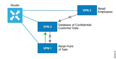
 

Troubleshooting Cisco Catalyst SD-WAN Identity-Based Firewall Policy

User Traffic is Dropped

Problem

User traffic is dropped when it must actually be allowed, based on the policy.

Possible Causes

This issue arises when there are errors while configuring user sessions. Use the show commands to verify the user session configuration both on the Cisco Catalyst SD-WAN Controller and on the Cisco IOS XE Catalyst SD-WAN device. See Monitor Cisco SD-WAN Identity-based Firewall Using the CLI to view the show commands used to the monitor identity-based firewall policy.

Solution

Ensure that the user session information is available on the device for policy enforcement.

Configuration Example for Cisco Catalyst SD-WAN Identity-Based Firewall

The following example shows how to configure connectivity from the Cisco Catalyst SD-WAN Controller to the Cisco ISE:

identity
 pxgrid
  server-address 10.27.216.141
  user-name      vIPtela_Inc_Regression_vsmart1644552134629
  password       $8$TVGurOH2PcGuJQnUUyDku5BkdBae5BpmIyBCqpv555U05MccrXQ97hQkkCaRNh6W
  subscriptions user-identity
  domain-name    SDWAN-IDENTITY.CISCO.COM
  vpn 0
 !
!

The following example shows how to configure a Cisco Catalyst SD-WAN identity-based firewall on a Cisco IOS XE Catalyst SD-WAN device:

class-map type inspect match-any TestID
 match identity source user-group "SDWAN-IDENTITY.CISCO.COM/Users/Domain Users"
class-map type inspect match-all visFW-seq-1-cm_
 match access-group name visFW-seq-Rule_1-acl_
class-map type inspect match-all visFW-seq-11-cm_
 match class-map TestID
 match access-group name visFW-seq-Rule_2-acl_
 
policy-map type inspect visFW
 class type inspect visFW-seq-1-cm_
  inspect
 class type inspect visFW-seq-11-cm_
  inspect
 class class-default
  drop
 
ip access-list extended visFW-seq-Rule_1-acl_
 11 permit object-group visFW-Rule_1-svc_ object-group visFW-Rule_1-nw-src_ any
ip access-list extended visFW-seq-Rule_2-acl_
 11 permit object-group visFW-Rule_2-svc_ any any
 
object-group network visFW-Rule_1-nw-src_
 10.1.1.0 255.255.255.0
object-group service visFW-Rule_1-svc_
 ip
object-group service visFW-Rule_2-svc_
 ip
 11 permit object-group visFW-Rule_1-svc_ object-group visFW-Rule_1-nw-src_ any
 11 permit object-group visFW-Rule_2-svc_ any any
 
 vpn zone security
zone security Zone23
 vpn 2
 vpn 3
zone security zone0
 vpn 0
zone-pair security ZP_Zone23_zone0_visFW source Zone23 destination zone0
 service-policy type inspect visFW