Install the FIPS Opacity Shield
 Note |
Because the FIPS opacity shield covers the serial number on the chassis, the CO should copy the serial number and store it in a secure place. The serial number is needed when you call Cisco TAC. See Serial Number and Digital Documentation Portal QR Code for the location of the serial number. |
Note |
You can only install the FIPS opacity shield with the desktop mount or wall mount. The rack mount does not support the FIPS shield. See Desktop-Mount the Chassis and Wall-Mount the Chassis for more information. |
Before you begin
 Caution |
This procedure should be performed only by the Crypto Officer (CO). |
You need the following to install the FIPS opacity shield:
-
#1 Phillips head screwdriver
-
The following items from the FIPS kit (part number 69-100649-01):
-
One FIPS opacity shield (part number 800-106088-01)
-
Three M3 x 66 mm (part number 48-0384-01) screws used to attach the FIPS opacity shield to the chassis
-
Nine Tamper Evidence Labels (TELs) (part number 47-25553-01)
Note
The TELs are made of a special thin gauge vinyl with self-adhesive backing. Once the CO attaches them on the chassis, any attempt to open the chassis damages the TELs or the chassis cover. Because the TELs have nonrepeated serial numbers, the CO can inspect them for damage and compare them against the applied serial numbers to verify whether the chassis has been tampered with. TELs with curled corners, rips, and slices indicate tampering. The word “FIPS” or “OPEN” may appear if the label has been peeled back.
-
Procedure
|
Step 1 |
Copy the serial number and store in a secure place. |
||||||||||
|
Step 2 |
If the chassis is mounted on a wall, uninstall it by following Steps 9-10 in Wall-Mount the Chassis. |
||||||||||
|
Step 3 |
Install the FIPS cover by holding the chassis right-side up and sliding the chassis into the FIPS cover front panel first. 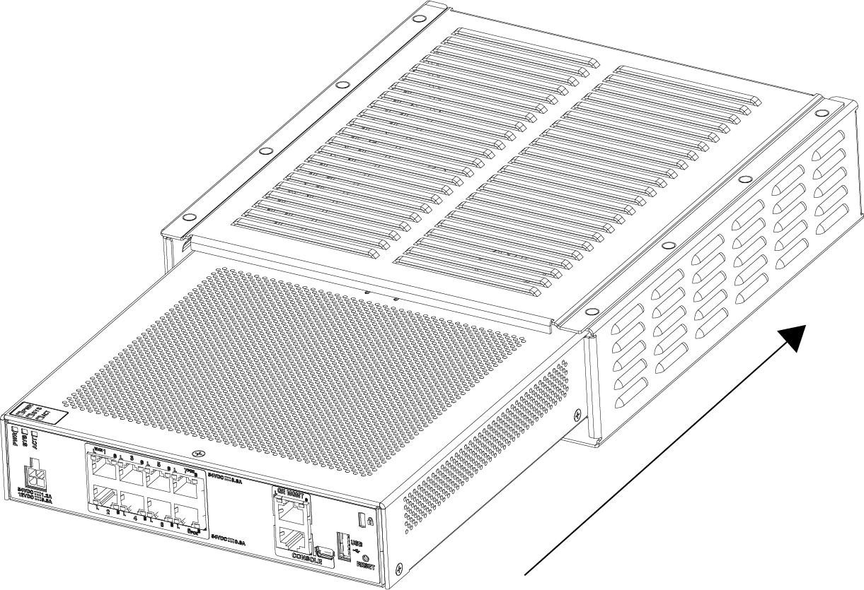
|
||||||||||
|
Step 4 |
Turn the chassis with the FIPS cover installed over and install the three screws. 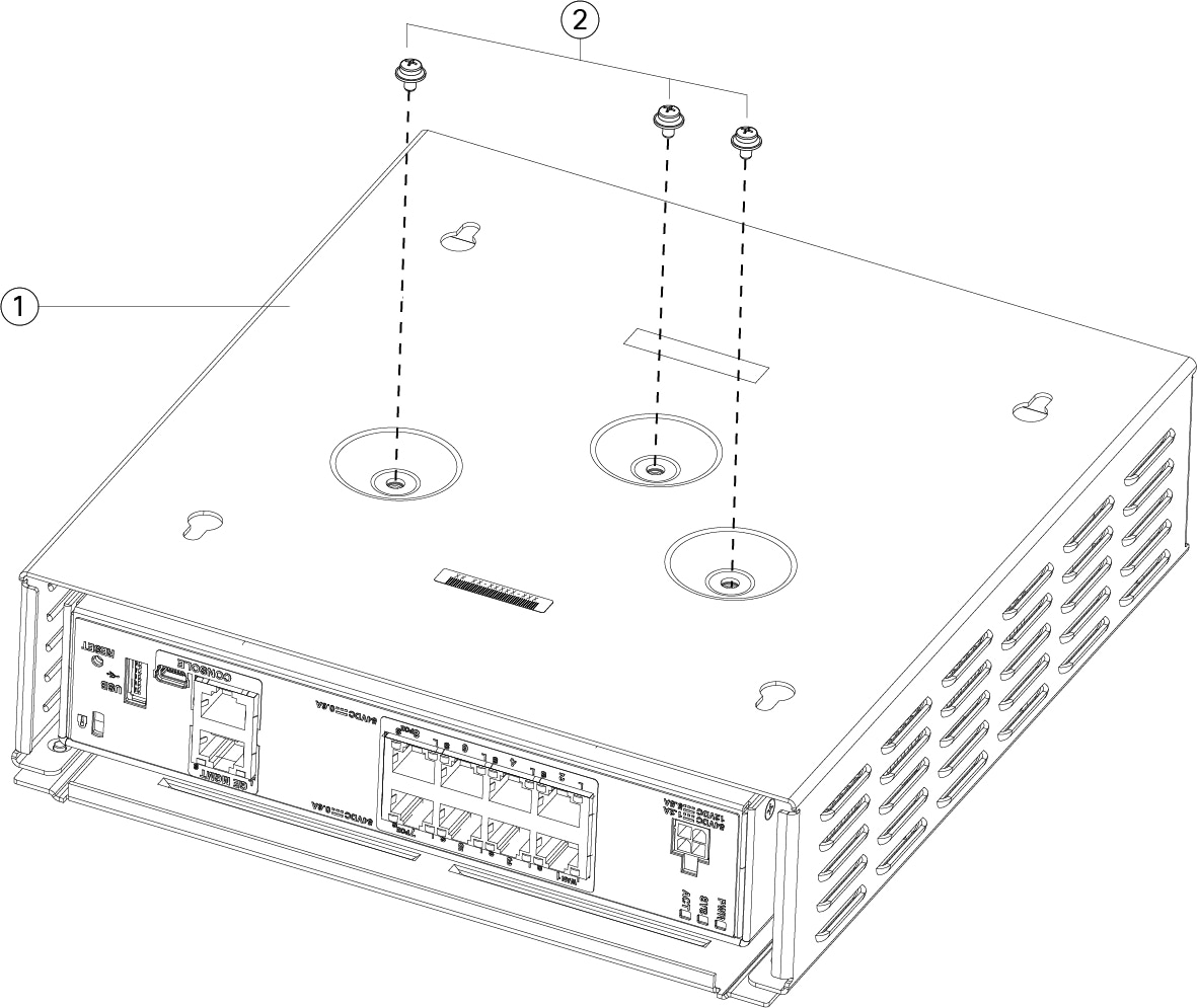
|
||||||||||
|
Step 5 |
Before you attach the TELs, clean the chassis and FIPS cover of any grease, dirt, or oil with alcohol-based cleaning pads. |
||||||||||
|
Step 6 |
Attach four of the TELs, three on the bottom of the chassis over the screws and one on the front of the chassis. See the figure below for the correct placement. The figure shows the bottom of the chassis where you place three of the TELs. Allow the TELs to cure for a minimum of 12 hours.
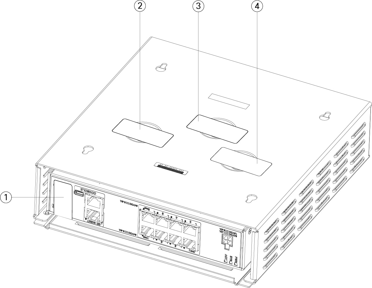
|
||||||||||
|
Step 7 |
Reinstall the chassis in the wall mount if you are using a mount. See Wall-Mount the Chassis for the procedure. |
||||||||||
|
Step 8 |
Attach the power cable to the chassis and connect it to an electrical outlet. |
||||||||||
|
Step 9 |
Press the power switch on the rear panel. |
||||||||||
|
Step 10 |
Check the power LED on the front panel. See Status LEDs for a description of the power LED. Solid green indicates that the chassis is powered on. |
||||||||||
|
Step 11 |
Place the chassis in FIPS mode. See the following procedures for how to place the chassis in FIPS mode:
|
What to do next
See the Cisco Firepower 1010 Getting Started Guide for further configuration information.
 Feedback