Configuring Cisco DNA Service for Bonjour over EVPN VXLAN Layer 3 Overlay Networks

Prerequisites for Cisco DNA Service for Bonjour over EVPN VXLAN Layer 3 Overlay Networks

This section provides the list of prerequisites for a Cisco Catalyst leaf switch that needs to be deployed in SDG Agent mode.:

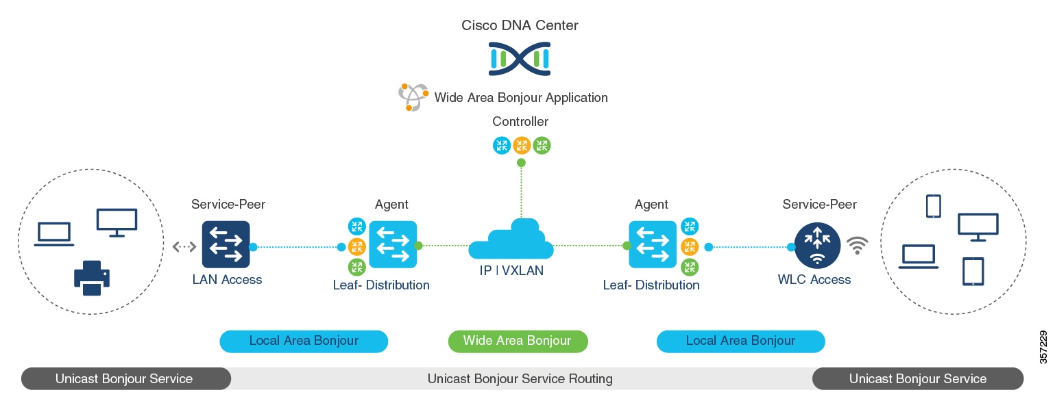
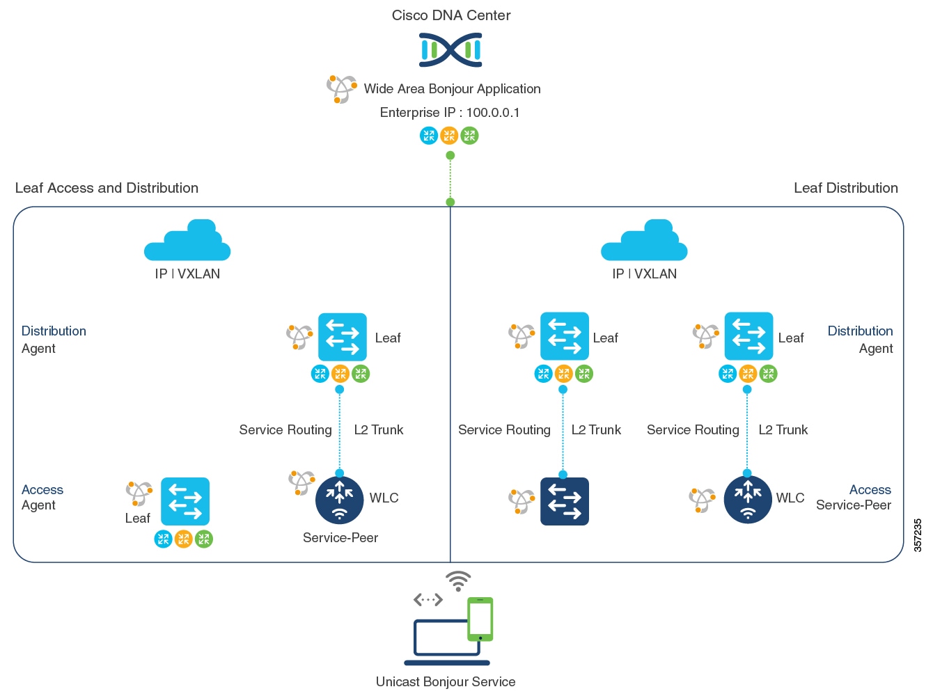
  • Ensure that you successfully configure and operate the BGP EVPN VXLAN overlay networks on the Cisco Catalyst devices before you configure Cisco Local Area and Wide Area Bonjour for LAN and WLAN networks.

  • Verify that the targeted leaf switch is supported in SDG Agent and the Layer 2 access switch is supported in Service-Peer mode. See Supported Platforms for more information.

  • Verify that the targeted SDG Agent leaf switch, Service-Peer switch and Service-Peer wireless controller (WLC) run on the minimum required Cisco IOS XE software version.

  • Ensure that the SDG Agent leaf switch, Service-Peer switch, and Service-Peer WLC run on a valid Cisco DNA Advantage license.

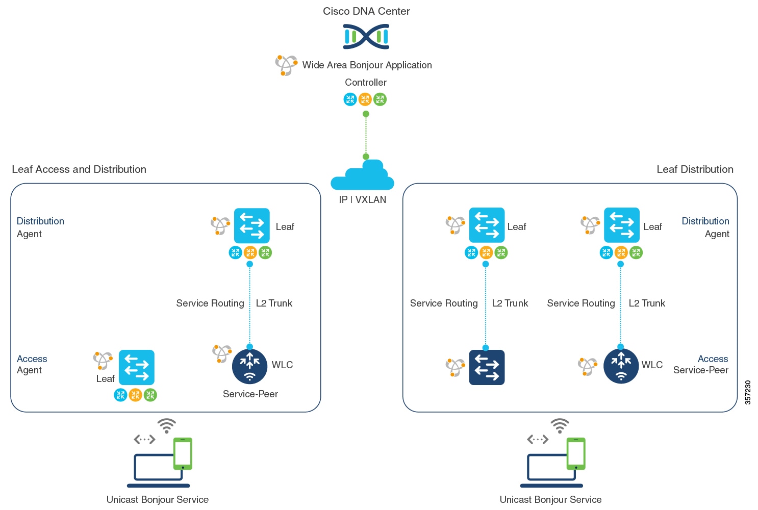
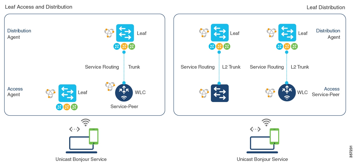
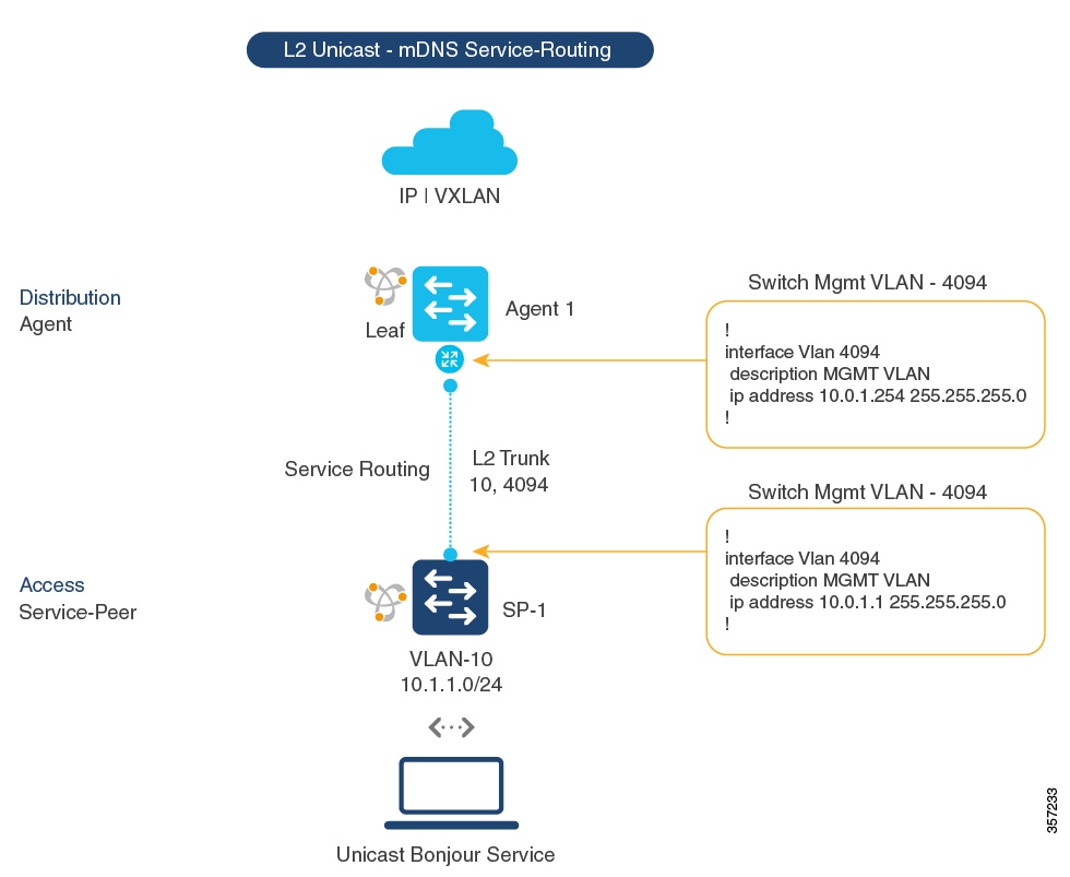
  • In a multilayer network with Layer 2 unicast service-routing between an SDG Agent leaf switch in distribution layer and Service-Peer, ensure that the connection is through a Layer 2 trunk in static mode.

  • Ensure that the Cisco DNA Center has IP connectivity with the SDG Agent leaf switch in either the underlay or overlay network.

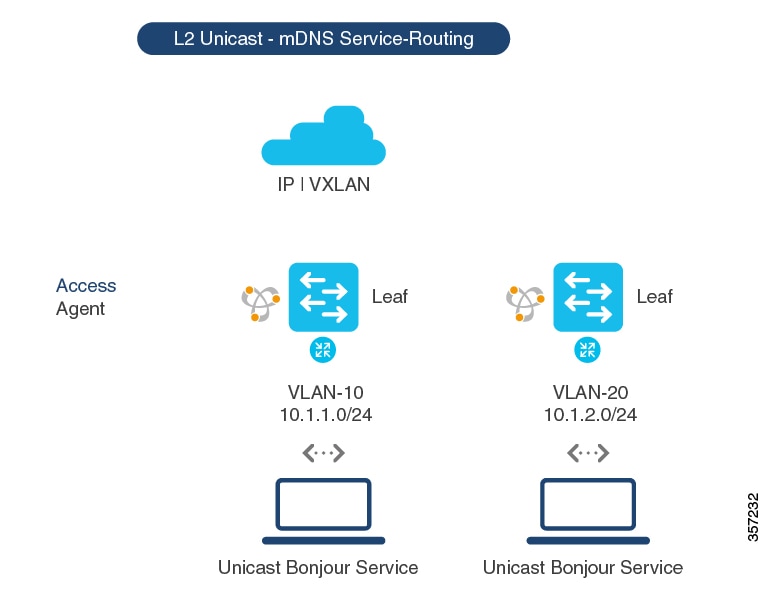
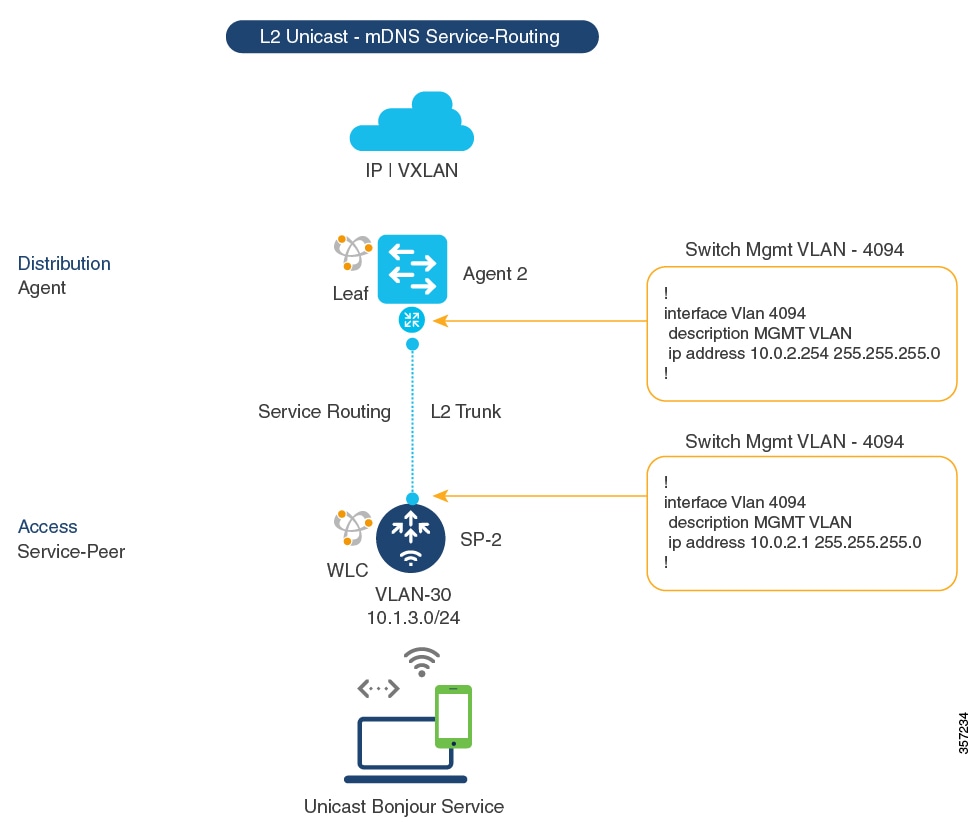
  • Ensure that the SDG Agent leaf switch has IP connectivity with the Service-Peer switch and Service-Peer WLC in the same IPv4 subnet when the traffic is globally routed through the management VLAN.

  • Verify that wireless AP multicast is configured in the underlay network and Cisco Wireless APs have successfully joined the AP multicast group announced by the WLC.


Note


The leaf switch can also enable unicast-based service-routing with a downstream Layer 2 access switch and Catalyst 9800 Series WLC.


Restrictions for Wide Area Bonjour over EVPN VXLAN Layer 3 Overlay Networks

  • Only Cisco Catalyst 9000 Series Layer 2 Ethernet switches that are connected to a distribution layer leaf switch can be deployed in Service-Peer mode. No other classic Cisco Catalyst LAN switches are supported in Service-Peer mode.

  • Cisco Embedded WLC is not supported on Cisco Catalyst Series switches.

  • Multicast DNS (mDNS) Trust port is not supported on the Layer 2 port channel interface of Cisco Catalyst Series switches.

  • Local-area service-routing is not supported on the management port of Cisco Catalyst Series switches.

Information About Cisco DNA Service for Bonjour over EVPN VXLAN Layer 3 Overlay Networks

Cisco Catalyst 9000 Series leaf switches or VTEPs introduce hierarchical service-routing for standard-based BGP EVPN VXLAN overlay networks. Leaf switches can function as Service Discovery Gateway Agents (SDG-Agents) to enable mDNS service-routing for Layer 3 and Layer 2 overlay networks. The enhanced gateway function (at the first hop of wired and wireless networks) communicates with directly associated, industry-standard, RFC 6762-compliant multicast DNS (mDNS) end points in Layer 2 unicast mode. Communication in unicast mode eliminates Layer 2 mDNS traffic flooding and enables service discovery across Layer 3 networks for large scale and enterprise-grade LAN and WLAN overlay networks. By doing this, unicast mode enhances security, bandwidth, scale, and performance for underlay and overlay fabric networks.

The following image illustrates a BGP EVPN VXLAN fabric that supports service-routing for wired and wireless user endpoints over Layer 3 overlay networks:

Figure 1. Cisco Wide Area Bonjour over BGP EVPN VXLAN Layer 3 Overlay Networks

A leaf switch in enterprise campus access or distribution layer can perform Wide Area Bonjour service-routing. Service-routing allows the leaf switch to establish stateful and reliable communication with a centralized Cisco DNA Center in the underlay network. The leaf can also discover and distribute policy-based services. Service data communication between mDNS sources and receivers over an EVPN VXLAN network uses segmented Layer 3 overlay forwarding topologies. A leaf switch can extend unicast-based service-routing through a downstream Layer 2 access device to build a Local Area Bonjour domain for the VXLAN fabric. The domain allows end-to-end, unicast-based service-routing for EVPN VXLAN Layer 3 overlay networks. The downstream Layer 2 access device in the fabric can be one of:

  • A Cisco Catalyst 9000 Series Ethernet switch

  • A Cisco Catalyst 9800 Series WLC

Understanding Wide Area Bonjour over EVPN VXLAN Layer 3 Overlay Networks

A BGP EVPN Layer 3 leaf switch provides an IP gateway to a Layer 3-segmented, VRF-enabled interface to attach wired and wireless endpoints locally. Each BGP EVPN leaf switch in an access or distribution layer network provides a demarcation point to the broadcast boundary of its local Layer 2 network. This demarcation prevents mDNS service discovery and distribution beyond the leaf switch in the access or distribution layer network.

Cisco Wide Area Bonjour for BGP EVPN overlay networks enables unicast-based mDNS service discovery and distribution beyond the boundary of the single IP network. A network-wide distributed BGP EVPN leaf switch in an access or distribution layer network builds stateful and reliable communication with a Cisco DNA Center. This link enables policy- and location-based mDNS service-routing between the leaf switches for Layer 3 overlay networks.

The BGP EVPN fabric boundary can be initiated from the access or distribution layer network depending on network design. The following figure provides two deployment alternatives to determine the handling of mDNS communication with downstream Layer 2 switches or WLCs and upstream fabric networks:

  • Leaf Access and Distribution: The LAN access in Layer 3 mode provides the Layer 2–Layer 3 boundary to enable mDNS service-routing over the EVPN fabric network. The leaf switch in distribution layer can connect to a downstream Layer 2 WLC in Service-Peer mode and enable Unicast-based service-routing.

  • Leaf Distribution: The LAN and Wireless distribution layer provides the Layer 2–Layer 3 boundary to enable mDNS service-routing over the EVPN fabric network. The leaf switch in Distribution layer can connect to a downstream Layer 2 LAN access switch and WLC in Service-Peer mode and enable Unicast-based service-routing.

Figure 2. Wide Area Bonjour for Wired and Wireless BGP EVPN Layer 3 Overlay Networks

mDNS service-routing for EVPN VXLAN Layer 3 overlay networks supports dynamic service discovery from a local network and performs service-routing with a centralized Cisco DNA-Center. The mDNS service-routing functions in the following ways with Bonjour domains:

  • Local Area Bonjour Domain: A BGP EVPN Layer 3 leaf switch discovers and distributes mDNS services dynamically. The leaf switch distributes the mDNS services to directly or indirectly attached wired and wireless endpoints in a Layer 2 network. The leaf switch in distribution layer can establish unicast-based service-routing with a downstream Layer 2 access device to improve scale, performance, and location-based service capabilities. The downstream Layer 2 access device can be either a Cisco Catalyst Series switch or a Cisco 9800 Series WLC.

    SeeConfiguring Local Area Bonjour Unicast Mode for Wired and Wireless Local Mode Networks for detailed configuration steps.

  • Wide Area Bonjour Domain: A BGP EVPN Layer 3 leaf switch and Wide Area Bonjour application in a Cisco DNA Center work together to build secure service-routing and peering. The link-up enables policy-based and location-based mDNS service-routing across Layer 3 overlay networks. The Layer 3 overlay network allows the exchange of VXLAN data only between the leaf switch and the Cisco DNA Center. The endpoints of mDNS service providers and receivers do not forward VXLAN data between themselves.

    See Configuring Wide Area Bonjour for BGP EVPN VXLAN Layer 3 Overlay Network for detailed configuration steps for Cisco Catalyst 9000 Series switches.

    See Cisco Wide Area Bonjour Application on Cisco DNA Center User Configuration Guide, 2.1.2 Release for more information about how to configure Cisco DNA Center.

How to Configure Cisco DNA Service for Bonjour over EVPN VXLAN Layer 3 Overlay Networks

This section shows how to configure Local and Wide Area Bonjour over Layer 3 overlay networks.

Configuring Local Area Bonjour in Unicast Mode over EVPN VXLAN Layer 3 Overlay Networks

Local Area Bonjour enables unicast-based mDNS service-routing function between the service provider and receiver within the local Layer 2 network boundary. The leaf switch can be directly or indirectly attached to one of:

  • Wired endpoint using an intermediate Layer 2 access switch

  • Wireless endpoint using a Cisco Catalyst 9800 Series WLC

Figure 3. Local Area Bonjour Unicast Mode for Wired and Wireless Local Mode Networks

Service-routing for Local Area Bonjour enables unicast-based mDNS service discovery and distribution in the access layer through the BGP EVPN leaf switch. In the distribution layer, service-routing achieves this with multiple downstream Layer 2 Ethernet switches or Cisco WLCs in Service-Peer mode. To configure Local Area Bonjour in unicast mode over an EVPN VXLAN Layer 3 overlay network for the deployment shown above, perform the following operations:

  • (Optional) Configure the Layer 2 access switch in Service-Peer mode to enable the first hop mDNS gateway that directly connects it to mDNS wired and wireless endpoints.

  • (Optional) Configure the Cisco Catalyst 9800 series WLC in Service-Peer mode to enable the first hop mDNS gateway that directly connects it to mDNS wired and wireless endpoints.

  • Configure the Layer 3 BGP EVPN access leaf switch as an SDG agent.

  • Configure the Layer 3 BGP EVPN distribution leaf switch as an SDG agent.


Note


Ensure that you BGP EVPN VXLAN before you enable an mDNS gateway on a VLAN mapped to a Layer 3 overlay network. For detailed information and configuration steps, see BGP EVPN VXLAN Configuration Guide for the applicable release.


Configuring Layer 3 BGP EVPN Access Leaf SDG Agents

This sub-section shows a sample configuration to enable unicast-based service-routing and mDNS gateway functionality on a Layer 3 BGP EVPN access leaf swtich for the topology in the figure below:

Figure 4. Layer 3 BGP EVPN Leaf Access SDG Agents
Table 1. Configuring Layer 3 BGP EVPN Access Leaf SDG Agents

Configuration Step

Layer 3 Access Leaf SDG Agent in VLAN 10

Layer 3 Access Leaf SDG Agent in VLAN 20

Enable mDNS gateway and set the gateway mode on the Layer 3 Access switch.

!
mdns-sd gateway
 mode sdg-agent
!
mdns-sd gateway
 mode sdg-agent
!

Create a unique mDNS inbound policy to permit ingress AirPrint service announcement from the service provider.

!
mdns-sd service-list LOCAL-AREA-SERVICES-IN in
 match printer-ipp
!
!
mdns-sd service-list LOCAL-AREA-SERVICES-IN in
 match printer-ipp
!

Create a unique mDNS outbound policy to permit egress AirPrint service response to the service receiver.

Associate location-filter to share AirPrint service information from the grouped VLAN

!
mdns-sd service-list LOCAL-AREA-SERVICES-OUT out
 match printer-ipp
!
!
mdns-sd service-list LOCAL-AREA-SERVICES-OUT out
 match printer-ipp
!

Associate the inbound and outbound service lists to a unique service-policy.

!
mdns-sd service-policy LOCAL-AREA-POLICY
 service-list LOCAL-AREA-SERVICES-IN
 service-list LOCAL-AREA-SERVICES-OUT
!
!
mdns-sd service-policy LOCAL-AREA-POLICY
 service-list LOCAL-AREA-SERVICES-IN
 service-list LOCAL-AREA-SERVICES-OUT
!

Enable unicast-based mDNS gateway for wired users in VLAN 10 and VLAN 20 that are mapped to the Layer 3 VRF for BGP EVPN VXLAN.

Configure the service-policy with advanced parameters and associate it with the VLAN.

!
! mDNS Unicast based gateway
!
vlan configuration 10
 mdns-sd gateway
   service-policy LOCAL-AREA-POLICY
   active-query timer 3600
!
!
! mDNS Unicast based gateway
!
vlan configuration 20
 mdns-sd gateway
   service-policy LOCAL-AREA-POLICY
   active-query timer 3600
!

Configure the wired users for VLAN 10 and VLAN 20 with IP address, Layer 3 VRF, and any other required parameters.

!
interface Vlan 10
 description BLUE VRF WIRED USER VLAN
 vrf forwarding BLUE_VRF
 ip address 10.1.1.254 255.255.255.0
 no shutdown
!
!
interface Vlan 20
 description BLUE VRF WIRED USER VLAN
 vrf forwarding BLUE_VRF
 ip address 10.1.2.254 255.255.255.0
 no shutdown
!

Configuring the BGP EVPN Leaf Switch and the Layer 2 Access Switch for Service-Routing

This sub-section shows a sample configuration to enable unicast-based service-routing between a Layer 2 access switch and a BGP EVPN VXLAN distribution leaf switch for the topology in the figure below:

Figure 5. Layer 2 Access Switch Service-Peer and Distribution Leaf Switch SDG Agent
Table 2. Configuring the BGP EVPN Leaf Switch and the Layer 2 Access Switch for Service-Routing

Configuration Step

Layer 2 Access Switch as Service Peer

Distribution Leaf as SDG Agent

Step 1: Enable mDNS gateway and the gateway modes on the access switch (SP-1) and distribution switch (Agent-1).

!
mdns-sd gateway
 mode service-peer
!
!
mdns-sd gateway
 mode sdg-agent
!

Create a unique mDNS inbound policy to permit ingress AirPrint service announcement from the service provider on the access switch (SP-1) .

!
mdns-sd service-list LOCAL-AREA-SERVICES-IN in
 match printer-ipp
!
!

Step 3: Create a unique mDNS outbound policy to permit egress AirPrint service response to the locally attached wired service receiver.

!
mdns-sd service-list LOCAL-AREA-SERVICES-OUT out
 match printer-ipp
!
!

Step 4: Associate the inbound and outbound service lists to a unique service-policy.

!
mdns-sd service-policy LOCAL-AREA-POLICY
 service-list LOCAL-AREA-SERVICES-IN
 service-list LOCAL-AREA-SERVICES-OUT
!
!

Step 5: Enable unicast-based mDNS gateway on wired users in VLAN 10 mapped to the Layer 3 VRF for BGP EVPN VXLAN.

Associate the service-policy with advanced parameters.

On the Service-Peer, configure the network IP address for the SDG-Agent's management VLAN and the parameters for the local source management VLAN to enable unicast service-routing over Layer 2 trunk interface.

!
! mDNS Unicast based gateway
!
vlan configuration 10
 mdns-sd gateway
   service-policy LOCAL-AREA-POLICY
   active-query timer 3600
   sdg-agent 10.0.1.254
   source-interface Vlan 4094
!
!
! mDNS Unicast based gateway
!
vlan configuration 10
 mdns-sd gateway
!

Step 6: Configure the wired user in VLAN 10 with the IP address, Layer 3 VRF, and any other parameters, as required.

!
!
interface Vlan 10
 description BLUE VRF WIRED USER VLAN
 vrf forwarding BLUE_VRF
 ip address 10.1.1.254 255.255.255.0
 no shutdown
!

Configuring the Layer 2 Cisco WLC and the BGP EVPN Leaf Switch for Service-Routing

This sub-section shows a sample configuration to enable unicast-based service-routing between a Cisco Catalyst 9800 WLC and a BGP EVPN VXLAN distribution leaf switch for the topology in the figure below:

Figure 6. Catalyst 9800 WLC Service-Peer and Distribution Leaf Switch SDG Agent
Table 3. Configuring the Layer 2 Cisco WLC and the BGP EVPN Leaf Switch for Service-Routing

Configuration Step

WLC Service-Peer

Layer 3 Distribution Leaf Switch SDG Agent

Step 1: Enable mDNS gateway and set the gateway mode.

  • WLC Service Peer: Service Peer mode is the default mode with mDNS gateway configuration.

  • Layer 3 Distribution Leaf Switch: SDG Agent mode is the default mode with mDNS gateway configuration.

!
mdns-sd gateway
!
!
mdns-sd gateway
 mode sdg-agent
!

Step 2: Create a unique mDNS inbound policy to permit ingress AirPrint service announcement on the WLC in Service-Peer mode.

!
mdns-sd service-list LOCAL-AREA-SERVICES-IN in
 match printer-ipp
!
!

Step 3: Create a unique mDNS outbound policy to permit egress AirPrint service response on the WLC in Service-Peer mode.

!
mdns-sd service-list LOCAL-AREA-SERVICES-OUT out
 match printer-ipp
!
!

Step 4: Associate the inbound and outbound service lists to a unique service-policy.

!
mdns-sd service-policy LOCAL-AREA-POLICY
 service-list LOCAL-AREA-SERVICES-IN
 service-list LOCAL-AREA-SERVICES-OUT
!
!

Step 5: Activate unicast mDNS gateway and attach the service-policy on the WLAN and the wired VLAN.

  • WLC: Activate mDNS gateway for each WLAN Policy Profile and SSID.

  • Switch: Activate mDNS gateway for each VLAN.

!
wireless profile policy WLAN-PROFILE
 shutdown
 mdns-sd service-policy LOCAL-AREA-POLICY
 no shutdown
!
wlan WLAN-PROFILE 1 blizzard
 shutdown
 mdns-sd-interface gateway
 no shutdown
!
!
! mDNS Unicast based gateway
!
vlan configuration 30
 mdns-sd gateway
!

Step 6: (Optional) Enable service-routing on the wired Service-Peer mDNS between the local VLANs. Enable location-based wireless service on the WLC.

!
mdns-sd service-policy LOCAL-AREA-POLICY
 location ap-location
!
!

Step 7: Enable unicast service-routing between the wired and wireless Service-Peer and SDG Agent.

Configure the SDG Agent's IP address and the wireless management source VLAN's ID and IP address on the WLC.

!
mdns-sd gateway
  source-interface vlan 4094
  sdg-agent 10.0.2.254
!
!

Step 8: Configure the wireless user VLAN with the IP address, Layer 3 VRF, and any other parameters, as required.

!
!
interface Vlan 30
 description BLUE VRF WIRELESS USER VLAN
 vrf forwarding BLUE_VRF
 ip address 10.1.3.254 255.255.255.0
 no shutdown
!

Configuring Wide Area Bonjour over EVPN VXLAN Layer 3 Overlay Networks

To configure Wide Area Bonjour and connect with wired or wireless endpoints across the IP network boundary, enable unicast-mode service-routing on:

  • the Layer 3 access leaf switch SDG agent

  • the WLC distribution leaf switch SDG agent

Once you configure both SDG agents, you enable service-routing peering with Cisco DNA Center Wide Area Bonjour application that supports BGP EVPN VXLAN. Once you enable service-routing, global discovery and distribution is enabled and the Layer 3 leaf switch communicates with Cisco DNA Center to perform service-discovery beyond its boundary. mDNS services can be discovered and distributed among the endpoints in the same or in different Layer 3 overlay networks.

For detailed steps about how to configure Wide Area Bonjour service-routing and service policies on a Cisco DNA Center, see Wide Area Bonjour Configuration Guidelines in Cisco Wide Area Bonjour Application on Cisco DNA Center User Configuration Guide, 2.1.2 Release.


Note


We recommend that you use the Loopback interface to establish service-routing between the leaf switches and Cisco DNA Center in the underlay network.


Figure 7. Deployment Model for Wide Area Bonjour over BGP EVPN VXLAN
Deployment Model for Wide Area Bonjour over BGP EVPN VXLAN

The following table shows how to enable unicast-based service-routing on Layer 3 overlay networks connected to wired endpoints or wireless endpoints across IP network boundary:


Note


In Cisco IOS XE 17.6.2 and later releases, you can configure a customized controller service policy.


Cisco IOS XE 17.6.1 and Earlier Releases

Table 4. Configuring SDG Agents to Configure Wide Area Bonjour over EVPN VXLAN Layer 3 Overlay Networks

Configuration Step

Layer 3 Access Leaf SDG Agent

WLC Distribution Leaf SDG Agent

Step 1: Enable mDNS gateway and set the gateway mode.

!
mdns-sd gateway
!
!
mdns-sd gateway
!

Step 2: Activate the unicast mDNS gateway on the wired VLAN and Wireless user VLAN on the respective SDG Agents.

!
vlan configuration 10
 
mdns-sd gateway
!
!
vlan configuration 30
 
mdns-sd gateway
!

Step 3: Create unique controller-bound mDNS policy to permit egress AirPrint service discovery and distribution from the Catalyst Switch in SDG Agent mode.

Inbound policy towards the controller is not required.

!
mdns-sd service-list 
WIDE-AREA-SERVICES-OUT out
 
match printer-ipp
!
!
mdns-sd service-list 
WIDE-AREA-SERVICES-OUT out
 
match printer-ipp
!

Step 4: Associate the outbound service-list to a unique service-policy.

!
mdns-sd service-policy WIDE-AREA-POLICY
  
 service-list WIDE-AREA-SERVICES-OUT
!
!
mdns-sd service-policy WIDE-AREA-POLICY
 
 service-list WIDE-AREA-SERVICES-OUT
!

Step 5: Enable Wide Area Bonjour service-routing. Configure the service export with the associated controller parameters like IP Address, source interface for stateful connection, and mandatory egress policy for Wide Area service-routing.

!
service-export mdns-sd controller 
DNAC-CONTROLLER-POLICY
 
  controller-address 100.0.0.1
 
  controller-source-interface LOOPBACK 0
 
  controller-service-policy WIDE-AREA-POLICY
!
!
service-export mdns-sd controller 
DNAC-CONTROLLER-POLICY
 
  controller-address 100.0.0.1
     
  controller-source-interface LOOPBACK 0
 
  controller-service-policy WIDE-AREA-POLICY
!

Cisco IOS XE 17.6.2 and Later Releases

Table 5. Configuring SDG Agents to Configure Wide Area Bonjour over EVPN VXLAN Layer 3 Overlay Networks

Configuration Step

Layer 3 Access Leaf SDG Agent

WLC Distribution Leaf SDG Agent

Step 1: Enable mDNS gateway and set the gateway mode.

!
mdns-sd gateway
!
!
mdns-sd gateway
!

Step 2: Activate the unicast mDNS gateway on the wired VLAN and Wireless user VLAN on the respective SDG Agents.

!
vlan configuration 10
 
 mdns-sd gateway
!
!
vlan configuration 30
 
 mdns-sd gateway
!

Step 3: Enable Wide Area Bonjour service-routing. Configure the service export with the associated controller parameters like IP Address and source interface for stateful connection for Wide Area service-routing. Inbound policy towards the controller is not required.

!
service-export mdns-sd
controller
DNAC-CONTROLLER-POLICY

 controller-address 100.0.0.1
 
 controller-source-interface
LOOPBACK 0
!
!
service-export mdns-sd
controller
DNAC-CONTROLLER-POLICY

 controller-address 100.0.0.1

 controller-source-interface
LOOPBACK 0
!

Step 4: (Optional) Create a custom controller service list to permit egress AirPrint service discovery and distribution from the Catalyst Switch in SDG Agent mode.

!
mdns-sd controller
service-list WIDEAREA-SERVICES

match printer-ipp
!
!
mdns-sd controller
service-list WIDEAREA-SERVICES

match printer-ipp
!

Step 5: (Optional) Associate the controller service list to a custom controller service policy.

!
mdns-sd controller service-policy
WIDE-AREA-POLICY

service-list
WIDE-AREA-SERVICES
!
!
mdns-sd controller service-policy
WIDE-AREA-POLICY

service-list
WIDE-AREA-SERVICES
!

Step 6: (Optional) Associate the custom controller service policy to Wide Area Service routing.

Note


A default controller service policy is configured if you do not create a custom controller service policy.

!
service-export mdns-sd controller
DNAC-CONTROLLER-POLICY

controller-service-policy
WIDE-AREA-POLICY
!
!
service-export mdns-sd controller
DNAC-CONTROLLER-POLICY

controller-service-policy
WIDE-AREA-POLICY
!

Verifying Cisco DNA Service for Bonjour over EVPN VXLAN Layer 3 Overlay Networks

This section shows how to verify Cisco DNA Service for Bonjour over EVPN VXLAN Layer 3 overlay networks.

Verifying Local Area Bonjour over an EVPN VXLAN Layer 3 Overlay Network

This section shows how to verify Local Area Bonjour over EVPN VXLAN Layer 3 overlay networks. The examples in this section show the mDNS configuration, service discovery status, and service distribution status for the policies applied on devices in Service-Peer and SDG Agent modes.

Verifying Wired Service-Peer Configuration

The examples in this section show how to verify the wired Service-Peer configuration on the Cisco Catalyst Series switch (SP-1) in Service-Peer mode. You can determine the operational status once you configure and discover AirPrint service from the local network.

This example shows a sample output for the show mdns-sd summary vlan vlan-id command on SP-1:

SP-1# show mdns-sd summary vlan 10
VLAN  :  10
==========================================					
mDNS Gateway		:	Enabled
mDNS Service Policy	:	LOCAL-AREA-POLICY
Active Query		:	Enabled
Periodicity               :	 3600 Seconds
Transport Type	     :	IPv4
Service Instance Suffix   :	Not-Configured
mDNS Query Type	    :	ALL
SDG Agent IP              :	10.0.1.254
Source Interface          :	Vlan4094

SP-1# 

This example shows a sample output for the show mdns-sd service-policy name policy-name command on SP-1:

SP-1# show mdns-sd service-policy name LOCAL-AREA-POLICY
Service Policy Name		Service List IN Name		Service List Out Name
===============================================================================
LOCAL-AREA-POLICY                    LOCAL-AREA-SERVICES-IN	LOCAL-AREA-SERVICES-OUT

SP-1# 

This example shows a sample output for the show mdns-sd cache vlan vlan-id command on SP-1:

SP-1# show mdns-sd cache vlan 10
NAME                                  TYPE        TTL/Remaining    Vlan-Id/If-name        Mac Address        RR Record Data
_universal._sub._ipp._tcp.local        PTR        4500/4486        Vl10                ac18.2651.03fe    Bldg-1-FL1-PRN._ipp._tcp.local
_ipp._tcp.local                        PTR        4500/4486        Vl10                ac18.2651.03fe    Bldg-1-FL1-PRN._ipp._tcp.local
Bldg-1-FL1-PRN._ipp._tcp.local         SRV        4500/4486        Vl10                ac18.2651.03fe    0    0    631    Bldg-1-FL1-PRN.local
Bldg-1-FL1-PRN.local                    A         4500/4486        Vl10                ac18.2651.03fe    10.1.1.1
Bldg-1-FL1-PRN.local                  AAAA        4500/4486        Vl10                ac18.2651.03fe    2001:10:153:1:79:A40C:6BEE:AEEC
Bldg-1-FL1-PRN._ipp._tcp.local         TXT        4500/4486        Vl10                ac18.2651.03fe    (451)'txtvers=1''priority=30''ty=EPSON WF-3620 Series''usb_MFG=EPSON''usb_MDL=W~'~

SP-1# 

This example shows a sample output for the show mdns-sd statistics vlan vlan-id command on SP-1:

SP-1# show mdns-sd statistics vlan 10
mDNS Statistics

 Vl10:
  mDNS packets sent		: 612
     IPv4 sent		: 612
       IPv4 advertisements sent 	: 0
       IPv4 queries sent		: 612
     IPv6 sent		: 0
       IPv6 advertisements sent	: 0
       IPv6 queries sent		: 0
  Unicast sent		: 0
  mDNS packets rate limited	: 0
  mDNS packets received	: 42
   advertisements received	: 28
   queries received		: 14
     IPv4 received		: 42
       IPv4 advertisements received	: 28
       IPv4 queries received	: 14
     IPv6 received		: 0
       IPv6 advertisements received	: 0
       IPv6 queries received	: 0
  mDNS packets dropped	: 0
  =========================================
  Query Type                        	: Count
  =========================================
  PTR                               	: 12
  SRV                               	: 0
  A                                 	: 0
  AAAA                              	: 0
  TXT                               	: 0
  ANY                               	: 3
  =================================================
  PTR Name                             Advertisement     Query
  =================================================
_ipp._tcp.local                              9         	4

SP-1# 

Verifying Wired SDG Agent Configuration and Service-Routing Status

The examples in this section show how to verify the mDNS configuration and service-routing on Wired SDG Agent (SDG-1). SDG-1 is locally connected to a Layer 2 access switch (SP-1) in Service-Peer mode and centrally paired with a Cisco DNA Center for Wide Area Bonjour service-routing.

This example shows a sample output for the show mdns-sd summary vlan vlan-id command on SDG-1:

SP-1# show mdns-sd summary vlan 10
VLAN  :  10
==========================================
mDNS Gateway        	: Enabled
mDNS Service Policy 	: LOCAL-AREA-POLICY
Active Query        	: Disabled
Transport Type      	: IPv4
Service Instance Suffix	: Not-Configured
mDNS Query Type  	: ALL
SDG Agent IP      	: Not-Configured
Source Interface   	: Not-Configured 

SDG-1# 

This example shows a sample output for the show mdns-sd cache vlan vlan-id command on SDG-1:

SP-1# show mdns-sd cache vlan 10

NAME                                  TYPE        TTL/Remaining    Vlan-Id/If-name            Mac Address        RR Record Data
_universal._sub._ipp._tcp.local        PTR        4500/4500            Vl10                ac18.2651.03fe        Bldg-1-FL1-PRN._ipp._tcp.local
_ipp._tcp.local                        PTR        4500/4500            Vl10                ac18.2651.03fe        Bldg-1-FL1-PRN._ipp._tcp.local
Bldg-1-FL1-PRN._ipp._tcp.local         SRV        4500/4500            Vl10                ac18.2651.03fe        0    0    631    Bldg-1-FL1-PRN.local
Bldg-1-FL1-PRN.local                     A        4500/4500            Vl10                ac18.2651.03fe        10.1.1.1
Bldg-1-FL1-PRN.local                  AAAA        4500/4500            Vl10                ac18.2651.03fe        2001:10:153:1:79:A40C:6BEE:AEEC
Bldg-1-FL1-PRN._ipp._tcp.local         TXT        4500/4500            Vl10                ac18.2651.03fe        (451)'txtvers=1''priority=30''ty=EPSON WF-3620 Series''usb_MFG=EPSON''usb_MDL=W~'~

SDG-1# 

This example shows a sample output for the show mdns-sd sp-sdg statistics command on SDG-1:

SP-1# show mdns-sd sp-sdg statistics
                             One min, 5 mins, 1 hour
Average Input rate (pps)     :      0,        0,          0
Average Output rate (pps)    :      0,        0,          0
 Messages received:
  Query                      : 15796
  ANY query                  : 0
  Advertisements             : 28
  Advertisement Withdraw     : 0
  Interface down             : 0
  Vlan down                  : 0
  Service-peer ID change     : 0
  Service-peer cache clear   : 12
  Resync response            : 6
 Messages sent:
  Query response             : 5975
  ANY Query response         : 0
  Cache-sync                 : 61
  Get service-instance       : 0

SDG-1# 

This example shows a sample output for the show mdns-sd controller detail command on SDG-1:

SP-1# show mdns-sd controller detail

Controller : DNAC-Policy
 IP : 100.0.0.1, Dest Port : 9991, Src Port : 42446, State : UP
 Source Interface : Loopback0, MD5 Disabled
 Hello Timer 30 sec, Dead Timer 120 sec, Next Hello 00:00:24
 Uptime 2d05h (17:02:37 UTC Jan 15 2021)
 Service Buffer : Enabled

Service Announcement :
 Filter : DNAC-CONTROLLER-POLICY
 Count 50, Delay Timer 30 sec, Pending Announcement 0, Pending Withdraw 0
 Total Export Count 56, Next Export in 00:00:24

Service Query :
 Query Suppression Enabled
 Query Count 50, Query Delay Timer 15 sec, Pending 0
 Total Query Count 15791, Next Query in 00:00:09

SDG-1# 

Verifying Wireless Service-Peer and Service Routing Status

The examples in this section show how to verify the wireless Service-Peer configuration on the Cisco Catalyst 9800 WLC (SP-2) in Service-Peer mode. You can determine the operational status once you configure and discover AirPrint service from the remote network.

This example shows a sample output for the show mdns-sd summary command on SP-2:

SP-2# show mdns-sd summary
mDNS Gateway: Enabled
Mode: Service Peer
Service Announcement Periodicity(in seconds): 30
Service Announcement Count: 50
Service Query Periodicity(in seconds): 15
Service Query Count: 50
Active Response Timer (in seconds): Disabled
ANY Query Forward: Disabled
SDG Agent IP: 10.0.2.254
Source Interface: Vlan4094
Active Query Periodicity (in minutes): 15
Transport Type: IPv4
mDNS AP service policy: default-mdns-service-policy

SP-2# 

This example shows a sample output for the show wireless profile policy detailed wireless-profile-name command on SP-2:

SP-2# show wireless profile policy detailed WLAN-PROFILE | sec mDNS

mDNS Gateway
  mDNS Service Policy name          : LOCAL-AREA-POLICY

SP-2# 

This example shows a sample output for the show mdns-sd statistics wlan-id wlan-id-value command on SP-2:

SP-2# show mdns-sd statistics wlan-id 1
mDNS Packet Statistics
-------------------------------------------------
mDNS stats last reset time: 01/10/21 21:38:19
mDNS packets sent: 4592
  IPv4 sent: 4592
    IPv4 advertisements sent: 4592
    IPv4 queries sent: 0
  IPv6 sent: 0
    IPv6 advertisements sent: 0
    IPv6 queries sent: 0
  Multicast sent: 0
    IPv4 sent: 0
    IPv6 sent: 0
mDNS packets received: 297
  advertisements received: 80
  queries received: 217
  IPv4 received: 297
    IPv4 advertisements received: 80
    IPv4 queries received: 217
  IPv6 received: 0
    IPv6 advertisements received: 0
    IPv6 queries received: 0
mDNS packets dropped: 297
Query Type Statistics
  PTR queries received: 1720
  SRV queries received: 8
  A queries received: 8
  AAAA queries received: 8
  TXT queries received: 97
  ANY queries received: 153
  OTHER queries received: 0

SP-2# 

This example shows a sample output for the show mdns-sd sp-sdg statistics command on SP-2:

SP-2# show mdns-sd sp-sdg statistics
mDNS SP Statistics
last reset time: 01/10/21 21:37:36

  Messages sent:
   Query                      		: 12675
   ANY query                  	: 0
   Advertisements             	: 24
   Advertisement Withdraw	: 0
   Service-peer ID change   	: 0
   Service-peer cache clear 	: 7
   Resync response           	: 5
  Messages received:
   Query response             	: 4619
   ANY Query response      	: 0
   Cache-sync                 	: 48
   Get service-instance       	: 0

SP-2# 

This example shows a sample output for the show mdns-sd query-db command on SP-2:

SP-2# show mdns-sd query-db
MDNS QUERY DB

Client MAC: 4c32.7593.e3af
  Vlan ID: 30
  Wlan ID: 1
  Location Group ID: 0
    PTR Name(s):
    _ipp._tcp.local

SP-2# 

Verifying Wide Area Bonjour over EVPN VXLAN Layer 3 Overlay Networks

This section shows how to verify Wide Area Bonjour over EVPN VXLAN Layer 3 overlay networks.

The examples in this section show the mDNS configuration and service-routing on a wireless SDG-Agent (SDG-2). SDG-2 is locally connected to a Catalyst 9800 series WLC (SP-2) in Service-Peer mode and centrally paired with a Cisco DNA Center for Wide Area Bonjour service-routing.

This example shows a sample output for the show mdns-sd summary vlan vlan-id command on SDG-2.

SDG-2# show mdns-sd summary vlan 30
VLAN  :  30
==========================================
mDNS Gateway        	: Enabled
mDNS Service Policy 	: LOCAL-AREA-POLICY
Active Query        	: Disabled
Transport Type      	: IPv4
Service Instance Suffix	: Not-Configured
mDNS Query Type  	: ALL
SDG Agent IP      	: Not-Configured
Source Interface   	: Not-Configured 

SDG-2# 

This example shows a sample output for the show mdns-sd sp-sdg statistics command on SDG-2.

SDG-2# show mdns-sd sp-sdg statistics
                             One min, 5 mins, 1 hour
Average Input rate (pps)	:      	0,        0,          0
Average Output rate (pps)	:      	0,        0,          0
 Messages received:
  Query                      		: 12191
  ANY query                  		: 0
  Advertisements             	: 0
  Advertisement Withdraw   	: 0
  Interface down             	: 0
  Vlan down                  		: 0
  Service-peer ID change    	: 0
  Service-peer cache clear 	: 18
  Resync response            	: 10
 Messages sent:
  Query response             	: 1975
  ANY Query response      	: 0
  Cache-sync                 	: 19
  Get service-instance       	: 0

SDG-2# 

This example shows a sample output for the show mdns-sd controller detail command on SDG-2.

SDG-2# show mdns-sd controller detail
 Controller : DNAC-Policy
 IP : 100.0.0.1, Dest Port : 9991, Src Port : 42931, State : UP
 Source Interface : Loopback0, MD5 Disabled
 Hello Timer 30 sec, Dead Timer 120 sec, Next Hello 00:00:19
 Uptime 2d05h (17:10:18 UTC Jan 15 2021)
 Service Buffer : Enabled

Service Announcement :
 Filter : DNAC-CONTROLLER-POLICY
 Count 50, Delay Timer 30 sec, Pending Announcement 0, Pending Withdraw 0
 Total Export Count 0, Next Export in 00:00:19

Service Query :
 Query Suppression Enabled
 Query Count 50, Query Delay Timer 15 sec, Pending 0
 Total Query Count 17093, Next Query in 00:00:19

SDG-2# 

Verifying Cisco DNA Center Configuration and Service-Routing Status

The Cisco Wide Area Bonjour application supports multilevel assurance capabilities for day-to-day operations. The service routing, instance monitoring, management, and troubleshooting in the Cisco Wide Area Bonjour application are divided into three major categories. Each category serves a unique function to manage and troubleshoot Wide Area Bonjour service routing for day-2 operation. The Monitor function comprises the following categories:

  • Dashboard: The landing page of Cisco Wide Area Bonjour application provides an overview of key statistics in multiple formats. It allows you to quickly determine the service-routing health across the network. The network administrator can monitor the operational status of service-routing using:

  • Sub-Domain 360°: Network administrators can collect statistics and status counts in the 360° view. The left-panel monitoring and configuration bar opens automatically upon clicking a subdomain. You can verify configured policies and discovered service instances on a per-subdomain basis of the Configuration section.

  • Monitor: A comprehensive three-tier monitoring and troubleshooting function of the Cisco Wide Area Bonjour application for various day-2 operations. Network administrators use the detail view of the SDG Agent, service instance, and advanced troubleshooting capabilities to manage and troubleshoot the Wide Area Bonjour domain with a single pane of glass in Cisco DNA Center.

For detailed information about assurance capabilities and monitoring of operation details, see Monitor the Cisco Wide Area Bonjour Application module of Cisco Wide Area Bonjour on Cisco DNA Center User Guide, Release 2.1.2.

Additional References for Cisco DNA Service for Bonjour over EVPN VXLAN Layer 3 Overlay Networks

Table 6. Additional References for Cisco DNA Service for Bonjour over EVPN VXLAN Layer 3 Overlay Networks

Related Topic

Document Title

DNA Service for Bonjour Deployment on Cisco Catalyst 9500 Series Switches

Cisco DNA Service for Bonjour Configuration Guide (Catalyst 9500 Switches)

DNA Service for Bonjour Deployment on Cisco Catalyst 9800 Wireless LAN Controllers

Cisco Catalyst 9800 Series Wireless Controller Software Configuration Guide

Cisco Wide Area Bonjour Application on Cisco DNA Center User Guide

Cisco Wide Area Bonjour Application on Cisco DNA Center User Guide, Release 2.1.2