The documentation set for this product strives to use bias-free language. For the purposes of this documentation set, bias-free is defined as language that does not imply discrimination based on age, disability, gender, racial identity, ethnic identity, sexual orientation, socioeconomic status, and intersectionality. Exceptions may be present in the documentation due to language that is hardcoded in the user interfaces of the product software, language used based on RFP documentation, or language that is used by a referenced third-party product. Learn more about how Cisco is using Inclusive Language.
External connectivity with VPLS networks is supported only when bridging is the mode of interworking between the two domains.
Integrated routing and bridging (IRB) is not supported between a BGP EVPN VXLAN fabric and a VPLS network.
External Connectivity with Layer 3 networks is supported only for IPv4 and IPv6 unicast traffic.
External connectivity with an MVPN network is not supported for multicast traffic.
Import of EVPN IP routes, which includes both route type 5 and route type 2 host routes, to global routing table is not supported.
Information About EVPN VXLAN External Connectivity
External connectivity allows the movement of Layer 2 and Layer 3 traffic between an EVPN VXLAN network and an external network.
It also enables the EVPN VXLAN network to exchange routes with the externally connected network. Routes within an EVPN VXLAN
network are already shared between all the VTEPs or leaf switches. External connectivity uses the VTEPs on the periphery of
the network to pass on these routes to an external Layer 2 or Layer 3 network. Similarly, the EVPN VXLAN network imports the
reachability routes from the external network. External connectivity extends the Layer 2 or Layer 3 overlay network outside
the VXLAN network. The process of extending a Layer 2 or Layer 3 network outside the EVPN VXLAN network is also known as handoff.
Implementation of Border Nodes for EVPN VXLAN External Connectivity
Border nodes or border VTEPs are the devices through which you establish a connection between an EVPN VXLAN network and an
external network. The border nodes sit on the periphery of the EVPN VXLAN network and remain a part of the BGP EVPN VXLAN
fabric. To enable external connectivity, you can implement the border nodes of an EVPN VXLAN network as either border leaf
or border spine switches.
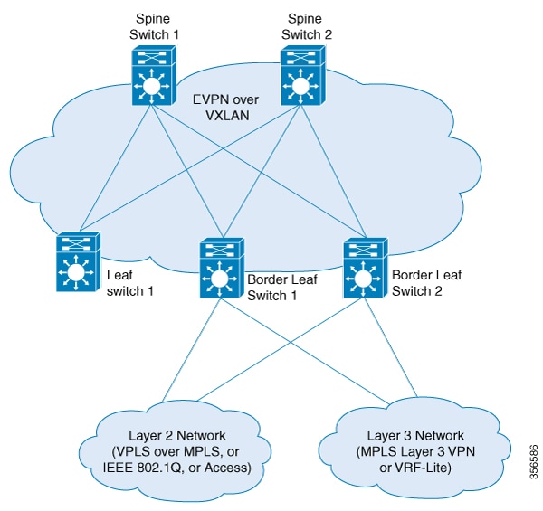
Connectivity Through a Border Leaf Switch
Leaf switches deployed as border nodes support the required control plane and data plane functionalities. Border leaf deployment
ensures that the configuration on the spine switches is much simpler. Border leaf switches only allow communication between
the external network and the VXLAN network, also known as north-south communication.
Note
A border leaf switch can also be multiple switches functioning as a single logical system with Cisco StackWise Virtual configured.
The following figure shows border leaf external connectivity of an EVPN VXLAN network with external Layer 2 and Layer 3 networks.:
Figure 1. EVPN VXLAN External Connectivity Through a Border Leaf Switch
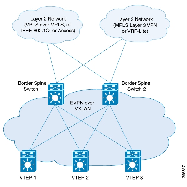
Connectivity Through a Border Spine Switch
Deploying spine switches as border nodes provides the advantage of optimizing the north-south communication with external
resources. At the same time, border spine deployment allows the spine switches to support VXLAN control and data plane functionality.
Border spine switches allow both north-south communication and east-west communication. East-west communication represents
the communication within the nodes of the EVPN VXLAN network.
The following figure shows border spine external connectivity of an EVPN VXLAN network with external Layer 2 and Layer 3 networks.:
Figure 2. EVPN VXLAN External Connectivity Through a Border Spine Switch
External Connectivity with Layer 3 Networks
Layer 3 external connectivity or handoff is established by connecting the border nodes of a BGP EVPN VXLAN fabric with an
edge router from the external Layer 3 network. The border node acts as a VTEP to perform VXLAN encapsulation and decapsulation,
but it also routes the traffic towards the edge routing device. The VXLAN-facing interface on the external Layer 3 network
can be a switch virtual interface (SVI), or a Layer 3 interface, or a Layer 3 subinterface.
You can use Layer 3 external connectivity to achieve any of the following:
Extend the logical isolation between VRFs or VLANs within the EVPN VXLAN network into the externally routed network. The external
routed network can be a traditional non-VXLAN campus network, a datacenter, or a WAN.
Provide shared access within the EVPN VXLAN network to a common external service such as the internet.
BGP EVPN VXLAN fabric supports Layer 3 external connectivity with VRF-Lite and MPLS Layer 3 VPN networks.
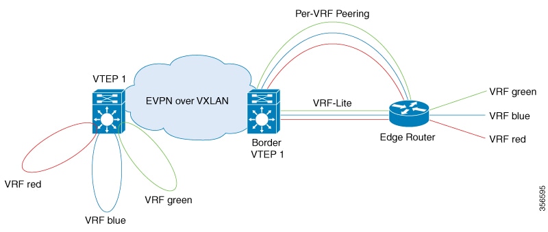
Layer 3 External Connectivity with VRF-Lite
Using VRF allows for the use of multiple routing tables that are independent and isolated. VRF-Lite is a mechanism to extend
the tenant Layer 3 VRF information beyond the BGP EVPN VXLAN Fabric. External connectivity with VRF-Lite or VRF handoff involves
a two-box approach where the border node and the edge router are physically independent devices. With VRF-Lite handoff, the
BGP EVPN VXLAN fabric extends the connectivity for different tenants externally on a hop-by-hop basis.
Once the border node learns external routes from the edge router, it advertises the prefixes inside the BGP EVPN VXLAN fabric
as EVPN type 5 routes. This information is distributed to all the other VTEPs in the network. The border node also advertises
EVPN routes to the external edge router. It sends the EVPN routes learned from the Layer 2 VPN EVPN address family to the
IPv4 or IPv6 unicast address family.
Layer 3 Multicast External Connectivity with MPLS Layer 3 VPN
Layer 3 external connectivity with an MPLS Layer 3 VPN network or MPLS handoff uses a single-box approach. The single-box
approach combines the functionalities of an EVPN VXLAN border node and an MPLS PE router into a single physical device. The
device is also known as a border PE node. The border PE node reoriginates IP prefixes from the EVPN address family of the
BGP EVPN VXLAN fabric to the VPNv4 address family of the MPLS network. Likewise, the border PE node performs the corresponding
function in the reverse direction. eBGP peering is necessary between the border PE node and the MPLS PE devices to ensure
the connectivity.
MPLS handoff allows scalability for EVPN VXLAN networks that have a large number of tenants or VRFs. Scalability is not possible
with VRF-Lite handoff.
In every VRF on a border VTEP, there are two sets of manually configured import and export route targets. The first set of
import and export route targets is associated with the BGP neighbor in the BGP EVPN VXLAN fabric. This BGP neighbor uses the
EVPN address family to exchange Layer 3 information. The second set of import and export route targets is associated with
the BGP neighbor in the Layer 3 VPN network. This BGP neighbor uses either VPNv4 or VPNv6 unicast address families to exchange
Layer 3 information. The separation of route targets allows you to configure both sets of route targets independently. In
this way, a border VTEP in an EVPN VXLAN network effectively stitches the two sets of route targets. The route targets associated
with the BGP neighbor in the Layer 3 VPN network are known as normal route targets. The route targets associated with the
BGP neighbor in the BGP EVPN VXLAN fabric are known as stitching route targets.
External Connectivity with Layer 2 Networks
Layer 2 external connectivity or handoff for an EVPN VXLAN network extends the Layer 2 domain outside of the network. BGP
EVPN VXLAN fabric supports Layer 2 external connectivity with IEE 802.1Q, access, and VPLS over MPLS networks.
Layer 2 External connectivity with IEEE 802.1Q or Access Networks
Layer 2 handoff to IEEE 802.1Q networks is achieved through a regular IEEE 802.1Q Trunk port configuration on the Switchport
interfaces on the border nodes. You can also connect EVPN VXLAN networks to external access networks.
The commonly deployed scenario has EVPN enabled at the distribution layer and has the access layer switches connected with
IEEE 802.1Q Trunk encapsulation. The IEEE 802.1Q Layer 2 traffic that comes from the access layer switches is mapped to the
corresponding VLAN. The border node then bridges the traffic towards the destination with VXLAN encapsulation. The inner packet
does not carry the IEEE 802.1Q tag. Instead, the VXLAN network identifier (VNI), which is the Layer 2 VNI in the VXLAN header,
represents the broadcast domain. Similarly, the border nodes decapsulate the traffic from the BGP EVPN VXLAN fabric and bridge
it with the corresponding IEEE 802.1Q tag to the access switches. The interface on the border VTEP that faces the external
interface can be either an access or a Trunk port. The external interface can belong to either a Layer 2 switch or a firewall.
Note
If you connect the network to an external Layer 2 switch through two border VTEPs, it represents a dual connection. In such
cases, STP does not propagate over the BGP EVPN VXLAN fabric by default.
Layer 2 External connectivity with VPLS over MPLS Network
External connectivity with VPLS networks or VPLS handoff is achieved when a border VTEP or multiple border VTEPs establish
a connection with the VPLS network. The border nodes act as the provider edge (PE) devices in the VPLS network and as VTEPs
in the EVPN VXLAN network.
BGP EVPN VXLAN supports VPLS handoff in the form of VPLS stitching through either an access VFI or an access pseudowire on
the VLAN on the border VTEP.
The access pseudowires and the pseudowires in the access VFI function as the access ports in the EVPN VXLAN network. The BGP
EVPN VXLAN fabric treats the MAC addresses learned on the pseudowires as locally learned MAC addresses. It advertises these
MAC addresses within the fabric as EVPN type 2 routes. The pseudowires are in a different split horizon group compared to
the EVPN VXLAN network. Therefore, BUM traffic floods between both the EVPN VXLAN and VPLS networks.
How to Configure EVPN VXLAN External Connectivity
This section provides information about how to configure external connectivity between an EVPN VXLAN network and an external
Layer 2 or Layer 3 network.
Redistribution of the respective interior gateway protocol (IGP) is required in the BGP VRF address family to distribute the
external prefixes into the BGP EVPN VXLAN fabric.
For more information about VRF-Lite, see Contents → IP Routing Configuration Guide → Configuring VRF-lite in the software configuration guide for the applicable release.
Configuring the VRF on the Border VTEP Interface that Faces the External Router
To cnofigure the VRF on the border VTEP interface that faces the external router, perform these steps:
Procedure
Command or Action
Purpose
Step 1
enable
Example:
Device> enable
Enables privileged EXEC mode.
Enter your password, if prompted.
Step 2
configure terminal
Example:
Device# configure terminal
Enters global configuration mode.
Step 3
interface interface-id
Example:
Device(config)# interface GigabitEthernet1/0/30
Enters the interface configuration mode for the specified interface.
Step 4
vrf forwarding vrf-name
Example:
Device(config-if)# vrf forwarding green
Associates the VRF with the interface.
Note
The interface must be associated with the same VRF for which the Layer 3 VNI has been configured for the EVPN VXLAN network.
Step 5
ip address ip-address
Example:
Device(config-if)# ip address 192.168.3.203 255.255.255.0
Configures the IP address for the interface.
Step 6
end
Example:
Device(config-if)# end
Returns to privileged EXEC mode.
Enabling Layer 3 External Connectivity with MPLS Layer 3 VPN
The following figure shows a sample topology that illustrates Layer 3 external connectivity with an MPLS Layer 3 VPN network:
Device(config-router-af)# neighbor ip-address next-hop-self all
Configures the router as the next hop for a BGP-speaking neighbor or peer group.
The all keyword is mandatory when implementing external connectivity through iBGP, where the EVPN fabric and the MPLS network are
in the same BGP autonomous system number.
The all keyword is optional when implementing external connectivity through eBGP, where the EVPN fabric and the MPLS network are
in different BGP autonomous system numbers.
Step 17
exit-address-family
Example:
Device(config-router-af)# exit-address-family
Exits address family configuration mode and returns to router configuration mode.
Step 18
address-family vpnv4
Example:
Device(config-router)# address-family vpnv4
Specifies the VPNv4 address family and enters address family configuration mode.
Device(config-router-af)# neighbor ip-address next-hop-self all
Configures the router as the next hop for a BGP-speaking neighbor or peer group.
The all keyword is mandatory when implementing external connectivity through iBGP, where the EVPN fabric and the MPLS network are
in the same BGP autonomous system number.
The all keyword is optional when implementing external connectivity through eBGP, where the EVPN fabric and the MPLS network are
in different BGP autonomous system numbers.
Step 23
exit-address-family
Example:
Device(config-router-af)# exit-address-family
Exits address family configuration mode and returns to router configuration mode.
Step 24
address-family vpnv6
Example:
Device(config-router)# address-family vpnv6
Specifies the VPNv6 address family and enters address family configuration mode.
Device(config-router-af)# neighbor ip-address next-hop-self all
Configures the router as the next hop for a BGP-speaking neighbor or peer group.
The all keyword is mandatory when implementing external connectivity through iBGP, where the EVPN fabric and the MPLS network are
in the same BGP autonomous system number.
The all keyword is optional when implementing external connectivity through eBGP, where the EVPN fabric and the MPLS network are
in different BGP autonomous system numbers.
Step 29
exit-address-family
Example:
Device(config-router-af)# exit-address-family
Exits address family configuration mode and returns to router configuration mode.
Step 30
end
Example:
Device(config-router)# end
Returns to privileged EXEC mode.
Enabling EVPN VXLAN Layer 3 TRM Interworking with MVPN Networks
To configure interworking of Layer 3 TRM with MVPN networks, perform the following steps:
Configure Layer 3 TRM in the BGP EVPN VXLAN fabric before you enable Layer 3 TRM interworking with MVPN. See How to Configure Tenant Routed Multicast for detailed steps.
Configure the MVPN network for the VPNv4 address family. See Configuring Multicast Virtual Private Network module of the IP Multicast Routing Configuration Guide.
If internal Border Gateway Protocol (iBGP) is used for peering between the two networks, run the mdt auto-discovery interworking vxlan-pim in VRF configuration mode on the border VTEP.
If external Border Gateway Protocol (eBGP) is used for peering between the two networks, run the mdt auto-discovery interworking vxlan-pim inter-as in VRF configuration mode on the border VTEP.
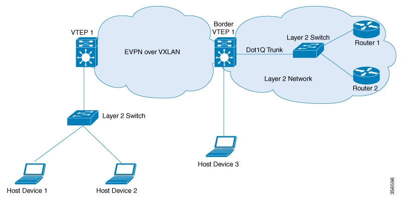
Enabling Layer 2 External Connectivity with IEEE 802.1Q Networks
The following image shows a sample topology that illustrates Layer 2 external connectivity with an IEEE 802.1Q network:
Figure 5. Layer 2 External Connectivity with IEEE 802.1Q Networks
You can also connect the EVPN VXLAN network to a firewall in place of the Layer 2 switch in the above image. To configure
Layer 2 external connectivity with an IEEE 802.1Q network, perform the following steps on the external Layer 2 switch:
Procedure
Command or Action
Purpose
Step 1
enable
Example:
Device> enable
Enables privileged EXEC mode.
Enter your password, if prompted.
Step 2
configure terminal
Example:
Device# configure terminal
Enters global configuration mode.
Step 3
interface interface-id
Example:
Device(config)# interface GigabitEthernet4/0/1
Enters interface configuration mode for the specified interface.
The specified interface must be the interface on the Layer 2 switch through which the EVPN VXLAN network communicates with
the IEEE 802.1Q network.
Step 4
switchport mode trunk
Example:
Device(config-if)# switchport mode trunk
Configures the interface as a trunking VLAN Layer 2 interface.
Sets the list of VLANs that are allowed to transmit traffic from this interface in tagged format when the interface is in
trunking mode.
Step 6
end
Example:
Device(config-if)# end
Returns to privileged EXEC mode.
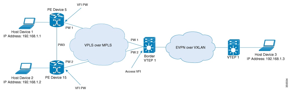
Enabling Layer 2 External Connectivity with a VPLS Network Through an Access VFI
The following illustration shows a single-homed VXLAN network connected to a VPLS over MPLS network through the access VFIs
on the border VTEP:
Figure 6. Layer 2 External Connectivity with a VPLS Network Through an Access VFI
Note
We recommend you to use Cisco Catalyst 9500 Series - High Performance switches or Cisco Catalyst 9600 Series switches as border
VTEPs when you configure Layer 2 external connectivity with a VPLS network.
We recommend you to configure Cisco Stackwise Virtual on the border VTEPs in order to achieve physical redundancy when you
configure Layer 2 external connectivity with a VPLS network.
Perform the following set of procedures to enable Layer 2 external connectivity with VPLS networks through an access VFI interface:
Define the access VFI for the VTEPs.
Configure the access VFI as a member of the VLAN on the VTEPs.
Configure the EVPN instance as a member of the VLAN on the VTEPs.
Configure VPLS on the border VTEP.
Defining an Access VFI on a Border VTEP
To configure an access facing VFI on the VLAN of a border VTEP, perform the following steps:
For more information on configuring VFIs, in the software configuration guide for the required release, go to Contents → Multiprotocol Label Switching (MPLS) Configuration Guide → Configuring Virtual Private LAN Service (VPLS) and VPLS BGP-Based Autodiscovery.
Procedure
Command or Action
Purpose
Step 1
enable
Example:
Device> enable
Enters privileged EXEC mode.
Enter password, if prompted.
Step 2
configure terminal
Example:
Device# configure terminal
Enters global configuration mode.
Step 3
l2vpn vfi context vfi-name
Example:
Device(config)# l2vpn vfi context myVFI
Establishes an Layer 2 VPN VFI between two or more separate networks, and enters VFI configuration mode.
Step 4
vpn id vpn-id
Example:
Device(config-vfi)# vpn id 1
Configures the VPN ID for the VFI.
Step 5
member ip-address encapsulation mpls
Example:
Device(config-vfi)# member 10.12.12.5 encapsulation mpls
Specifies the device that forms a point-to-point Layer 2 VPN VFI connection.
Step 6
Repeat step 5 for all devices that form a point-to-point Layer 2 VPN VFI connection.
Step 7
end
Example:
Device(config-vfi)# end
Exits VFI configuration mode and enters privileged EXEC mode.
Adding an Access VFI and an EVPN Instance as Members of the VLAN of a Border VTEP
To add an access VFI and an EVPN instance as members of the VLAN of a border VTEP, perform the following steps:
Procedure
Command or Action
Purpose
Step 1
enable
Example:
Device> enable
Enters privileged EXEC mode.
Enter password, if prompted.
Step 2
configure terminal
Example:
Device# configure terminal
Enters global configuration mode.
Step 3
vlan configuration vlan-number
Example:
Device(config)# vlan configuration 11
Enters VLAN feature configuration mode for the specified VLAN interface.
Enter the VLAN number that is associated with the Layer 2 VNI configured in the EVPN VXLAN network.
Step 4
member access-vfi vfi-name
Example:
Device(config-vlan)# member access-vfi myVFI
Adds the access VFI as a member of the VLAN configuration.
Step 5
member evpn-instance evpn-instance-number vni l2-vni-number
Example:
Device(config-vlan)# member evpn-instance 1 vni 6000
Adds the EVPN instance as a member of the VLAN configuration.
Step 6
end
Example:
Device(config-vlan)# end
Exits VLAN configuration mode and enters privileged EXEC mode.
Configuring VPLS on a Border VTEP
To configure VPLS on a border VTEP, in the software configuration guide for the required release, see Contents → Multiprotocol Label Switching (MPLS) Configuration Guide → Configuring Virtual Private LAN Service (VPLS) and VPLS BGP-Based Autodiscovery.
Configuration Examples for EVPN VXLAN External Connectivity
The following section shows the configuration examples for EVPN VXLAN external connectivity to other technologies:
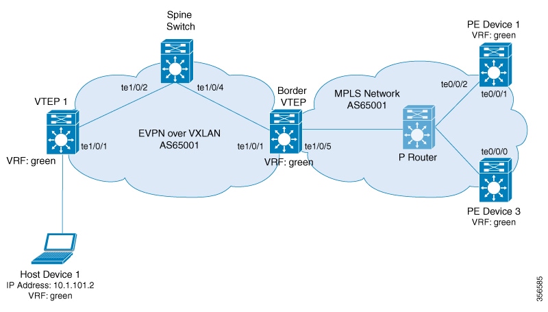
Example: Enabling Layer 3 External Connectivity with MPLS Layer 3 VPN through iBGP
This section provides an example to show how Layer 3 external connectivity with MPLS Layer 3 VPN is enabled for a BGP EVPN
VXLAN fabric through iBGP. The example shows how to configure and verify Layer 3 external connectivity with MPLS Layer 3 VPN
for the topology shown below:
Figure 7. Layer 3 External Connectivity with MPLS Layer 3 VPN through iBGP
The topology shows an EVPN VXLAN network with two VTEPS, VTEP 1 and border VTEP. Border VTEP is connected to an external PE
device that belongs to an MPLS network. The BGP EVPN VXLAN fabric and the MPLS network are in the autonomous system number
65001. All the VTEPs, PE devices and, host devices are part of the VRF green. The following tables provide sample configurations
for the devices in the topology above.
Table 1. Configuring Spine Switch, Border VTEP and PE Device 1 for Enabling Layer 3 External Connectivity with MPLS Layer 3 VPN through
iBGP
Spine Switch
Border VTEP
PE Device 1
Spine_switch# show running-config
hostname Spine_switch
!
interface Loopback0
ip address 172.16.255.1 255.255.255.255
ip ospf 1 area 0
ip pim sparse-mode
!
interface Loopback1
ip address 172.16.254.1 255.255.255.255
ip pim sparse-mode
ip ospf 1 area 0
!
interface Loopback2
ip address 172.16.255.255 255.255.255.255
ip pim sparse-mode
ip ospf 1 area 0
!
interface TenGigabitEthernet1/0/2
no switchport
ip address 172.16.14.1 255.255.255.0
ip pim sparse-mode
ip ospf network point-to-point
ip ospf 1 area 0
!
interface TenGigabitEthernet1/0/4
no switchport
ip address 172.16.16.1 255.255.255.0
ip pim sparse-mode
ip ospf network point-to-point
ip ospf 1 area 0
!
router ospf 1
router-id 172.16.255.1
!
router bgp 65001
template peer-policy RR-PP
route-reflector-client
send-community both
exit-peer-policy
!
template peer-session RR-PS
remote-as 65001
update-source Loopback0
exit-peer-session
!
bgp router-id 172.16.255.1
bgp log-neighbor-changes
no bgp default ipv4-unicast
neighbor 172.16.255.4 inherit peer-session RR-PS
neighbor 172.16.255.6 inherit peer-session RR-PS
!
!
!
Border_VTEP# show running-config
hostname Border_VTEP
!vrf definition green
rd 1:1
!
address-family ipv4
route-target export 1:1
route-target import 1:1
route-target export 1:1 stitching
route-target import 1:1 stitching
exit-address-family
!
address-family ipv6
route-target export 1:1
route-target import 1:1
route-target export 1:1 stitching
route-target import 1:1 stitching
exit-address-family
!
mpls label mode all-vrfs protocol all-afs per-vrf
!
l2vpn evpn
replication-type static
router-id Loopback1
default-gateway advertise
!
l2vpn evpn instance 101 vlan-based
encapsulation vxlan
!
l2vpn evpn instance 102 vlan-based
encapsulation vxlan
replication-type ingress
!
vlan configuration 101
member evpn-instance 101 vni 10101
vlan configuration 102
member evpn-instance 102 vni 10102
vlan configuration 901
member vni 50901
!
interface Loopback0
ip address 172.16.255.6 255.255.255.255
ip pim sparse-mode
ip ospf 1 area 0
!
interface Loopback1
ip address 172.16.254.6 255.255.255.255
ip pim sparse-mode
ip ospf 1 area 0
!
interface TenGigabitEthernet1/0/1
no switchport
ip address 172.16.16.6 255.255.255.0
ip pim sparse-mode
ip ospf network point-to-point
ip ospf 1 area 0
PE_device_1# show running-config
hostname PE_device_1
!
vrf definition green
rd 1:1
!
address-family ipv4
route-target export 1:1
route-target import 1:1
exit-address-family
!
address-family ipv6
route-target export 1:1
route-target import 1:1
exit-address-family
!
interface Loopback0
ip address 172.16.255.101 255.255.255.255
!
interface Loopback1
vrf forwarding green
ip address 10.1.255.101 255.255.255.255
!
interface TenGigabitEthernet0/0/1
ip address 172.16.111.101 255.255.255.0
ip router isis
cdp enable
mpls ip
isis network point-to-point
!
interface TenGigabitEthernet0/0/2
ip address 172.16.106.101 255.255.255.0
ip router isis
negotiation auto
cdp enable
mpls ip
isis network point-to-point
!
router isis
net 49.0001.1720.1625.5101.00
is-type level-2-only
metric-style wide
passive-interface Loopback0
!
router bgp 65001
bgp log-neighbor-changes
no bgp default ipv4-unicast
neighbor 172.16.255.103 remote-as 65001
neighbor 172.16.255.103 update-source Loopback0
!
address-family ipv4
exit-address-family
!
The following examples provide sample outputs for show commands on VTEP 1 and border VTEP to verify external connectivity for the topology configured above:
VTEP 1
The following example shows the output for the show bgp l2vpn evpn route-type command for route type 5 on VTEP 1:
VTEP_1# show bgp l2vpn evpn route-type 5 0 10.1.255.103 32
BGP routing table entry for [5][1:1][0][32][10.1.255.103]/17, version 12
Paths: (1 available, best #1, table EVPN-BGP-Table)
  Flag: 0x100
  Not advertised to any peer
  Refresh Epoch 1
  Local
    172.16.254.6 (metric 3) (via default) from 172.16.255.1 (172.16.255.1)
      Origin incomplete, metric 0, localpref 100, valid, internal, best
      EVPN ESI: 00000000000000000000, Gateway Address: 0.0.0.0, VNI Label 50901, MPLS VPN Label 0
      Extended Community: RT:1:1 ENCAP:8 Router MAC:0C75.BD67.EF48
      Originator: 172.16.255.103, Cluster list: 172.16.255.1, 172.16.255.6
      rx pathid: 0, tx pathid: 0x0
      net: 0x7F84B914EF38, path: 0x7F84BAFD0E30, pathext: 0x7F84BB42E698
      flags: net: 0x100, path: 0x3, pathext: 0xA1
      Updated on May 20 2020 19:31:08 UTC
The following example shows the output for the show bgp l2vpn evpn route-type command for route type 2 on VTEP 1:
VTEP_1# show bgp l2vpn evpn route-type 2 0 44d3ca286cc1 10.1.101.2
BGP routing table entry for [2][172.16.254.4:101][0][48][44D3CA286CC1][32][10.1.101.2]/24, version 17
Paths: (1 available, best #1, table evi_101)
  Advertised to update-groups:
     1
  Refresh Epoch 1
  Local
    :: (via default) from 0.0.0.0 (172.16.255.4)
      Origin incomplete, localpref 100, weight 32768, valid, sourced, local, best
      EVPN ESI: 00000000000000000000, Label1 10101, Label2 50901
      Extended Community: RT:1:1 RT:65001:101 ENCAP:8
        Router MAC:7C21.0DBD.9548
      Local irb vxlan vtep:
        vrf:green, l3-vni:50901
        local router mac:7C21.0DBD.9548
        core-irb interface:Vlan901
        vtep-ip:172.16.254.4
      rx pathid: 0, tx pathid: 0x0
      net: 0x7F84B914E858, path: 0x7F84BAFD09F8, pathext: 0x7F84BB42E4B8
      flags: net: 0x0, path: 0x4000028000003, pathext: 0x81
      Updated on May 20 2020 19:31:30 UTC
The following example shows the output for the show ip route vrf command on VTEP 1:
VTEP_1# show ip route vrf green

Routing Table: green
Codes: L - local, C - connected, S - static, R - RIP, M - mobile, B - BGP
       D - EIGRP, EX - EIGRP external, O - OSPF, IA - OSPF inter area
       N1 - OSPF NSSA external type 1, N2 - OSPF NSSA external type 2
       E1 - OSPF external type 1, E2 - OSPF external type 2, m - OMP
       n - NAT, Ni - NAT inside, No - NAT outside, Nd - NAT DIA
       i - IS-IS, su - IS-IS summary, L1 - IS-IS level-1, L2 - IS-IS level-2
       ia - IS-IS inter area, * - candidate default, U - per-user static route
       H - NHRP, G - NHRP registered, g - NHRP registration summary
       o - ODR, P - periodic downloaded static route, l - LISP
       a - application route
       + - replicated route, % - next hop override, p - overrides from PfR

Gateway of last resort is not set

      10.0.0.0/8 is variably subnetted, 6 subnets, 2 masks
C        10.1.101.0/24 is directly connected, Vlan101
L        10.1.101.1/32 is directly connected, Vlan101
C        10.1.102.0/24 is directly connected, Vlan102
L        10.1.102.1/32 is directly connected, Vlan102
B        10.1.255.101/32 [200/0] via 172.16.254.6, 00:21:47, Vlan901
B        10.1.255.103/32 [200/0] via 172.16.254.6, 00:21:47, Vlan901
Border VTEP
The following example shows the output for the show mpls ldp neighbor command on border VTEP:
Border_VTEP# show mpls ldp neighbor
    Peer LDP Ident: 172.16.111.101:0; Local LDP Ident 172.16.106.6:0
        TCP connection: 172.16.111.101.26371 - 172.16.106.6.646
        State: Oper; Msgs sent/rcvd: 86/69; Downstream
        Up time: 00:32:14
        LDP discovery sources:
          TenGigabitEthernet1/0/5, Src IP addr: 172.16.106.101
        Addresses bound to peer LDP Ident:
          172.16.111.101  172.16.106.101  172.16.255.101
The following example shows the output for the show bgp l2vpn evpn route-type command for route type 5 on border VTEP:
Border_VTEP# show bgp l2vpn evpn route-type 5 0 10.1.255.103 32
BGP routing table entry for [5][1:1][0][32][10.1.255.103]/17, version 7
Paths: (1 available, best #1, table EVPN-BGP-Table)
  Flag: 0x100
  Advertised to update-groups:
     1
  Refresh Epoch 1
  Local, (Received from a RR-client), imported path from base
    172.16.255.103 (metric 20) (via default) from 172.16.255.103 (172.16.255.103)
      Origin incomplete, metric 0, localpref 100, valid, internal, best
      EVPN ESI: 00000000000000000000, Gateway Address: 0.0.0.0, local vtep: 172.16.254.6, VNI Label 50901, MPLS VPN Label 23
      Extended Community: RT:1:1 ENCAP:8 Router MAC:0C75.BD67.EF48
      rx pathid: 0, tx pathid: 0x0
      net: 0x7FED6F808948, path: 0x7FED6D7EDA68, pathext: 0x7FED6D80DE40, exp_net: 0x7FED6F9BF070
      flags: net: 0x100, path: 0x7, pathext: 0xA1
      Updated on May 20 2020 19:22:47 UTC
The following example shows the output for the show bgp vpnv4 unicast all command on border VTEP for the IP address of host device 1:
Border_VTEP# show bgp vpnv4 unicast all 10.1.101.2
BGP routing table entry for 1:1:10.1.101.2/32, version 10
Paths: (1 available, best #1, table green)
  Advertised to update-groups:
     3
  Refresh Epoch 1
  Local, (Received from a RR-client), imported path from [2][172.16.254.4:101][0][48][44D3CA286CC1][32][10.1.101.2]/24 (global)
    172.16.254.4 (metric 3) (via default) from 172.16.255.1 (172.16.255.1)
      Origin incomplete, metric 0, localpref 100, valid, internal, best
      Extended Community: RT:1:1 ENCAP:8 Router MAC:7C21.0DBD.9548
      Originator: 172.16.255.4, Cluster list: 172.16.255.1
      Local vxlan vtep:
        vrf:green, vni:50901
        local router mac:0C75.BD67.EF48
        encap:8
        vtep-ip:172.16.254.6
        bdi:Vlan901
      Remote VxLAN:
        Topoid 0x4(vrf green)
        Remote Router MAC:7C21.0DBD.9548
        Encap 8
        Egress VNI 50901
        RTEP 172.16.254.4
      mpls labels in/out IPv4 VRF Aggr:34/nolabel
      rx pathid: 0, tx pathid: 0x0
      Updated on May 20 2020 19:23:11 UTC
Spine Switch
The following example shows the output for the show bgp l2vpn evpn route-type command for route type 5 on spine switch:
Spine_switch# show bgp l2vpn evpn route-type 5 0 10.1.255.103 32
BGP routing table entry for [5][1:1][0][32][10.1.255.103]/17, version 12
Paths: (1 available, best #1, table EVPN-BGP-Table)
  Advertised to update-groups:
     1
  Refresh Epoch 1
  Local, (Received from a RR-client)
    172.16.254.6 (metric 2) (via default) from 172.16.255.6 (172.16.255.6)
      Origin incomplete, metric 0, localpref 100, valid, internal, best
      EVPN ESI: 00000000000000000000, Gateway Address: 0.0.0.0, VNI Label 50901, MPLS VPN Label 0
      Extended Community: RT:1:1 ENCAP:8 Router MAC:0C75.BD67.EF48
      Originator: 172.16.255.103, Cluster list: 172.16.255.6
      rx pathid: 0, tx pathid: 0x0
      net: 0x7F54CC99CEF8, path: 0x7F54CC9AD310, pathext: 0x7F54CC9C6998
      flags: net: 0x0, path: 0x3, pathext: 0x81
      Updated on May 20 2020 19:28:59 UTC
The following example shows the output for the show bgp l2vpn evpn route-type command for route type 2 on spine switch:
Spine_switch# show bgp l2vpn evpn route-type 2 0 44d3ca286cc1 10.1.101.2
BGP routing table entry for [2][172.16.254.4:101][0][48][44D3CA286CC1][32][10.1.101.2]/24, version 14
Paths: (1 available, best #1, table EVPN-BGP-Table)
  Advertised to update-groups:
     1
  Refresh Epoch 1
  Local, (Received from a RR-client)
    172.16.254.4 (metric 2) (via default) from 172.16.255.4 (172.16.255.4)
      Origin incomplete, metric 0, localpref 100, valid, internal, best
      EVPN ESI: 00000000000000000000, Label1 10101, Label2 50901
      Extended Community: RT:1:1 RT:65001:101 ENCAP:8
        Router MAC:7C21.0DBD.9548
      rx pathid: 0, tx pathid: 0x0
      net: 0x7F54CC99CAD8, path: 0x7F54CC9AD088, pathext: 0x7F54CC9C68D8
      flags: net: 0x0, path: 0x3, pathext: 0x81
      Updated on May 20 2020 19:29:22 UTC
PE Device 3
The following example shows the output for the show bgp vpnv4 unicast all command on PE device 3 for the IP address of host device 1:
PE_device_3# show bgp vpnv4 unicast all 10.1.101.2
BGP routing table entry for 1:1:10.1.101.2/32, version 14
Paths: (1 available, best #1, table green)
  Advertised to update-groups:
     3
  Refresh Epoch 1
  Local, (Received from a RR-client)
    172.16.255.6 (metric 20) (via default) from 172.16.255.6 (172.16.255.6)
      Origin incomplete, metric 0, localpref 100, valid, internal, best
      Extended Community: RT:1:1 ENCAP:8 Router MAC:7C21.0DBD.9548
      Originator: 172.16.255.4, Cluster list: 172.16.255.6, 172.16.255.1
      mpls labels in/out nolabel/34
      rx pathid: 0, tx pathid: 0x0
      Updated on May 20 2020 11:27:25 UTC
The following example shows the output for the show ip route vrf green command on PE device 3:
PE_device_3# show ip route vrf green

Routing Table: green
Codes: L - local, C - connected, S - static, R - RIP, M - mobile, B - BGP
       D - EIGRP, EX - EIGRP external, O - OSPF, IA - OSPF inter area
       N1 - OSPF NSSA external type 1, N2 - OSPF NSSA external type 2
       E1 - OSPF external type 1, E2 - OSPF external type 2, m - OMP
       n - NAT, Ni - NAT inside, No - NAT outside, Nd - NAT DIA
       i - IS-IS, su - IS-IS summary, L1 - IS-IS level-1, L2 - IS-IS level-2
       ia - IS-IS inter area, * - candidate default, U - per-user static route
       H - NHRP, G - NHRP registered, g - NHRP registration summary
       o - ODR, P - periodic downloaded static route, l - LISP
       a - application route
       + - replicated route, % - next hop override, p - overrides from PfR

Gateway of last resort is not set

      10.0.0.0/8 is variably subnetted, 7 subnets, 2 masks
B        10.1.101.0/24 [200/0] via 172.16.255.6, 00:28:12
B        10.1.101.1/32 [200/0] via 172.16.255.6, 00:28:10
B        10.1.101.2/32 [200/0] via 172.16.255.6, 00:27:48
B        10.1.102.0/24 [200/0] via 172.16.255.6, 00:28:12
B        10.1.102.1/32 [200/0] via 172.16.255.6, 00:28:10
B        10.1.255.101/32 [200/0] via 172.16.255.101, 00:28:09
C        10.1.255.103/32 is directly connected, Loopback1
Example: Enabling Layer 3 External Connectivity with MPLS Layer 3 VPN through eBGP
This section provides an example to show how Layer 3 external connectivity with MPLS Layer 3 VPN is enabled for a BGP EVPN
VXLAN fabric through eBGP. The example shows how to configure and verify Layer 3 external connectivity with MPLS Layer 3 VPN
for the topology shown below:
Figure 8. Layer 3 External Connectivity with MPLS Layer 3 VPN through eBGP
The topology shows an EVPN VXLAN network with two VTEPS, VTEP 1 and border VTEP. Border VTEP is connected to an external PE
device that belongs to an MPLS network. The BGP EVPN VXLAN fabric is in the autonomous system number 65001. The MPLS network
is in the autonomous system number 65002. All the VTEPs, PE devices, and host devices are part of the VRF green. The following
tables provide sample configurations for the devices in the topology above.
Table 3. Configuring Spine Switch, Border VTEP and PE Device 1 for Enabling Layer 3 External Connectivity with MPLS Layer 3 VPN through
eBGP
Spine Switch
Border VTEP
PE Device 1
Spine_switch# show running-config
hostname Spine_switch
!
interface Loopback0
ip address 172.16.255.1 255.255.255.255
ip ospf 1 area 0
ip pim sparse-mode
!
interface Loopback1
ip address 172.16.254.1 255.255.255.255
ip pim sparse-mode
ip ospf 1 area 0
!
interface Loopback2
ip address 172.16.255.255 255.255.255.255
ip pim sparse-mode
ip ospf 1 area 0
!
interface TenGigabitEthernet1/0/2
no switchport
ip address 172.16.14.1 255.255.255.0
ip pim sparse-mode
ip ospf network point-to-point
ip ospf 1 area 0
!
interface TenGigabitEthernet1/0/4
no switchport
ip address 172.16.16.1 255.255.255.0
ip pim sparse-mode
ip ospf network point-to-point
ip ospf 1 area 0
!
router ospf 1
router-id 172.16.255.1
!
router bgp 65001
template peer-policy RR-PP
route-reflector-client
send-community both
exit-peer-policy
!
template peer-session RR-PS
remote-as 65001
update-source Loopback0
exit-peer-session
!
bgp router-id 172.16.255.1
bgp log-neighbor-changes
no bgp default ipv4-unicast
neighbor 172.16.255.4 inherit peer-session RR-PS
neighbor 172.16.255.6 inherit peer-session RR-PS
!
address-family ipv4
exit-address-family
!
Border_VTEP# show running-config
hostname Border_VTEP
!
vrf definition green
rd 1:1
!
address-family ipv4
route-target export 1:1
route-target import 1:1
route-target export 1:1 stitching
route-target import 1:1 stitching
exit-address-family
!
address-family ipv6
route-target export 1:1
route-target import 1:1
route-target export 1:1 stitching
route-target import 1:1 stitching
exit-address-family
!
mpls label mode all-vrfs protocol all-afs per-vrf
!
l2vpn evpn
replication-type static
router-id Loopback1
default-gateway advertise
!
l2vpn evpn instance 101 vlan-based
encapsulation vxlan
!
l2vpn evpn instance 102 vlan-based
encapsulation vxlan
replication-type ingress
!
vlan configuration 101
member evpn-instance 101 vni 10101
vlan configuration 102
member evpn-instance 102 vni 10102
vlan configuration 901
member vni 50901
!
interface Loopback0
ip address 172.16.255.6 255.255.255.255
ip pim sparse-mode
ip ospf 1 area 0
!
interface Loopback1
ip address 172.16.254.6 255.255.255.255
ip pim sparse-mode
ip ospf 1 area 0
!
interface TenGigabitEthernet1/0/1
no switchport
ip address 172.16.16.6 255.255.255.0
ip pim sparse-mode
ip ospf network point-to-point
ip ospf 1 area 0
PE_device_1# show running-config
hostname PE_device_1
!
vrf definition green
rd 1:1
!
address-family ipv4
route-target export 1:1
route-target import 1:1
exit-address-family
!
address-family ipv6
route-target export 1:1
route-target import 1:1
exit-address-family
!
interface Loopback0
ip address 172.16.255.101 255.255.255.255
!
interface Loopback1
vrf forwarding green
ip address 10.1.255.101 255.255.255.255
!
interface TenGigabitEthernet0/0/1
ip address 172.16.111.101 255.255.255.0
ip router isis
cdp enable
mpls ip
isis network point-to-point
!
interface TenGigabitEthernet0/0/2
ip address 172.16.106.101 255.255.255.0
negotiation auto
cdp enable
mpls bgp forwarding
!
router isis
net 49.0001.1720.1625.5101.00
is-type level-2-only
metric-style wide
passive-interface Loopback0
!
router bgp 65002
bgp log-neighbor-changes
no bgp default ipv4-unicas
no bgp default route-target filter
neighbor 172.16.106.6 remote-as 65001
neighbor 172.16.255.6 remote-as 65001
neighbor 172.16.255.6 ebgp-multihop 255
neighbor 172.16.255.6 update-source Loopback0
neighbor 172.16.255.103 remote-as 65002
neighbor 172.16.255.103 update-source Loopback0
The following examples provide sample outputs for show commands on the devices to verify external connectivity for the topology configured above:
VTEP 1
The following example shows the output for the show bgp l2vpn evpn route-type command for route type 5 on VTEP 1:
VTEP_1# show bgp l2vpn evpn route-type 5 0 10.1.255.103 32
BGP routing table entry for [5][1:1][0][32][10.1.255.103]/17, version 36
Paths: (1 available, best #1, table EVPN-BGP-Table)
  Not advertised to any peer
  Refresh Epoch 1
  65002
    172.16.254.6 (metric 3) (via default) from 172.16.255.1 (172.16.255.1)
      Origin incomplete, metric 0, localpref 100, valid, internal, best
      EVPN ESI: 00000000000000000000, Gateway Address: 0.0.0.0, VNI Label 50901, MPLS VPN Label 0
      Extended Community: RT:1:1 ENCAP:8 Router MAC:0C75.BD67.EF48
      Originator: 172.16.255.6, Cluster list: 172.16.255.1
      rx pathid: 0, tx pathid: 0x0
      net: 0x7F84BB35A5C8, path: 0x7F84B913E010, pathext: 0x7F84BB54A8A8
      flags: net: 0x0, path: 0x3, pathext: 0x81
      Updated on May 21 2020 13:56:28 UTC
The following example shows the output for the show bgp l2vpn evpn route-type command for route type 2 on VTEP 1:
VTEP_1# show bgp l2vpn evpn route-type 2 0 44d3ca286cc1 10.1.101.2
BGP routing table entry for [2][172.16.254.4:101][0][48][44D3CA286CC1][32][10.1.101.2]/24, version 37
Paths: (1 available, best #1, table evi_101)
  Advertised to update-groups:
     1
  Refresh Epoch 1
  Local
    :: (via default) from 0.0.0.0 (172.16.255.4)
      Origin incomplete, localpref 100, weight 32768, valid, sourced, local, best
      EVPN ESI: 00000000000000000000, Label1 10101, Label2 50901
      Extended Community: RT:1:1 RT:65001:101 ENCAP:8
        Router MAC:7C21.0DBD.9548
      Local irb vxlan vtep:
        vrf:green, l3-vni:50901
        local router mac:7C21.0DBD.9548
        core-irb interface:Vlan901
        vtep-ip:172.16.254.4
      rx pathid: 0, tx pathid: 0x0
      net: 0x7F84BB35A468, path: 0x7F84B913DF38, pathext: 0x7F84BB54A848
      flags: net: 0x0, path: 0x4000028000003, pathext: 0x81
      Updated on May 21 2020 14:00:49 UTC
The following example shows the output for the show ip route vrf command on VTEP 1:
VTEP_1# show ip route vrf green

Routing Table: green
Codes: L - local, C - connected, S - static, R - RIP, M - mobile, B - BGP
       D - EIGRP, EX - EIGRP external, O - OSPF, IA - OSPF inter area
       N1 - OSPF NSSA external type 1, N2 - OSPF NSSA external type 2
       E1 - OSPF external type 1, E2 - OSPF external type 2, m - OMP
       n - NAT, Ni - NAT inside, No - NAT outside, Nd - NAT DIA
       i - IS-IS, su - IS-IS summary, L1 - IS-IS level-1, L2 - IS-IS level-2
       ia - IS-IS inter area, * - candidate default, U - per-user static route
       H - NHRP, G - NHRP registered, g - NHRP registration summary
       o - ODR, P - periodic downloaded static route, l - LISP
       a - application route
       + - replicated route, % - next hop override, p - overrides from PfR

Gateway of last resort is not set

      10.0.0.0/8 is variably subnetted, 6 subnets, 2 masks
C        10.1.101.0/24 is directly connected, Vlan101
L        10.1.101.1/32 is directly connected, Vlan101
C        10.1.102.0/24 is directly connected, Vlan102
L        10.1.102.1/32 is directly connected, Vlan102
B        10.1.255.101/32 [200/0] via 172.16.254.6, 00:06:25, Vlan901
B        10.1.255.103/32 [200/0] via 172.16.254.6, 00:05:54, Vlan901
Border VTEP
The following example shows the output for the show bgp vpnv4 unicast all command on border VTEP for the IP address of the external device:
Border_VTEP# show bgp vpnv4 uni all 10.1.255.103/32
BGP routing table entry for 1:1:10.1.255.103/32, version 9
Paths: (1 available, best #1, table green)
  Not advertised to any peer
  Refresh Epoch 1
  65002
    172.16.255.101 (via default) from 172.16.255.101 (172.16.255.101)
      Origin incomplete, localpref 100, valid, external, best
      Extended Community: RT:1:1
      Local vxlan vtep:
        vrf:green, vni:50901
        local router mac:0C75.BD67.EF48
        encap:8
        vtep-ip:172.16.254.6
        bdi:Vlan901
      mpls labels in/out nolabel/16
      rx pathid: 0, tx pathid: 0x0
      Updated on May 21 2020 13:48:09 UTC
The following example shows the output for the show bgp l2vpn evpn route-type command for route type 5 on border VTEP:
Border_VTEP# show bgp l2vpn evpn route-type 5 0 10.1.255.103 32
BGP routing table entry for [5][1:1][0][32][10.1.255.103]/17, version 32
Paths: (1 available, best #1, table EVPN-BGP-Table)
  Advertised to update-groups:
     1
  Refresh Epoch 1
  65002, imported path from base
    172.16.255.101 (via default) from 172.16.255.101 (172.16.255.101)
      Origin incomplete, localpref 100, valid, external, best
      EVPN ESI: 00000000000000000000, Gateway Address: 0.0.0.0, local vtep: 172.16.254.6, VNI Label 50901, MPLS VPN Label 16
      Extended Community: RT:1:1 ENCAP:8 Router MAC:0C75.BD67.EF48
      rx pathid: 0, tx pathid: 0x0
      net: 0x7FED704944D0, path: 0x7FED704A4CA0, pathext: 0x7FED6DA6E250, exp_net: 0x7FED6F812678
      flags: net: 0x0, path: 0x7, pathext: 0x81
      Updated on May 21 2020 13:48:09 UTC
The following example shows the output for the show mpls forwarding-table command on border VTEP:
Border_VTEP# show mpls forwarding-table
Local      Outgoing   Prefix           Bytes Label   Outgoing   Next Hop
Label      Label      or Tunnel Id     Switched      interface
16         No Label   IPv4 VRF[V]      156           aggregate/green
17         Pop Label  172.16.106.101/32   \
                                       228           Te1/0/5    172.16.106.101
18         Pop Label  172.16.255.101/32   \
                                       0             Te1/0/5    172.16.106.101
The following example shows the output for the show bgp vpnv4 unicast all command on border VTEP for the IP address of host device 1:
Border_VTEP# show bgp vpnv4 uni all 10.1.101.2/32
BGP routing table entry for 1:1:10.1.101.2/32, version 10
Paths: (1 available, best #1, table green)
  Advertised to update-groups:
     1
  Refresh Epoch 4
  Local, imported path from [2][172.16.254.4:101][0][48][44D3CA286CC1][32][10.1.101.2]/24 (global)
    172.16.254.4 (metric 3) (via default) from 172.16.255.1 (172.16.255.1)
      Origin incomplete, metric 0, localpref 100, valid, internal, best
      Extended Community: RT:1:1 ENCAP:8 Router MAC:7C21.0DBD.9548
      Originator: 172.16.255.4, Cluster list: 172.16.255.1
      Local vxlan vtep:
        vrf:green, vni:50901
        local router mac:0C75.BD67.EF48
        encap:8
        vtep-ip:172.16.254.6
        bdi:Vlan901
      Remote VxLAN:
        Topoid 0x9(vrf green)
        Remote Router MAC:7C21.0DBD.9548
        Encap 8
        Egress VNI 50901
        RTEP 172.16.254.4
      mpls labels in/out IPv4 VRF Aggr:16/nolabel
      rx pathid: 0, tx pathid: 0x0
      Updated on May 21 2020 13:52:30 UTC
Spine Switch
The following example shows the output for the show bgp l2vpn evpn route-type command for route type 5 on spine switch:
Spine_switch# show bgp l2vpn evpn route-type 5 0 10.1.255.103 32
BGP routing table entry for [5][1:1][0][32][10.1.255.103]/17, version 23
Paths: (1 available, best #1, table EVPN-BGP-Table)
  Advertised to update-groups:
     1
  Refresh Epoch 1
  65002, (Received from a RR-client)
    172.16.254.6 (metric 2) (via default) from 172.16.255.6 (172.16.255.6)
      Origin incomplete, metric 0, localpref 100, valid, internal, best
      EVPN ESI: 00000000000000000000, Gateway Address: 0.0.0.0, VNI Label 50901, MPLS VPN Label 0
      Extended Community: RT:1:1 ENCAP:8 Router MAC:0C75.BD67.EF48
      rx pathid: 0, tx pathid: 0x0
      net: 0x7F54CC95FAB8, path: 0x7F54CCA542F8, pathext: 0x7F54CC9707B0
      flags: net: 0x0, path: 0x3, pathext: 0x81
      Updated on May 21 2020 13:54:20 UTC
The following example shows the output for the show bgp l2vpn evpn route-type command for route type 2 on spine switch:
Spine_switch# show bgp l2vpn evpn route-type 2 0 44d3ca286cc1 10.1.101.2
BGP routing table entry for [2][172.16.254.4:101][0][48][44D3CA286CC1][32][10.1.101.2]/24, version 24
Paths: (1 available, best #1, table EVPN-BGP-Table)
  Advertised to update-groups:
     1
  Refresh Epoch 1
  Local, (Received from a RR-client)
    172.16.254.4 (metric 2) (via default) from 172.16.255.4 (172.16.255.4)
      Origin incomplete, metric 0, localpref 100, valid, internal, best
      EVPN ESI: 00000000000000000000, Label1 10101, Label2 50901
      Extended Community: RT:1:1 RT:65001:101 ENCAP:8
        Router MAC:7C21.0DBD.9548
      rx pathid: 0, tx pathid: 0x0
      net: 0x7F54CC95F958, path: 0x7F54CCA54220, pathext: 0x7F54CC970750
      flags: net: 0x0, path: 0x3, pathext: 0x81
      Updated on May 21 2020 13:58:41 UTC
PE Device 1
The following example shows the output for the show bgp vpnv4 unicast all command on PE device 1 for the IP address of host device 1:
PE_device_1# show bgp vpnv4 unicast all 10.1.255.103/32
BGP routing table entry for 1:1:10.1.101.2/32, version 14
Paths: (1 available, best #1, table green)
  Advertised to update-groups:
     1
  Refresh Epoch 1
  65001
    172.16.255.6 (via default) from 172.16.255.6 (172.16.255.6)
      Origin incomplete, localpref 100, valid, external, best
      Extended Community: RT:1:1 ENCAP:8 Router MAC:7C21.0DBD.9548
      mpls labels in/out 22/16
      rx pathid: 0, tx pathid: 0x0
      Updated on May 21 2020 05:57:06 UTC
The following example shows the output for the show ip route vrf command on PE device 1:
PE_device_1# show ip route vrf green

Routing Table: green
Codes: L - local, C - connected, S - static, R - RIP, M - mobile, B - BGP
       D - EIGRP, EX - EIGRP external, O - OSPF, IA - OSPF inter area
       N1 - OSPF NSSA external type 1, N2 - OSPF NSSA external type 2
       E1 - OSPF external type 1, E2 - OSPF external type 2, m - OMP
       n - NAT, Ni - NAT inside, No - NAT outside, Nd - NAT DIA
       i - IS-IS, su - IS-IS summary, L1 - IS-IS level-1, L2 - IS-IS level-2
       ia - IS-IS inter area, * - candidate default, U - per-user static route
       H - NHRP, G - NHRP registered, g - NHRP registration summary
       o - ODR, P - periodic downloaded static route, l - LISP
       a - application route
       + - replicated route, % - next hop override, p - overrides from PfR

Gateway of last resort is not set

      10.0.0.0/8 is variably subnetted, 7 subnets, 2 masks
B        10.1.101.0/24 [20/0] via 172.16.255.6, 00:28:09
B        10.1.101.1/32 [20/0] via 172.16.255.6, 00:28:09
B        10.1.101.2/32 [20/0] via 172.16.255.6, 00:23:17
B        10.1.102.0/24 [20/0] via 172.16.255.6, 00:28:09
B        10.1.102.1/32 [20/0] via 172.16.255.6, 00:28:09
C        10.1.255.101/32 is directly connected, Loopback1
B        10.1.255.103/32 [200/0] via 172.16.255.103, 00:28:09
PE Device 3
The following example shows the output for the show bgp vpnv4 unicast all command on PE device 3 for the IP address of host device 1:
PE_device_3# show bgp vpnv4 unicast all 10.1.101.2/32
BGP routing table entry for 1:1:10.1.101.2/32, version 14
Paths: (1 available, best #1, table green)
  Not advertised to any peer
  Refresh Epoch 1
  65001, (Received from a RR-client)
    172.16.255.101 (metric 10) (via default) from 172.16.255.101 (172.16.255.101)
      Origin incomplete, metric 0, localpref 100, valid, internal, best
      Extended Community: RT:1:1 ENCAP:8 Router MAC:7C21.0DBD.9548
      mpls labels in/out nolabel/22
      rx pathid: 0, tx pathid: 0x0
      Updated on May 21 2020 05:56:46 UTC
The following example shows the output for the show ip route vrf command on PE device 3:
PE_device_3# show ip route vrf green

Routing Table: green
Codes: L - local, C - connected, S - static, R - RIP, M - mobile, B - BGP
       D - EIGRP, EX - EIGRP external, O - OSPF, IA - OSPF inter area
       N1 - OSPF NSSA external type 1, N2 - OSPF NSSA external type 2
       E1 - OSPF external type 1, E2 - OSPF external type 2, m - OMP
       n - NAT, Ni - NAT inside, No - NAT outside, Nd - NAT DIA
       i - IS-IS, su - IS-IS summary, L1 - IS-IS level-1, L2 - IS-IS level-2
       ia - IS-IS inter area, * - candidate default, U - per-user static route
       H - NHRP, G - NHRP registered, g - NHRP registration summary
       o - ODR, P - periodic downloaded static route, l - LISP
       a - application route
       + - replicated route, % - next hop override, p - overrides from PfR

Gateway of last resort is not set

      10.0.0.0/8 is variably subnetted, 7 subnets, 2 masks
B        10.1.101.0/24 [200/0] via 172.16.255.101, 00:29:09
B        10.1.101.1/32 [200/0] via 172.16.255.101, 00:29:09
B        10.1.101.2/32 [200/0] via 172.16.255.101, 00:24:17
B        10.1.102.0/24 [200/0] via 172.16.255.101, 00:29:09
B        10.1.102.1/32 [200/0] via 172.16.255.101, 00:29:09
B        10.1.255.101/32 [200/0] via 172.16.255.101, 00:29:09
C        10.1.255.103/32 is directly connected, Loopback1


 Feedback