- What's New in This Chapter
- IP Phone Services
- Extension Mobility
- Unified CM Services for Extension Mobility
- Extension Mobility Architecture
- Extension Mobility Cross Cluster (EMCC)
- Extension Mobility Security
- Support for Phones in Secure Mode
- High Availability for Extension Mobility
- Capacity Planning for Extension Mobility
- Design Considerations for Extension Mobility
- Design Considerations for Extension Mobility Cross Cluster (EMCC)
- Unified CM Assistant
Cisco Unified CM Applications
Cisco Unified Communications Manager (Unified CM) applications provide numerous operational and functional enhancements to basic IP telephony. External eXtensible Markup Language (XML) productivity applications or IP Phone Services can be run on the web server and/or client on most Cisco Unified IP Phones. For example, the IP phone on a user's desk can be used to get stock quotes, weather information, flight information, and other types of web-based information. In addition, custom IP phone service applications can be written that allow users to track inventory, bill customers for time, or control conference room environments (lights, video screen, temperature, and so forth). Unified CM also has a number of integrated applications that provide additional functionality, including:
•![]() Cisco Extension Mobility (EM)
Cisco Extension Mobility (EM)
The Extension Mobility feature enables mobile users to configure a Cisco Unified IP Phone as their own, on a temporary basis, by logging in to that phone.
•![]() Cisco Unified Communications Manager Assistant (Unified CM Assistant)
Cisco Unified Communications Manager Assistant (Unified CM Assistant)
Unified CM Assistant is a Unified CM integrated application that enables assistants to handle one or more managers' incoming phone calls.
•![]() Cisco WebDialer
Cisco WebDialer
WebDialer is a click-to-call application for Unified CM that enables users to place calls easily from their PCs using any supported phone device.
In some cases these integrated applications also invoke IP Phone Services to provide additional functionality.
This chapter examines the following Unified CM applications:
What's New in This Chapter
Table 19-1 lists the topics that are new in this chapter or that have changed significantly from previous releases of this document.
IP Phone Services
Cisco Unified IP Phone Services are applications that utilize the web client and/or server and XML capabilities of the Cisco Unified IP Phone. The Cisco Unified IP Phone firmware contains a micro-browser that enables limited web browsing capability. These phone service applications provide the potential for value-added services and productivity enhancement by running directly on the user's desktop phone. For purposes of this chapter, the term phone service refers to an application that transmits and receives content to and from the Cisco Unified IP Phone.
This section examines the following design aspects of the IP Phone Services feature:
•![]() IP Phone Services Architecture
IP Phone Services Architecture
•![]() High Availability for IP Phone Services
High Availability for IP Phone Services
•![]() Capacity Planning for IP Phone Services
Capacity Planning for IP Phone Services
•![]() Design Considerations for IP Phone Services
Design Considerations for IP Phone Services
IP Phone Services Architecture
An IP Phone service can be initiated in several ways:
•![]() User-initiated (pull)
User-initiated (pull)
An IP Phone user presses the Services button, which sends an HTTP GET message to Unified CM for displaying a list of user-subscribed phone services. Figure 19-1 illustrates this functionality.
•![]() Phone-initiated (pull)
Phone-initiated (pull)
An idle time value can be set within the IP Phone firmware, as indicated by the URL Idle Time parameter. When this timeout value is exceeded, the IP Phone firmware itself initiates an HTTP GET to the idle URL location specified by the URL Idle parameter.
•![]() Phone service-initiated (push)
Phone service-initiated (push)
A phone service application can push content to the IP Phone by sending an HTTP POST message to the phone.

Note ![]() Unlike with the user-initiated and phone-initiated pull functionality, whereby the phone's web client is used to invoke phone services, the phone service-initiated push functionality invokes action on the phone by posting content (via an HTTP POST) to the phone's web server (not to its client).
Unlike with the user-initiated and phone-initiated pull functionality, whereby the phone's web client is used to invoke phone services, the phone service-initiated push functionality invokes action on the phone by posting content (via an HTTP POST) to the phone's web server (not to its client).
Figure 19-1 shows a detailed illustration of the user-initiated IP Phone service operation. With Services Provisioning set to External URL or Both when a user presses the Services button, an HTTP GET message is sent from the IP Phone to the Unified CM getservicesmenu.jsp script by default (step 1). You can specify a different script by changing the Phone URL enterprise parameter. The getservicesmenu.jsp script returns the list of phone service URL locations to which the individual user has subscribed (step 2). The HTTP response returns this list to the IP Phone (step 3). Any further phone service menu options chosen by the user continue the HTTP messaging between the user and the web server containing the selected phone service application (step 4).
By default the Services Provisioning parameter is set to Internal. With this setting, the IP phone obtains the list of phone services from its configuration file instead of sending an HTTP GET message to Unified CM.
Note ![]() If the Service Provisioning enterprise parameter is set to Internal, steps 1 through 3 are bypassed and the operation of phone services begins with step 4.
If the Service Provisioning enterprise parameter is set to Internal, steps 1 through 3 are bypassed and the operation of phone services begins with step 4.
Note ![]() The Cisco Unified IP Phone 7960 does not have the ability to parse the list of phone services from its configuration file, so it sends an HTTP GET to Unified CM to get that list, even if the Service Provisioning enterprise parameter is set to Internal.
The Cisco Unified IP Phone 7960 does not have the ability to parse the list of phone services from its configuration file, so it sends an HTTP GET to Unified CM to get that list, even if the Service Provisioning enterprise parameter is set to Internal.
Figure 19-1 User-Initiated IP Phone Service Architecture

Figure 19-2 shows examples of both phone-initiated and phone service-initiated push functionality. In the phone-initiated example, the phone automatically sends an HTTP GET to the location specified under the URL Idle parameter when the URL Idle Time is reached. The HTTP GET is forwarded via Unified CM to the external web server. The web server sends back an HTTP Response, which is relayed by Unified CM back to the phone, and the phone displays the text and/or image on the screen.
In the phone service-initiated push example, the phone service on the external web server sends an HTTP POST with a Common Gateway Interface (CGI) or Execute call to the phone's web server. Before performing the CGI or Execute call, the phone authenticates the request using the proxy authentication service specified by the URL Authentication parameter. This proxy authentication service provides an interface between the phone and the Unified CM directory in order to validate requests made directly to the phone. If the request is authenticated, Unified CM forwards an HTTP Response to the phone. The phone's web server then performs the requested action, and the phone returns an HTTP response back to the external web server. If authentication fails, Unified CM forwards a negative HTTP Response, and the phone does not perform the requested CGI or Execute action but in turn forwards a negative HTTP Response to the external web server.
Figure 19-2 Phone-Initiated and Phone Service-Initiated IP Phone Service Architecture

In addition to XML Services, a new service can be created with a Service Category of Java MIDlet. When a Java MIDlet-type service is invoked, the configured Service URL contains the URL from which the MIDlet JAD file can be retrieved. When the application server receives the JAD file request, the server should return the appropriate JAR file for that device, which the phone's MIDlet-installer will download and process.
For more information on Java MIDlet support on Cisco IP Phones, refer to the Cisco IP Phone data sheets at http://www.cisco.com.
Note ![]() After a phone has downloaded its configuration file via TFTP, the phone parses the services configuration to determine whether or not the list of services has changed, and if so, it updates its local (persisted) services configuration. If any of the changed services were Java MIDlets (which are explicitly provisioned and stored on the phone), then the phone sequentially walks through the necessary install, upgrade, downgrade, and uninstall operations to comply with what was provisioned in the configuration file. If a MIDlet install fails, it will re-attempt the install the next time the phone checks its configuration file (during boot, reset, or restart).
After a phone has downloaded its configuration file via TFTP, the phone parses the services configuration to determine whether or not the list of services has changed, and if so, it updates its local (persisted) services configuration. If any of the changed services were Java MIDlets (which are explicitly provisioned and stored on the phone), then the phone sequentially walks through the necessary install, upgrade, downgrade, and uninstall operations to comply with what was provisioned in the configuration file. If a MIDlet install fails, it will re-attempt the install the next time the phone checks its configuration file (during boot, reset, or restart).
The administrator has the added ability to specify the Service Type of configured services to be one of the following: IP Phone Services, Directories, or Messages. This gives the administrator the flexibility to control which button users must press on the IP phone to access new services. New services can optionally be configured as Enterprise Subscriptions, which forces them to appear automatically on all IP phones without the need to update subscriptions for each individual phone. In addition, services can be enabled or disabled without the need to delete the service from the Unified CM database.
Note ![]() Default services such as Missed Calls, Placed Calls, and Corporate Directory can also be disabled. This allows the administrator to create a custom service with a Service URL matching that of the corresponding default service, thus allowing phones to subscribe to these default services on an as-needed basis.
Default services such as Missed Calls, Placed Calls, and Corporate Directory can also be disabled. This allows the administrator to create a custom service with a Service URL matching that of the corresponding default service, thus allowing phones to subscribe to these default services on an as-needed basis.
Unified CM provides the ability to configure a secure IP Phone Services URL using HTTPS in addition to a non-secure URL. Phones that support HTTPS will automatically use the secure URL. For more information about Trust Verification Services and security certificate handling for IP phones, along with a complete list of phones that support HTTPS, refer to the HTTPS information in the latest version of the Cisco Unified Communications Manager Security Guide, available at
http://cisco.com/en/US/products/sw/voicesw/ps556/prod_maintenance_guides_list.html
High Availability for IP Phone Services
To ensure reliable services for phone users, you must maintain a high level of system availability, with a seamless transition to redundant systems during a system failure.
With Services Provisioning set to Internal, the phone will receive its subscribed phone services from the phone's configuration file and store these (and their corresponding service URLs) in flash. This allows the phone to access the service URLs directly on a web server without first querying the Cisco CallManager IP Phone Service. With Services Provisioning set to Internal, the Corporate and Personal Directories default services also have an extra level of redundancy built into the phones. When these services are selected, the phone will attempt to send an HTTP message with the proper URL string to the Unified CM with which it is currently registered. Therefore, the Unified CM Group configuration of the phone's device pool provides redundancy for these services.
If Services Provisioning is set to External URL or both, while most of the back-end processing of a phone service occurs on a web server, the phones still depend upon Unified CM to inform them of the service URLs for their subscribed phone services. Given the architecture of IP phone service functionality and the message flows shown in Figure 19-1 and Figure 19-2, the following two main failure scenarios should be considered.
Failure Scenario 1: Server with Cisco CallManager Cisco IP Phone Services Fails
Redundancy in this case depends upon some type of server load balancing (SLB), as illustrated in Figure 19-3, where a virtual IP address (or DNS-resolvable hostname) is used to point to one or more Unified CM servers. This virtual IP address (or DNS-resolvable hostname) is used when configuring the URL Services parameter. The SLB device is configured with the real IP addresses of the Unified CM subscriber nodes. Thus, a Unified CM server failure does not prevent the IP Phone Services subscription list from being returned to the phone when the phone's Services button is pushed. In addition, phone services such as Extension Mobility and Unified CM Assistant that run on a Unified CM server are also potentially made redundant by this method. (See High Availability for Extension Mobility, and High Availability for Unified CM Assistant.)
Most SLB devices, such as the Cisco Application Control Engine (ACE), can be configured to monitor the status of multiple servers and automatically redirect requests during failure events. For more information on the Cisco Application Control Engine (ACE), refer to the documentation available at
http://www.cisco.com/en/US/products/ps5719/Products_Sub_Category_Home.html
Figure 19-3 Method for Providing Redundancy for Phone Services

Failure Scenario 2: External Web Server Hosting a Particular IP Phone Service Fails
In this scenario, the connection to the Unified CM server is preserved, but the link fails to the web server hosting the user-subscribed phone service. This is an easier scenario to provision for redundancy because the IP phone is still able to access the Unified CM server when the Services button is pressed. In this case, the IP phone is similar to any other HTTP client accessing a web server. As a result, you can again use some type of SLB functionality (similar to the one indicated in Figure 19-3) to redirect the HTTP request from the phone to one or more redundant web servers hosting the user-subscribed phone service.
Capacity Planning for IP Phone Services
Cisco Unified IP Phone Services act, for the most part, as an HTTP client. In most cases it uses Unified CM only as a redirect server to the location of the subscribed service. Because Unified CM acts as a redirect server to the phone service, there typically is minimal performance impact on Unified CM when a user initiates a phone service request by pressing the Services key, but a large number of requests (hundreds of requests per minute or more) could affect the server performance. To minimize the impact on the server performance, if an external URL does not need to be specified for the IP Phone Services, Cisco generally recommends leaving the Services Provisioning Enterprise Parameter set to Internal. If Services Provisioning has to be set to External URL or Both, or if you are using a large number phones that do not have the ability to retrieve the list of services from their configuration file (such as the Cisco Unified IP Phone 7960), carefully select the node that will provide the Cisco Unified IP Phone Services list. For example, consider using the Unified CM TFTP servers instead of the Unified CM publisher if the load on the publisher is already high, or consider using Unified CM subscribers that are not handling a lot of traffic.
Note ![]() In the case of Extension Mobility and Unified CM Assistant phone service, Unified CM acts as more than a redirect server, and additional performance impacts should be considered. See the sections on Extension Mobility, and Unified CM Assistant, for specific performance and scalability considerations for these applications.
In the case of Extension Mobility and Unified CM Assistant phone service, Unified CM acts as more than a redirect server, and additional performance impacts should be considered. See the sections on Extension Mobility, and Unified CM Assistant, for specific performance and scalability considerations for these applications.
Because the IP Phone is either an HTTP client or server, estimating the required bandwidth used by an IP Phone service is similar to estimating the bandwidth of an HTTP browser accessing the same text as HTTP content residing on a web hosting server.
Design Considerations for IP Phone Services
With the exception of the integrated Extension Mobility and Unified CM Assistant applications' Phone Services, IP Phone services must reside on a separate off-cluster non-Unified CM web server. Running phone services other than Extension Mobility and Unified CM Assistant on the Unified CM server node is not supported.
Most Cisco IP phones support content with text and graphics. Some phones such as the Cisco Unified IP Phone 7911G support only text-based XML applications.
Extension Mobility
The Cisco Extension Mobility (EM) feature enables users to configure a Cisco Unified IP Phone as their own, on a temporary basis, by logging in to that phone. After a user logs in, the phone adopts the user's individual device profile information, including line numbers, speed dials, services links, and other user-specific properties of a phone. For example, when user X occupies a desk and logs in to the phone, that user's directory number(s), speed dials, and other properties appear on that phone; but when user Y uses the same desk at a different time, user Y's information appears. The EM feature dynamically configures a phone according to the authenticated user's device profile. The benefit of this application is that it allows users to be reached at their own extension on any phone within the Unified CM cluster, regardless of physical location, provided the phone supports EM.
This section examines the following design aspects of the Extension Mobility feature:
•![]() Unified CM Services for Extension Mobility
Unified CM Services for Extension Mobility
•![]() Extension Mobility Architecture
Extension Mobility Architecture
•![]() Extension Mobility Cross Cluster (EMCC)
Extension Mobility Cross Cluster (EMCC)
•![]() High Availability for Extension Mobility
High Availability for Extension Mobility
•![]() Capacity Planning for Extension Mobility
Capacity Planning for Extension Mobility
•![]() Design Considerations for Extension Mobility
Design Considerations for Extension Mobility
Unified CM Services for Extension Mobility
The EM application relies on the Cisco Extension Mobility service, which is a feature service and which you must activate manually from the Serviceability page.
EM also relies on the Cisco Extension Mobility Application network service, which is activated automatically on all Unified CM nodes during installation.
The Cisco Extension Mobility Application service is a network service that provides an interface between the EM user phone and the Cisco Extension Mobility service. In addition, the Cisco Extension Mobility Application service subscribes to the change notification indications within the cluster and maintains a list of nodes in the cluster that have an active Cisco Extension Mobility service.
Extension Mobility Architecture
Figure 19-4 depicts the message flows and architecture of the EM application. When a phone user wants to access the EM application, the following sequence of events occurs:
1. ![]() When the user presses the Services button on the phone, this action generates a call to the URL specified under the URL Services parameter on the Enterprise Parameter configuration page (see step 1 in Figure 19-4).
When the user presses the Services button on the phone, this action generates a call to the URL specified under the URL Services parameter on the Enterprise Parameter configuration page (see step 1 in Figure 19-4).
2. ![]() An HTTP/XML call is generated to the IP Phone Services, which returns a list of all services to which the user's phone is subscribed (see step 2 in Figure 19-4).
An HTTP/XML call is generated to the IP Phone Services, which returns a list of all services to which the user's phone is subscribed (see step 2 in Figure 19-4).
Note ![]() With the Services Provisioning enterprise parameter set to Internal, steps 1 and 2 are bypassed. Alternatively, with Services Provisioning set to External URL or Both, a Service URL button can be configured for EM on a user's phone so that the user can press a line or speed-dial button to generate a direct call to the Cisco Extension Mobility Application service, also bypassing steps 1 and 2.
With the Services Provisioning enterprise parameter set to Internal, steps 1 and 2 are bypassed. Alternatively, with Services Provisioning set to External URL or Both, a Service URL button can be configured for EM on a user's phone so that the user can press a line or speed-dial button to generate a direct call to the Cisco Extension Mobility Application service, also bypassing steps 1 and 2.
3. ![]() Next the user selects the Extension Mobility phone service listing. This selection in turn generates an HTTP call to the Cisco Extension Mobility Application service, which serves as the interface between the phone and the Cisco Extension Mobility service (see step 3 in Figure 19-4).
Next the user selects the Extension Mobility phone service listing. This selection in turn generates an HTTP call to the Cisco Extension Mobility Application service, which serves as the interface between the phone and the Cisco Extension Mobility service (see step 3 in Figure 19-4).
4. ![]() The Cisco Extension Mobility Application service then forwards an XML response back to the phone requesting user login credentials (userID and PIN) or, if the user is already logged in, a response asking if the user wants to log off the phone (see step 4 in Figure 19-4).
The Cisco Extension Mobility Application service then forwards an XML response back to the phone requesting user login credentials (userID and PIN) or, if the user is already logged in, a response asking if the user wants to log off the phone (see step 4 in Figure 19-4).
5. ![]() Assuming the user is attempting to log in, the user must use the phone's keypad to enter a valid userID and PIN. After the user presses the Submit softkey, a response containing the userID and PIN just entered is forwarded back to the Cisco Extension Mobility Application service (see step 5 in Figure 19-4).
Assuming the user is attempting to log in, the user must use the phone's keypad to enter a valid userID and PIN. After the user presses the Submit softkey, a response containing the userID and PIN just entered is forwarded back to the Cisco Extension Mobility Application service (see step 5 in Figure 19-4).
6. ![]() The Cisco Extension Mobility Application service next forwards this login information to the Cisco Extension Mobility service, which interacts with the Unified CM database to verify the user's credentials (see step 6 in Figure 19-4). The Cisco Extension Mobility Application service subscribes to cluster change notification, and it maintains a list of all nodes in the cluster with the Cisco Extension Mobility service activated. Therefore, in case the Cisco Extension Mobility service is not running on the same Unified CM node, the Cisco Extension Mobility Application service forwards the login information to other Unified CM nodes that are running the Cisco Extension Mobility service.
The Cisco Extension Mobility Application service next forwards this login information to the Cisco Extension Mobility service, which interacts with the Unified CM database to verify the user's credentials (see step 6 in Figure 19-4). The Cisco Extension Mobility Application service subscribes to cluster change notification, and it maintains a list of all nodes in the cluster with the Cisco Extension Mobility service activated. Therefore, in case the Cisco Extension Mobility service is not running on the same Unified CM node, the Cisco Extension Mobility Application service forwards the login information to other Unified CM nodes that are running the Cisco Extension Mobility service.
7. ![]() Upon successful verification of the user's credentials, the Cisco Extension Mobility service also interacts with the Unified CM database to read and select the appropriate user device profile and to write needed changes to the phone configuration based on this device profile (see step 7 in Figure 19-4).
Upon successful verification of the user's credentials, the Cisco Extension Mobility service also interacts with the Unified CM database to read and select the appropriate user device profile and to write needed changes to the phone configuration based on this device profile (see step 7 in Figure 19-4).
8. ![]() Once these changes have been made, the Cisco Extension Mobility service sends back a successful response to the Cisco Extension Mobility Application service (see step 8 in Figure 19-4).
Once these changes have been made, the Cisco Extension Mobility service sends back a successful response to the Cisco Extension Mobility Application service (see step 8 in Figure 19-4).
9. ![]() The Cisco Extension Mobility Application service, in turn, sends a reset message to the phone, and the phone resets and accepts the new phone configuration (see step 9 in Figure 19-4).
The Cisco Extension Mobility Application service, in turn, sends a reset message to the phone, and the phone resets and accepts the new phone configuration (see step 9 in Figure 19-4).
Figure 19-4 EM Application Architecture and Message Flow

Extension Mobility Cross Cluster (EMCC)
Unified CM provides the ability to perform Extension Mobility logins between clusters within an enterprise with a new feature called Extension Mobility Cross Cluster (EMCC). It is important to understand the high-level architecture of EMCC. The EMCC feature employs the concepts of a home cluster and a visiting cluster, and these terms are defined from the perspective of the user performing the login. When a user travels to an office and attempts to log in to a phone, if the cluster to which this phone is registered does not contain the user's information in its database, then this cluster is considered a visiting cluster and the phone is hereinafter referred to as the visiting phone. Figure 19-5 illustrates the concept of home and visiting clusters.
Figure 19-5 EMCC Home Cluster and Visiting Cluster

The EM service in the visiting cluster attempts to locate the home cluster of the user by sending out queries to each of the EMCC remote clusters that have been configured in Unified CM. When the user's home cluster responds positively, this initiates communications between the EM services of both clusters to exchange information that essentially brings the device information into the home cluster database and allows the home cluster to build a configuration file for this visiting phone. This configuration file incorporates some device configuration from the visiting cluster, configuration parameters from the home cluster, and the user's device profile in the home cluster. Once the home cluster TFTP server has a configuration file for this visiting phone, a reset issued by the visiting cluster forces the visiting phone to download a small configuration from the visiting cluster, which further instructs it to download certificates and a full configuration from the home cluster. Ultimately, the visiting phone cross-registers with the home cluster. This means that all call control signaling occurs between a home cluster Unified CM subscriber and the visiting phone, and the user's home cluster dialing habits are maintained.
For a step-by-step description of the EMCC login process, refer to the Extension Mobility Cross Cluster information in the latest version of the Cisco Unified Communications Manager Features and Services Guide, available at
http://cisco.com/en/US/products/sw/voicesw/ps556/prod_maintenance_guides_list.html
Call Processing
EMCC call processing behavior is also critical to understand because it impacts dial plan design. When a user has logged into a phone in a visiting cluster, any digits dialed by the user are analyzed by the home cluster according to the visiting phone's assembled call search space (CSS), which is a concatenation of the Adjunct CSS in the home cluster's device pool for the visiting phone (referred to as the EMCC roaming device pool), the Line CSS configured on the directory number associated with the user's device profile, and the EMCC CSS configured on the user's device profile. Figure 19-6 illustrates the resulting CSS for an EMCC phone.
Figure 19-6 Resulting CSS for an EMCC Phone
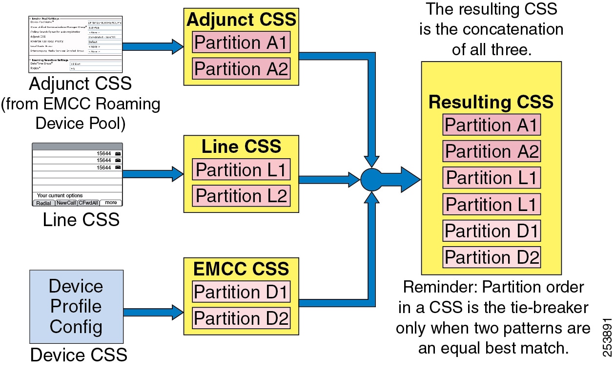
The Adjunct Calling Search Space is a new call routing configuration parameter that is used by EMCC to intercept and route emergency numbers for users from a visiting cluster. The Adjunct CSS contains a partition with directory numbers such as 911, 112, or 999, that route the calls to the visiting cluster and allow the call to reach emergency services local to the physical phone's location. For more information on Adjunct Calling Search Spaces and the EMCC roaming device pool and how it is associated with a visiting phone, refer to the Extension Mobility Cross Cluster information in the latest version of the Cisco Unified Communications Manager Features and Services Guide, available at
http://cisco.com/en/US/products/sw/voicesw/ps556/prod_maintenance_guides_list.html
Note ![]() The EMCC roaming device pool associated with the EMCC feature is not related to the roaming device pool associated with the Device Mobility feature.
The EMCC roaming device pool associated with the EMCC feature is not related to the roaming device pool associated with the Device Mobility feature.
EMCC users must be aware that, when placing calls, they will be leveraging their home Unified CM routes and numbering plan. For example, if a user from Cluster A logs into a phone from Cluster B and wants to place a call to the directory number of a Cluster B phone located right next to it, the user would have to dial the appropriate pattern as if the user was placing the call from Cluster A to the phone in Cluster B. This implies that the home cluster may initiate an intercluster trunk call from Cluster A to Cluster B, but the media will flow locally between the visiting phone and the remote phone.
If the EMCC clusters have been deployed using +E.164 numbering, then the users should already be accustomed to dialing the full number of the target number and will not need to alter their dialing habits.
With PSTN routed calls, there are two different configurations that affect call processing behavior:
•![]() Route patterns that do not use the Local Route Group (LRG) feature
Route patterns that do not use the Local Route Group (LRG) feature
•![]() Route patterns that use the LRG feature
Route patterns that use the LRG feature
When an EMCC logged-in user dials a PSTN call, if the digit analysis matches a route pattern that ultimately leads to a voice gateway (either via the route list and route group construct or configured directly to a voice gateway), the call is offered out the gateway. If the Standard Local Route Group (Standard LRG) feature is not in use, and the call involves a voice gateway associated with the home cluster; therefore media will flow between the visiting phone (typically across a WAN) back to the voice gateway. When the route pattern leads to a route list configured to use Standard LRG, the behavior changes. (For more information about LRG, see Local Route Group.) When Unified CM logic must invoke a Standard LRG for an EMCC logged-in device, it recognizes the endpoint as an EMCC device and sends the PSTN call across a designated EMCC-specific SIP trunk to the visiting cluster to which this visiting phone is normally registered.
Note ![]() Only one SIP trunk with an EMCC trunk service type is required per cluster. There is no destination information configured on this trunk; that information is gathered dynamically when adding and updating an EMCC remote cluster.
Only one SIP trunk with an EMCC trunk service type is required per cluster. There is no destination information configured on this trunk; that information is gathered dynamically when adding and updating an EMCC remote cluster.
When a call invite is received on the EMCC SIP trunk in the visiting cluster, the visiting cluster again performs digit analysis on the called number according to the CSS of the trunk (or alternatively, according to the CSS of the visiting phone's original device configuration), and routes the call accordingly. There is additional information included in a SIP invite across an EMCC SIP trunk, namely the device name of the visiting phone. This enables the visiting cluster to determine the configured device CSS of the visiting phone in the database (if required); and if the digit analysis results in matching a route pattern that ultimately points to the Standard LRG, the visiting cluster is able to determine the configured Standard LRG for this visiting phone. The Standard LRG in the visiting cluster will typically contain voice gateways associated with the visiting cluster, therefore the PSTN call is offered out a voice gateway local to the visiting phone.
The difference between LRG and non-LRG call processing behavior is critical when considering calls to emergency numbers. While the use of Local Route Groups (LRGs) is not required cluster-wide for an EMCC deployment, the EMCC logged-in phones must have access to an LRG in order to route emergency calls correctly. An LRG is required to correctly route an emergency call to a visiting cluster so that the call can be placed through an appropriate voice gateway local to the visiting phone. The Adjunct Calling Search Space in the roaming device pool configuration for an EMCC device enables an administrator to add emergency route patterns that will use an LRG for EMCC logged-in devices, but it will not affect emergency dialing for other devices in the home cluster. As discussed earlier, an EMCC logged-in phone will be associated with a device pool (by means of geolocations) that represents all phone devices from another cluster. The device pool's Adjunct Calling Search Space allows for the visiting cluster's emergency route pattern to be configured so that only emergency calls for an EMCC logged-in phone will be sent through an LRG. So even if the home and visiting clusters use the same emergency route pattern, the EMCC logged-in phone's emergency call will route through the LRG to the visiting cluster. Once the call is received at the visiting cluster through the EMCC SIP trunk, the visiting cluster dial plan will be responsible for further processing of the call.
Note ![]() If any cluster supporting EMCC is also using Cisco Emergency Responder for emergency call processing, refer to the Cisco Emergency Responder Administration Guide for information on how to configure the dial plan to support the deployment, available at http://www.cisco.com/en/US/products/sw/voicesw/ps842/prod_maintenance_guides_list.html.
If any cluster supporting EMCC is also using Cisco Emergency Responder for emergency call processing, refer to the Cisco Emergency Responder Administration Guide for information on how to configure the dial plan to support the deployment, available at http://www.cisco.com/en/US/products/sw/voicesw/ps842/prod_maintenance_guides_list.html.
Note ![]() If Standard LRGs are already deployed for the emergency route pattern, and if the home and visiting clusters use the same emergency dial string, use of the Adjunct CSS is not required.
If Standard LRGs are already deployed for the emergency route pattern, and if the home and visiting clusters use the same emergency dial string, use of the Adjunct CSS is not required.
For detailed EMCC call processing examples and configuration, refer to the Extension Mobility Cross Cluster information in the latest version of the Cisco Unified Communications Manager Features and Services Guide, available at
http://cisco.com/en/US/products/sw/voicesw/ps556/prod_maintenance_guides_list.html
Media Resources
All media resources except for RSVP agents are allocated from the home cluster according to the media resource group list of the device pool assigned to the visiting phone. Conferencing, transcoding, and music on hold all function as normal, with the difference being that media is streaming between the visiting phone and media resources across (typically) a WAN separating the home and visiting clusters. When an EMCC logged-in user makes a call that requires use of an RSVP agent, the Unified CM EMCC logic is able to determine it is a visiting phone, and it sends a resource request across the EMCC SIP trunk to the remote cluster to which the visiting phone belongs. The device name of the visiting phone is included in this request, which enables the visiting cluster to verify the RSVP agent media resources that are normally assigned to this visiting phone and to allocate its use for the call. For more information on RSVP-based call admission control for EMCC, see Architecture and Considerations for Extension Mobility Cross Cluster.
Extension Mobility Security
Unified CM provides the ability to create an Extension Mobility secure service URL using HTTPS. This encrypts the entire EM login/logout exchange. Cisco recommends configuring a secure service URL for Extension Mobility. If there are phones deployed for EM that do not support HTTPS, a non-secure service URL must also be configured. When secure and non-secure service URLs exist for the service, phones that support HTTPS use the secure service URL by default. For a complete list of phones that support HTTPS, refer to the HTTPS information in the latest version of the Cisco Unified Communications Manager Security Guide, available at
http://cisco.com/en/US/products/sw/voicesw/ps556/prod_maintenance_guides_list.html
The EM feature provides an optional level of security for EM login and logout requests by validating the source IP address of the request. By default, EM does not perform this request validation; therefore, to enable EM security, the administrator must set the cluster-wide service parameter Validate IP Address to true.
For organizations that implement a web proxy to handle EM login and logout HTTP requests, the Allow Proxy service parameter must be set to true. A proxy server, while forwarding the HTTP request, will set the via-field of the HTTP header with its hostname. If there are multiple proxy servers between the device and Unified CM, and if the request is forwarded by all the servers, then the via-field in the HTTP header will have a comma-separated list of hostnames for each of the proxy servers in the forwarding path. The Allow Proxy service parameter, if set to true, will allow EM login and logouts received via a web proxy. In addition, if the proxied EM requests use the source IP address of the proxy server, this IP address must also be configured in the Trusted List of IPs service parameter.
With support for HTTPS and Security By Default starting in Unified CM 8.x, and with the introduction of secure phones support for EMCC in Unified CM 9.x, the intercluster interactions of EMCC require some extra steps to ensure that clusters can communicate with each other in a secure manner. In particular, all clusters that participate in EMCC must export their Tomcat (web) and TFTP certificates to a central sFTP server. Exporting the CAPF certificates is also required if phones used for EMCC will be in secure mode. These security certificates are all combined, and then each cluster must import the combined certificate into its cluster. It is important to remember that any time a new node that may participate in EMCC is added to the cluster, or if a certificate on any existing node is updated, the process of exporting, combining, and importing must be repeated. All of these steps have been streamlined via Unified CM Serviceability administration. For details on EMCC configuration, refer to the Extension Mobility Cross Cluster information in the latest version of the Cisco Unified Communications Manager Features and Services Guide, available at
http://cisco.com/en/US/products/sw/voicesw/ps556/prod_maintenance_guides_list.html
Support for Phones in Secure Mode
Starting with Cisco Unified CM 9.x, users can log in through EMCC using phones in secure mode — that is, phones with an authenticated or encrypted Device Security Profile. When a user logs in on a phone in secure mode, the configuration in the device security profile (such as the device security mode, TFTP encrypted option, and transport protocol) is transferred to the home cluster, allowing the phone to operate in the same secure mode as it was originally in the visiting cluster. For example, if the phone is configured with the encrypted device security mode in the visiting cluster and the user logs in through EMCC, the phone still operates in the encrypted device security mode with a secure TLS channel for signaling and sRTP for media. However, one condition is that the home cluster security mode must be configured as mixed mode. If the home cluster is configured as non-secure instead, the EMCC login will fail. If the phone is not in secure mode, the phone continues to operate in a non-secure mode after the EMCC login, regardless of whether the visiting cluster is in mixed mode or non-secure mode. Table 19-2 indicates this behavior.
Unified CM 8.x supports EMCC but not with phones in secure mode. For this reason, EMCC login attempts from a phone in secure mode registered to a visiting cluster running Unified CM 8.x will fail, regardless of whether the home cluster is running Unified CM 8.x or 9.x. Similarly, EMCC login attempts from a phone in secure mode to a home cluster running Unified CM 8.x will fail, regardless of whether the visiting cluster is running Unified CM 8.x or 9.x. Table 19-2 indicates this behavior.
Note ![]() As of Cisco Unified CM 9.0, the EMCC SIP trunk cannot be configured with a secure profile. Therefore, calls to the local PSTN do not use a secure channel for signaling. However, the media is encrypted if the phone and PSTN gateway are configured in a secure mode.
As of Cisco Unified CM 9.0, the EMCC SIP trunk cannot be configured with a secure profile. Therefore, calls to the local PSTN do not use a secure channel for signaling. However, the media is encrypted if the phone and PSTN gateway are configured in a secure mode.
High Availability for Extension Mobility
According to the EM architecture illustrated in Figure 19-4, reads and writes to the Unified CM database are required. EM is a user-facing feature, and database writes pertaining to EM can be performed by subscriber nodes. Therefore, if the Unified CM publisher is unavailable, EM logins and logouts are still possible.
From a redundancy perspective, the following component levels of redundancy must be considered for full EM resiliency:
•![]() Cisco CallManager Cisco IP Phone Services
Cisco CallManager Cisco IP Phone Services
High availability for the CallManager Cisco IP Phone Services is obtained by using the Services Provisioning service parameter or by using an SLB device pointing to multiple Unified CM nodes running the Cisco CallManager Cisco IP Phone Services. For more details, see High Availability for IP Phone Services.
•![]() Cisco Extension Mobility service
Cisco Extension Mobility service
High availability for the Cisco Extension Mobility service is obtained by activating the Cisco Extension Mobility service on multiple Unified CM nodes.
Note ![]() While the Cisco Extension Mobility service can be activated on more than two nodes, a maximum of two nodes can actively handle login/logout requests at any given time. The other nodes running the Cisco Extension Mobility service should start handling login/logout requests only in case of failure.
While the Cisco Extension Mobility service can be activated on more than two nodes, a maximum of two nodes can actively handle login/logout requests at any given time. The other nodes running the Cisco Extension Mobility service should start handling login/logout requests only in case of failure.
Cisco recommends deploying a server load balancer device such as the Cisco Application Control Engine (ACE) to load-balance the requests across two Unified CM nodes and to provide redundancy. Without a server load balancer, load balancing would be uneven and the redundancy would be manual. For example, two EM IP Phone services could be configured on each phone. If one Unified CM node is not reachable, the end user would have to manually select the other EM IP Phone service to reach the other node.
Note ![]() While it is possible to provide redundancy for the EM IP Phone service by relying on end users to manually select an EM IP Phone service from a list of EM IP Phone services, achieving high availability in this manner can be problematic. Because there is no control over which EM IP Phone service a user might select from the phone services menu (or assigned feature keys), there is no way to ensure that the EM login/logout load is balanced between Unified CM nodes handling EM login/logout requests. Further, end user behavior when encountering delay in response of the EM service, which is typical in a failure scenario, will usually exacerbate the situation as users cancel EM service calls and select alternate EM IP Phone service. This can lead to added congestion and load on the network as well as on the remaining Unified CM node handling EM login/logout requests.
While it is possible to provide redundancy for the EM IP Phone service by relying on end users to manually select an EM IP Phone service from a list of EM IP Phone services, achieving high availability in this manner can be problematic. Because there is no control over which EM IP Phone service a user might select from the phone services menu (or assigned feature keys), there is no way to ensure that the EM login/logout load is balanced between Unified CM nodes handling EM login/logout requests. Further, end user behavior when encountering delay in response of the EM service, which is typical in a failure scenario, will usually exacerbate the situation as users cancel EM service calls and select alternate EM IP Phone service. This can lead to added congestion and load on the network as well as on the remaining Unified CM node handling EM login/logout requests.
A deployment with two Unified CM nodes running the Cisco Extension Mobility service provides the highest capacity in terms of number of login/logout requests per minute. (See Capacity Planning for Extension Mobility, for details.) It also provides redundancy. However, in case of failure, the login/logout request capacity is reduced because there is only one node left. Therefore, to achieve the highest login/logout capacity and maintain this capacity in case of failure, the Cisco Extension Mobility service should be activated on additional Unified CM nodes. To load balance evenly across the active nodes and to ensure that only two nodes are handling login/logout requests at any given time, a server load balancer device such as the Cisco Application Control Engine (ACE) should be deployed. The Cisco Application Control Engine has the capability to detect if a primary server is down and to start sending requests to backup servers in case of failure. For details on the Cisco Application Control Engine (ACE) configuration, refer to the documentation available at
http://www.cisco.com/en/US/products/ps5719/Products_Sub_Category_Home.html
Note ![]() Cisco does not recommend a redundancy design using DNS A or SRV records with multiple IP listings. With multiple IP addresses returned to a DNS request, the phones must wait for a timeout period before trying the next IP address in the list, and in most cases this results in unacceptable delays to the end user. In addition, this can result in more than two subscriber nodes with the Cisco Extension Mobility Application service enabled to handle login/logout requests, which is not supported.
Cisco does not recommend a redundancy design using DNS A or SRV records with multiple IP listings. With multiple IP addresses returned to a DNS request, the phones must wait for a timeout period before trying the next IP address in the list, and in most cases this results in unacceptable delays to the end user. In addition, this can result in more than two subscriber nodes with the Cisco Extension Mobility Application service enabled to handle login/logout requests, which is not supported.
With EMCC, remote clusters are administratively added via Unified CM web administration by specifying a single FQDN or IP address of a Unified CM subscriber node running the EM service in the remote cluster. The EM services between the two clusters provide information about the Unified CM version, an ordered list of EM Service nodes for EMCC EM Service communications, which EMCC SIP trunk services are enabled (PSTN Access and/or RSVP Agent) in the remote cluster, and an ordered list of up to three remote Unified CM nodes that handle EMCC SIP trunk operations for each EMCC service. EMCC EM service communications over HTTPS include locating users' home clusters, exchanging information during EMCC logins, and remote cluster updates. Upon an initial update, a remote cluster's Extension Mobility Application service is queried, which will return the first three EM Service nodes in its list. This ordered list determines which remote cluster EM Service nodes will be used for EMCC communications.
The remote cluster obtains the information regarding primary, secondary, and tertiary options for EMCC PSTN Access and RSVP Agent services from the Unified CM Group that is associated with the device pool of the assigned EMCC SIP trunk for those services. This ensures that, if the primary Unified CM subscriber handling the EMCC SIP trunk is offline, then the EMCC SIP trunk call will be handled by the secondary Unified CM subscriber, and so on.
Once a phone is logged in through EMCC, redundancy is provided for the phone in the form of the Unified CM Group configured in its assigned EMCC device pool. If the visiting phone is located in a remote site and there is a WAN outage in which both the visiting and home cluster are unreachable, then the SRST reference from the visiting cluster is maintained by the EMCC phone. Therefore, an EMCC logged-in phone will still be able to register with the appropriate SRST router in the site where it is located. The EMCC logged-in user's DID most likely will not be associated with the local gateway(s) at the SRST site, so incoming calls will still be routed based on the call forwarding rules on the user's home cluster. While in SRST mode, the user will also have to adapt to the visiting SRST site's configured dial habits during SRST failover registration. For additional examples of an EMCC logged-in phone's behavior during a networking failure, refer to the Cisco Extension Mobility Cross Cluster section in the Cisco Unified Communications Manager Features and Services Guide, available at
http://cisco.com/en/US/products/sw/voicesw/ps556/prod_maintenance_guides_list.html
Cisco also recommends configuring a default and backup Unified CM TFTP server to be used for visiting phones to download EMCC configuration files that will allow them to register with the home cluster. This is configured under EMCC Feature Configuration.
Capacity Planning for Extension Mobility
With a single Unified CM running the Cisco Extension Mobility application, the maximum cluster-wide capacity is 250 logins and/or logouts per minute with an MCS 7845-H2/I2 or MCS 7845-I3 server, or with a virtual machine using an equivalent OVA. Cisco Extension Mobility login and logout functionality can be distributed across a pair of subscriber nodes to increase login/logout cluster capacity. An SLB device can be used, or to manually distribute the EM load evenly between the two subscriber nodes, the phones should be divided into two groups, with one group of phones subscribed to an EM phone service pointing to one of the subscriber nodes and the other group of phones subscribed to a second EM phone service that is pointing to a second subscriber node. When the EM load is distributed in this way, evenly between two MCS 7845-H2/I2/I3 servers or two virtual machines using an equivalent OVA, the maximum cluster-wide capacity is 375 sequential logins and/or logouts per minute.
Note ![]() The Cisco Extension Mobility service can be activated on more than two nodes for redundancy purposes, but Cisco supports a maximum of two subscriber nodes actively handling logins/logouts at any given time.
The Cisco Extension Mobility service can be activated on more than two nodes for redundancy purposes, but Cisco supports a maximum of two subscriber nodes actively handling logins/logouts at any given time.
Note ![]() Enabling EM Security does not diminish performance.
Enabling EM Security does not diminish performance.
The EMCC login/logout process requires more processing resources than intracluster EM login/logout, therefore the maximum supported login/logout rates are lower. In the absence of any intracluster EM logins/logouts, Unified CM supports a maximum rate of 75 EMCC logins/logouts per minute with Cisco MCS 7845-H2/I2 and MCS 7845-I3 servers or the OVA equivalent. Most deployments will have a combination of intracluster and intercluster logins/logouts occurring. For this more common scenario, the mix of EMCC logins/logouts (whether acting as home cluster or visiting cluster) should be modeled for 40 per minute while the intracluster EM logins should modeled for 185 logins/logouts when using a single EM login server. The intracluster EM login rate can be increased to 280 login/logouts per minute when using MCS 7845-H2/I2 or MCS 7845-I3 servers or the OVA equivalent in dual EM service configuration.
For more details on the capacity limits, see the chapter on Unified Communications Design and Deployment Sizing Considerations.
EMCC logged-in devices (visiting phones) consume twice as many resources as any other endpoint in a cluster. The maximum supported number of EMCC logged-in devices is 2,500 per cluster, but this also decreases the theoretical maximum number of other devices per cluster from 30,000 to 25,000. Even if the number of other registered devices in the cluster is reduced, the maximum supported number of EMCC logged-in devices is still 2,500.
There is no technical limit to the number of EMCC remote clusters that can be added to a cluster; however, the full-mesh requirement will increase the load on the EM service as the number of remote clusters increases. For a high number of sites (more than 10), the EM CPU should be monitored by means of the Cisco Real-Time Monitoring Tool (RTMT).
Design Considerations for Extension Mobility
The following guidelines and restrictions apply with regard to the deployment and operation of EM within the Unified CM telephony environment:
•![]() EM users should not move between locations or sites within a cluster when Automated Alternate Routing (AAR) and/or the Voice over PSTN (VoPSTN) deployment model are in use.
EM users should not move between locations or sites within a cluster when Automated Alternate Routing (AAR) and/or the Voice over PSTN (VoPSTN) deployment model are in use.
EM functionality relies on the use of the IP network for routing calls. Call routing via the PSTN is more problematic because E.164 PSTN numbers are static and the PSTN is unable to account for movement of EM user directory numbers (DNs) from their home sites. AAR relies on the PSTN for call routing, as does the VoPSTN deployment model. In both cases, EM user movement between locations and sites is supported only if all sites the user is traversing are in the same AAR group. For additional information, see Extension Mobility.
•![]() Restarting the Cisco Extension Mobility service or the node on which the service is running will affect auto-logout settings.
Restarting the Cisco Extension Mobility service or the node on which the service is running will affect auto-logout settings.
If the Cisco Extension Mobility service is stopped or restarted, the system does not auto-logout users who are already logged in after the expiration of the maximum login interval. These phones will either have to be logged out manually or wait until the daily database clean-up process runs (typically at midnight).
WebDialer supports the use of phones logged in using Extension Mobility. For more information, please see WebDialer.
Design Considerations for Extension Mobility Cross Cluster (EMCC)
The following design considerations apply when deploying EMCC.
General Design Considerations
•![]() EMCC requires that all users must be unique across all clusters in the enterprise. If LDAP synchronization is maintaining common users for multiple clusters, some type of filtering must be applied.
EMCC requires that all users must be unique across all clusters in the enterprise. If LDAP synchronization is maintaining common users for multiple clusters, some type of filtering must be applied.
•![]() Consider the network delay between clusters in combination with the features you plan to use. As the visiting phone is registered with the home cluster, features will work. However, depending on the network delay for a given deployment, all applications and features might not meet user requirements. Testing might be required to determine the usability of features for a given network.
Consider the network delay between clusters in combination with the features you plan to use. As the visiting phone is registered with the home cluster, features will work. However, depending on the network delay for a given deployment, all applications and features might not meet user requirements. Testing might be required to determine the usability of features for a given network.
For example, EMCC supports dynamic CTI control of a visiting phone. But if an offhook is issued via an application and it takes 1 second before the phone goes offhook, this might be acceptable for an office worker but might not be acceptable for a call center agent.
•![]() Phone load firmware is not enforced during the login process. Instead, the visiting cluster phone load information is maintained so that cross-registration does not result in new phone firmware downloads.
Phone load firmware is not enforced during the login process. Instead, the visiting cluster phone load information is maintained so that cross-registration does not result in new phone firmware downloads.
•![]() If the home cluster locale is different than that of the visiting cluster, the phone will download the new locale from the visiting cluster TFTP server. If it is not available, then the phone will not change locales and instead will maintain the visiting cluster locale.
If the home cluster locale is different than that of the visiting cluster, the phone will download the new locale from the visiting cluster TFTP server. If it is not available, then the phone will not change locales and instead will maintain the visiting cluster locale.
•![]() DLUs are not consumed in the home cluster for the registered visiting phones.
DLUs are not consumed in the home cluster for the registered visiting phones.
•![]() The total number of EMCC logins is controlled by the total number of EMCC inserted devices in the Bulk Administration Tool (BAT).
The total number of EMCC logins is controlled by the total number of EMCC inserted devices in the Bulk Administration Tool (BAT).
•![]() EMCC supports only RSVP-based call admission control. Unified CM locations-based call admission control is not supported.
EMCC supports only RSVP-based call admission control. Unified CM locations-based call admission control is not supported.
•![]() Except for RSVP agents, all other media resources are allocated from the home cluster according to the media resource group list associated with the EMCC roaming device pool.
Except for RSVP agents, all other media resources are allocated from the home cluster according to the media resource group list associated with the EMCC roaming device pool.
•![]() Audio and video codecs are determined by the EMCC region settings. These settings override normal region configuration for EMCC registered phones. All EMCC region parameters must be configured with the same values in all clusters. If they are different, RSVP Agent for that cluster will be disabled by the remote cluster update operation.
Audio and video codecs are determined by the EMCC region settings. These settings override normal region configuration for EMCC registered phones. All EMCC region parameters must be configured with the same values in all clusters. If they are different, RSVP Agent for that cluster will be disabled by the remote cluster update operation.
•![]() For the EMCC roaming device pool to be assigned correctly, EMCC-capable phones must have a geo-location configured via device configuration or a device pool.
For the EMCC roaming device pool to be assigned correctly, EMCC-capable phones must have a geo-location configured via device configuration or a device pool.
Call Processing Design Considerations
•![]() Incoming calls for a user's directory number will always be received on a home cluster voice gateway, therefore RTP media will flow between the visiting phone and the home gateway for incoming calls.
Incoming calls for a user's directory number will always be received on a home cluster voice gateway, therefore RTP media will flow between the visiting phone and the home gateway for incoming calls.
•![]() Calls sent across the EMCC SIP trunk will have gone through digit manipulation in the home cluster. The called number may require manipulation to match visiting cluster route patterns.
Calls sent across the EMCC SIP trunk will have gone through digit manipulation in the home cluster. The called number may require manipulation to match visiting cluster route patterns.
•![]() Verify configured codec capabilities of H.323 and SIP gateways in the home cluster. For example, if home cluster gateways are configured to accept only G.711 calls and the EMCC region bandwidth is set to 8 kbps (G.729), a transcoder is required to complete the call. Alternatively, the H.323 or SIP gateway dial peers may be configured to allow for G.729 in addition to G.711.
Verify configured codec capabilities of H.323 and SIP gateways in the home cluster. For example, if home cluster gateways are configured to accept only G.711 calls and the EMCC region bandwidth is set to 8 kbps (G.729), a transcoder is required to complete the call. Alternatively, the H.323 or SIP gateway dial peers may be configured to allow for G.729 in addition to G.711.
•![]() Design considerations must be made regarding the calling party for EMCC emergency calls. Depending on dial plan configurations, the calling party number leaving the visiting cluster gateway may be the user's DID that is normally associated with the home cluster. This would require transforming the calling number incoming on the EMCC SIP trunk, on route patterns, or egressing on the visiting gateways.
Design considerations must be made regarding the calling party for EMCC emergency calls. Depending on dial plan configurations, the calling party number leaving the visiting cluster gateway may be the user's DID that is normally associated with the home cluster. This would require transforming the calling number incoming on the EMCC SIP trunk, on route patterns, or egressing on the visiting gateways.
•![]() When EMCC is deployed with Cisco Emergency Responder, Emergency Responder should be deployed in all clusters handled by a single Emergency Responder cluster. If the visiting cluster is deployed with Emergency Responder and the home cluster is not, Emergency Responder will not be able to identify the visiting phone when the call arrives back to the visiting cluster.
When EMCC is deployed with Cisco Emergency Responder, Emergency Responder should be deployed in all clusters handled by a single Emergency Responder cluster. If the visiting cluster is deployed with Emergency Responder and the home cluster is not, Emergency Responder will not be able to identify the visiting phone when the call arrives back to the visiting cluster.
Unified CM Assistant
Cisco Unified Communications Manager Assistant (Unified CM Assistant) is a Unified CM integrated application that enables assistants to handle incoming calls on behalf of one or more managers. With the use of the Unified CM Assistant Console desktop application or the Unified CM Assistant Console phone service on the assistant phone, assistants can quickly determine a manager's status and determine what to do with a call. Assistants can manipulate calls using their phone's softkeys and service menus or via the PC interface with either keyboard shortcuts, drop-down menus, or by dragging and dropping calls to the managers' proxy lines.
This section examines the following design aspects of the Unified CM Assistant feature:
•![]() Unified CM Assistant Architecture
Unified CM Assistant Architecture
•![]() High Availability for Unified CM Assistant
High Availability for Unified CM Assistant
•![]() Capacity Planning for Unified CM Assistant
Capacity Planning for Unified CM Assistant
•![]() Design Considerations for Unified CM Assistant
Design Considerations for Unified CM Assistant
Unified CM Assistant Architecture
The Unified CM Assistant application can operate in two modes: proxy line mode and shared line mode. The operation and functionality of each mode is different, and each has specific advantages and disadvantages. Both modes can be configured within a single cluster. However, mixing modes on the same assistant is not allowed. A single assistant providing support for one or more managers can support those managers in either shared line mode or proxy line mode.
Unified CM Assistant Proxy Line Mode
Figure 19-7 illustrates a simple call flow with Unified CM Assistant in proxy line mode. In this example, Phone A calls the Manager phone with directory number (DN) 60001 (step 1). The CTI/Unified CM Assistant Route Point (RP) intercepts this call based on a configured DN of 6XXXX. Next, based on the Manager DN, the call is redirected by the route point to the Manager's proxy line (DN: 39001) on the Assistant's phone (step 2). The Assistant can then answer or handle the call and, if appropriate, redirect the call to the Manager's phone (step 3). In the event of Unified CM Assistant application failure or if the Unified CM Assistant RP fails, a fall-through mechanism exists via the Call Forward No Answer (CFNA) 6XXXX configuration of the RP, so that calls to the Manager's DN will fall-through directly to the Manager's phone (step 4).
Figure 19-7 Unified CM Assistant Proxy Line Mode

Note ![]() The CFNA fall-through mechanism illustrated in Figure 19-7 requires configuration of the same summarized digit-string as the Unified CM Assistant RP directory number in both the Forward No Answer Internal and Forward No Answer External fields under the Unified CM Assistant RP directory number configuration page. In addition, the calling search space (CSS) field for each of these call forward parameters should be configured with the calling search space containing the partition with which the Manager phone DNs are configured, so that the Manager phone DNs can be reached if the Unified CM Assistant RP or Unified CM Assistant application fails.
The CFNA fall-through mechanism illustrated in Figure 19-7 requires configuration of the same summarized digit-string as the Unified CM Assistant RP directory number in both the Forward No Answer Internal and Forward No Answer External fields under the Unified CM Assistant RP directory number configuration page. In addition, the calling search space (CSS) field for each of these call forward parameters should be configured with the calling search space containing the partition with which the Manager phone DNs are configured, so that the Manager phone DNs can be reached if the Unified CM Assistant RP or Unified CM Assistant application fails.
Unified CM Assistant Share Lined Mode
Figure 19-8 illustrates a simple call flow with Unified CM Assistant in shared line mode. In this example, Phone A calls the Manager phone with directory number (DN) 60001, which is a shared line on the Assistant phone (step 1). The call will ring at both the Assistant and Manager phones unless the Manager has invoked the Do Not Disturb (DND) feature, in which case the Assistant's phone will be the only phone that rings audibly (step 2).
Figure 19-8 Unified CM Assistant Shared Line Mode

In Unified CM Assistant shared line mode, the Unified CM Assistant RP is not needed or required for intercepting calls to the Manager phone. However, the Do Not Disturb (DND) feature on the Manager phone and the Unified CM Assistant Console desktop application still depend on the Cisco IP Manager Assistant (IPMA) and Cisco CTIManager services. Furthermore, in Unified CM Assistant shared line mode, features such as call filtering, call intercept, assistant selection, and Assistant Watch are not available.
Unified CM Assistant Architecture
The architecture of the Unified CM Assistant application is as important to understand as its functionality. Figure 19-9 depicts the message flows and architecture of Unified CM Assistant. When Unified CM Assistant has been configured for Unified CM Assistant Manager and Assistant users, the following sequence of interactions and events can occur:
1. ![]() Manager and Assistant phones register with the Cisco CallManager Service, and the phone's keypad and softkeys are used to handle call flows (see step 1 in Figure 19-9).
Manager and Assistant phones register with the Cisco CallManager Service, and the phone's keypad and softkeys are used to handle call flows (see step 1 in Figure 19-9).
2. ![]() Both the Unified CM Assistant Console desktop application and the Manager Configuration web-based application communicate and interface with the Cisco IP Manager Assistant service (see step 2 in Figure 19-9).
Both the Unified CM Assistant Console desktop application and the Manager Configuration web-based application communicate and interface with the Cisco IP Manager Assistant service (see step 2 in Figure 19-9).
3. ![]() The Cisco IP Manager Assistant service in turn interacts with the CTIManager service for exchanging line monitoring and phone control information (see step 3 in Figure 19-9).
The Cisco IP Manager Assistant service in turn interacts with the CTIManager service for exchanging line monitoring and phone control information (see step 3 in Figure 19-9).
4. ![]() The CTIManager service passes Unified CM Assistant phone control information to the Cisco CallManager service and also controls the Unified CM Assistant RP (see step 4 in Figure 19-9).
The CTIManager service passes Unified CM Assistant phone control information to the Cisco CallManager service and also controls the Unified CM Assistant RP (see step 4 in Figure 19-9).
5. ![]() In parallel, the Cisco IP Manager Assistant service reads and writes Unified CM Assistant application information to and from the Unified CM database (see step 5 in Figure 19-9).
In parallel, the Cisco IP Manager Assistant service reads and writes Unified CM Assistant application information to and from the Unified CM database (see step 5 in Figure 19-9).
6. ![]() The Manager may choose to invoke the Unified CM Assistant phone service by pushing the Services button, thus generating a call to the IP Phone Services service that will return a list of all services (including the Unified CM Assistant phone service) to which the phone is subscribed (see step 6 in Figure 19-9).
The Manager may choose to invoke the Unified CM Assistant phone service by pushing the Services button, thus generating a call to the IP Phone Services service that will return a list of all services (including the Unified CM Assistant phone service) to which the phone is subscribed (see step 6 in Figure 19-9).
The Unified CM Assistant phone service is controlled by the Cisco IP Manager Assistant service, and configuration changes made by the Manager using the phone are handled and propagated via the Cisco IP Manager Assistant service.
Note ![]() With the Services Provisioning enterprise parameter set to Internal, steps 1 and 2 are bypassed. Alternatively, with Services Provisioning set to External URL or Both, a Service URL button can be configured for the Unified CM Assistant phone service on a user's phone so that the user can press a line or speed-dial button to generate a direct call to the Cisco IP Manager Assistant service, also bypassing steps 1 and 2.
With the Services Provisioning enterprise parameter set to Internal, steps 1 and 2 are bypassed. Alternatively, with Services Provisioning set to External URL or Both, a Service URL button can be configured for the Unified CM Assistant phone service on a user's phone so that the user can press a line or speed-dial button to generate a direct call to the Cisco IP Manager Assistant service, also bypassing steps 1 and 2.
Figure 19-9 Unified CM Assistant Architecture

Note ![]() While Figure 19-9 shows the IP Phone Services, Cisco CallManager, CTIManager, and Cisco IP Manager Assistant services all running on the same node, this configuration is not a requirement. These services can be distributed between multiple nodes in the cluster but have been shown on the same node here for ease of explanation.
While Figure 19-9 shows the IP Phone Services, Cisco CallManager, CTIManager, and Cisco IP Manager Assistant services all running on the same node, this configuration is not a requirement. These services can be distributed between multiple nodes in the cluster but have been shown on the same node here for ease of explanation.
High Availability for Unified CM Assistant
Unified CM Assistant application redundancy can be provided at two levels:
•![]() Redundancy at the component and service level
Redundancy at the component and service level
At this level, redundancy must be considered with regard to Unified CM Assistant service or server redundancy and CTIManager service redundancy. Likewise, the lack of publisher redundancy and the impact of this component failing should also be considered.
•![]() Redundancy at the device and reachability level
Redundancy at the device and reachability level
At this level, redundancy should be considered as it relates to Assistant and Manager phones, the Unified CM Assistant route point, and the Unified CM Assistant Console desktop application and phone service, as well as redundancy in terms of Assistant and Manager reachability.
Service and Component Redundancy
As shown in Figure 19-9, Unified CM Assistant functionality is primarily dependent on the Cisco IP Manager Assistant (IPMA) service and the Cisco CTIManager service. In both cases, redundancy is automatically built-in using a primary and backup mechanism. Up to three pairs of active and backup Unified CM Assistant servers (nodes running the Cisco IP Manager Assistant service) can be defined, for a total of six Unified CM Assistant servers within a single cluster. Active and backup Unified CM Assistant server pairs are configured using the Cisco IPMA Server IP Address, Pool 2 Cisco IPMA Server IP Address, and Pool 3 Cisco IPMA Server IP Address service parameters. With the configuration of these parameters, the required Cisco IP Manager Assistant service is made redundant. Given a failure of any of the primary Unified CM Assistant servers, the backup or standby Unified CM Assistant servers are able to handle Unified CM Assistant service requests. For each pair of Unified CM Assistant servers, only one Unified CM Assistant server can be active and handling request at a given time, while the other Unified CM Assistant server will be in a standby state and will not handle requests unless the active server fails.
In addition, two CTIManager servers or services can be defined for each Unified CM Assistant server using the CTIManager (Primary) IP Address and CTIManager (Backup) IP Address service parameters. By configuring these parameters, you can make the CTIManager service redundant. Thus, given a failure of a primary CTIManager, CTIManager services can still be provided by the backup CTIManager. If all Cisco IP Manager Assistant and CTIManager services on cluster nodes fail, the Unified CM Assistant route point, Unified CM Assistant Console desktop application and phone service, and in turn the Unified CM Assistant application as a whole will fail. However as noted previously, given a failure of the Unified CM Assistant application, the CFNA fall-through mechanism will continue to work, allowing calls to a Manager to be routed directly to the Manager's phone.
Note ![]() If configured in Unified CM Assistant shared-line mode, a complete failure of Cisco IP Manager Assistant and CTIManager service will not keep the Assistant from continuing to handle calls on behalf of the Manager because the phones will continue to shared a line. However, the Unified CM Assistant Console desktop application and phone service and the DND feature will not be available.
If configured in Unified CM Assistant shared-line mode, a complete failure of Cisco IP Manager Assistant and CTIManager service will not keep the Assistant from continuing to handle calls on behalf of the Manager because the phones will continue to shared a line. However, the Unified CM Assistant Console desktop application and phone service and the DND feature will not be available.
Figure 19-10 shows an example redundancy configuration for Unified CM Assistant and CTIManager primary and backup servers in a two-site deployment with clustering over the WAN. In order to provide maximum redundancy, a node at Site 1 is configured as the primary Unified CM Assistant server and a node at Site 2 is configured as the backup Unified CM Assistant server. In the event of a WAN failure, the backup Unified CM Assistant server at Site 2 will become a primary Unified CM Assistant server because the existing primary Unified CM Assistant server will be unreachable from Site 2. In this way, Unified CM Assistant servers can be made redundant in the clustering-over-the-WAN environment given a WAN failure. Furthermore, with a primary and backup CTIManager configured at both Site 1 and Site 2, CTIManager is made redundant given a WAN failure, and additional redundancy is provided for a CTIManager failure at each site.
Note ![]() The redundancy scenario depicted in Figure 19-10 shows a special circumstance. During normal operation it is not possible to have any pair of Unified CM Assistant servers active at the same time. If an active and backup pair of Unified CM Assistant servers can communicate over the network, then one server will be in backup mode and cannot handle requests.
The redundancy scenario depicted in Figure 19-10 shows a special circumstance. During normal operation it is not possible to have any pair of Unified CM Assistant servers active at the same time. If an active and backup pair of Unified CM Assistant servers can communicate over the network, then one server will be in backup mode and cannot handle requests.
Figure 19-10 Unified CM Assistant Redundancy with Two-Site Clustering over the WAN
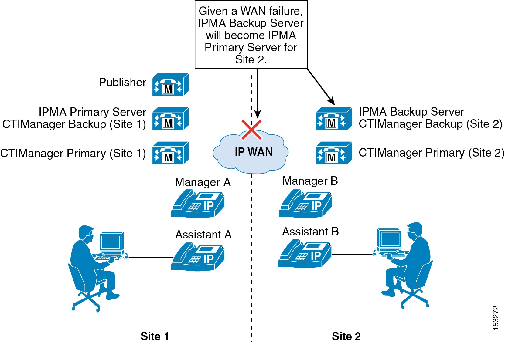
As previously mentioned, the publisher is a single point of failure when it comes to writing Unified CM Assistant information to the Unified CM database. Given a publisher failure, all aspects of the Unified CM Assistant application will continue to work; however, no changes to the Unified CM Assistant application configuration can be made. Configuration changes via the Unified CM Assistant Console desktop application, the Manager configuration web-based application, the phone softkeys, or the Unified CM Assistant phone service, will not be possible until the publisher is restored. This condition includes enabling or disabling features such as Do Not Disturb, DivertAll, Assistant Watch, and call filtering, as well as changing call filter and assistant selection configuration.
Device and Reachability Redundancy
Redundancy for Unified CM Assistant at the devices level relies on a number of mechanisms. First and foremost, manager and assistant phones as well as the Unified CM Assistant RP rely on the built-in redundancy provided by a combination of the device pool and Unified CM group configuration for device registration.
In addition, some devices rely on component services for additional redundancy and functionality. For example, the Unified CM Assistant RP also relies on CTIManager for call control functionality and therefore must rely on the primary and back CTIManager mechanism described in the previous section. The Unified CM Assistant Console desktop application also relies on the component services for redundancy and functionality. The Assistant Console desktop application supports automatic failover from the primary to the backup Unified CM Assistant server (and vice versa) in order to continue to handle incoming calls for managers. The amount of time this automatic failover will take can be controlled using the Cisco IPMA Assistant Console Heartbeat Interval and the Cisco IPMA Assistant Console Request Timeout service parameters. Although the heartbeat or keep-alive frequency can be configured so that failures of the Unified CM Assistant server are detected by the desktop application more quickly, be careful not to affect the network adversely by sending keep-alives too frequently. This consideration is especially important if there are a large number of Assistant Console desktop applications in use.
The Unified CM Assistant Console phone service, unlike the Unified CM Assistant Console desktop application, requires manual intervention for redundancy given the failure of the primary Unified CM Assistant server. If the primary Unified CM Assistant server goes down, assistants using the phone console will not see an indication of this condition. However, the assistant phone will receive a "Host not found Exception" message upon trying to use a softkey. In order to continue using the phone console with the backup Unified CM Assistant server, the user must manually select the secondary Unified CM Assistant phone service from the IP Services menu and log in again.
There are several other failover mechanisms which ensure that Manager and Assistant reachability are redundant. First, calls sent to a Manager's Assistant via the Unified CM Assistant application (in proxy line mode) can be forwarded to the Manager's next available Assistant if the call is not answered after a configured amount of time. If the next Assistant does not answer the call after the configured amount of time, the call can again be forwarded to the Manager's next available Assistant, and so on. The mechanism is configured using the Cisco IPMA RNA Forward Calls and Cisco IPMA RNA Timeout service parameters. Second, as mentioned previously, if all Cisco IP Manager Assistant and CTI services on cluster nodes fail, the Unified CM Assistant RP will become unavailable. However, based on the CFNA configuration of the Unified CM Assistant RP, calls to all Manager DNs will fall-through directly to the Manager phones so that Manager reachability is sufficiently redundant.
Capacity Planning for Unified CM Assistant
The Cisco Unified CM Assistant application supports the following capacities:
•![]() A maximum of 10 Assistants can be configured per Manager.
A maximum of 10 Assistants can be configured per Manager.
•![]() A maximum of 33 Managers can be configured for a single Assistant (if each Manager has one Unified CM Assistant-controlled line).
A maximum of 33 Managers can be configured for a single Assistant (if each Manager has one Unified CM Assistant-controlled line).
•![]() A maximum of 3500 Assistants and 3500 Managers (7000 total users) can be configured per cluster using the Cisco MCS 7845 server or OVA equivalent.
A maximum of 3500 Assistants and 3500 Managers (7000 total users) can be configured per cluster using the Cisco MCS 7845 server or OVA equivalent.
•![]() A maximum of three pairs of primary and backup Unified CM Assistant servers can be deployed per cluster if the Enable Multiple Active Mode advanced service parameter is set to True and a second and third pool of Unified CM Assistant servers are configured.
A maximum of three pairs of primary and backup Unified CM Assistant servers can be deployed per cluster if the Enable Multiple Active Mode advanced service parameter is set to True and a second and third pool of Unified CM Assistant servers are configured.
In order to achieve the maximum Unified CM Assistant user capacity of 3500 Managers and 3500 Assistants (7000 users total), multiple Unified CM Assistant server pools must be defined. As illustrated in Figure 19-11, up to three pools can be configured. Each pool consists of a primary and backup Unified CM Assistant server and a group of Managers and Assistants. Pool 1's Unified CM Assistant servers are configured with the Cisco IPMA Server (Primary/Backup) IP Address service parameters, Pool 2's servers are configured with the Pool2: Cisco IPMA Server (Primary/Backup) IP Address advanced service parameters, and Pool 3's servers are configured with the Pool3: Cisco IPMA Server (Primary/Backup) IP Address advanced service parameters.
Figure 19-11 Multiple Active Mode with Unified CM Assistant Server Pools
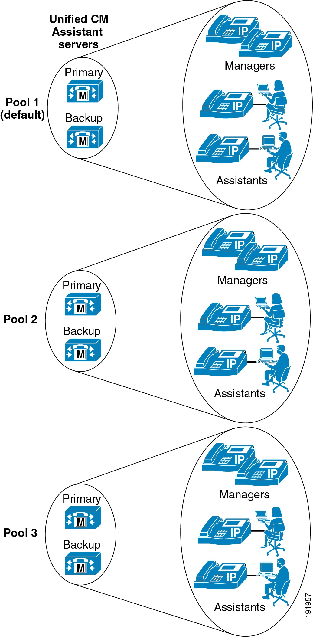
The Cisco Unified CM Assistant application interacts with the CTIManager for line monitoring and phone control. Each line (including Intercom lines) on a Unified CM Assistant or Manager phone requires a CTI line from the CTIManager. In addition, each Unified CM Assistant route point requires a CTI line instance from the CTIManager. When you configure Unified CM Assistant, the number of required CTI lines or connections must be considered with regard to the overall cluster limit for CTI lines or connections. (For more information on CTI connection limits per cluster, see Capacity Planning for CTI.) If additional CTI lines are required for other applications, they can limit the capacity of Unified CM Assistant.
Design Considerations for Unified CM Assistant
Unified CM Assistant has the following limitations with regard to overlapping and shared extensions, which you should keep in mind when planning directory number provisioning:
•![]() With Unified CM Assistant in proxy line mode, the proxy line number(s) on the assistant phone should be unique, even across different partitions.
With Unified CM Assistant in proxy line mode, the proxy line number(s) on the assistant phone should be unique, even across different partitions.
•![]() With Unified CM Assistant in proxy line mode, two Managers cannot have the same Unified CM Assistant controlled line number (DN), even across different partitions.
With Unified CM Assistant in proxy line mode, two Managers cannot have the same Unified CM Assistant controlled line number (DN), even across different partitions.
When enabling Multiple Active Mode and using more than one Unified CM Assistant server pool, ensure that the appropriate server pool (1 to 3) is selected in the Assistant Pool field under the end user Manager Configuration page so that Managers and Assistants are evenly distributed between the Unified CM Assistant server pools. A Manager's associated Assistant will automatically be assigned to the pool where their Manager is configured.
Unified CM Assistant supports a non-secure or secure connection (Transport Layer Security) to the CTI Manager.
Unified CM Assistant Extension Mobility Considerations
Unified CM Assistant Managers can use Extension Mobility (EM) to log in to their phones in both proxy-line and shared-lined modes. However, the Manager must be configured as a Mobile Manager under the Cisco Unified CM Assistant Manager configuration page of the End-user Directory. When using EM in conjunction with Unified CM Assistant, users should not be able to log in to more than one phone using EM. This behavior can be enabled/disabled via the EM service parameter Multiple Login Behavior. If multiple EM logins by the same user are required within the cluster, Unified CM Assistant Managers who use EM should be instructed not to log in to multiple phones. Allowing a manager to log in to two different phones with EM violates the previously stated restriction that, in proxy line mode, two Managers cannot have the same Unified CM Assistant controlled line number (DN), even across different partitions.
Note ![]() Unified CM Assistants cannot use EM to log in to their phones because there is no concept of a Mobile Assistant.
Unified CM Assistants cannot use EM to log in to their phones because there is no concept of a Mobile Assistant.
Unified CM Assistant Dial Plan Considerations
Dial plan configuration is extremely important for Unified CM Assistant configured in proxy line mode. To ensure that calls to Manager DNs are intercepted by the Unified CM Assistant RP and redirected to the Assistant phone, calling search spaces and partitions must be configured in such a way that Manager DNs are unreachable from all devices except the Unified CM Assistant RP and the Manager's proxy line on the Assistant phone.
Figure 19-12 shows an example of a proxy line mode Unified CM Assistant dial plan with the minimum requirements for calling search spaces, partitions, and the configuration of various types of devices within these dial plan components. Three partitions are required for proxy line mode, and for the example in Figure 19-12 they are as follows:
•![]() Assistant_Route_Point partition, containing all the Unified CM Assistant RP DNs
Assistant_Route_Point partition, containing all the Unified CM Assistant RP DNs
•![]() Assistant_Everyone partition, containing all the Assistant and other user phone DNs
Assistant_Everyone partition, containing all the Assistant and other user phone DNs
•![]() Assistant_Manager partition, containing all the Manager phone DNs
Assistant_Manager partition, containing all the Manager phone DNs
In addition, two calling search spaces are required, and for the example in Figure 19-12 they are as follows:
•![]() ASSISTANT_EVERYONE_CSS calling search space, containing both the Assistant_Route_Point and Assistant_Everyone partitions.
ASSISTANT_EVERYONE_CSS calling search space, containing both the Assistant_Route_Point and Assistant_Everyone partitions.
•![]() MANAGER_EVERYONE_CSS calling search space, containing both the Assistant_Manager and Assistant_Everyone partitions.
MANAGER_EVERYONE_CSS calling search space, containing both the Assistant_Manager and Assistant_Everyone partitions.
That is the extent of the dial plan for this example. However, it is also important to properly configure the various phone and Unified CM Assistant RP DNs or lines with the appropriate calling search spaces so that call routing works as required. In this case all user, Assistant primary (or personal), and Manager phone lines would be configured with the ASSISTANT_EVERYONE_CSS calling search space so that all of these lines can reach all the DNs in the Assistant_Everyone and Assistant_Route_Point partitions. Intercom lines and any other lines configured on devices within the telephony network would be configured with this same calling search space. All Manager proxy lines and all Assistant_RP lines are configured with the MANAGER_EVERYONE_CSS calling search space so that all of these lines can reach the Manager DNs in the Assistant_Manager partition as well as all the DNs belonging to the Assistant_Everyone partition. In this way, the dial plan ensures that only the Assistant_RP lines and the Manager proxy lines on the Assistant phones are capable of reaching the Manager phone DNs directly.
Figure 19-12 Unified CM Assistant Proxy Line Mode Dial Plan Example
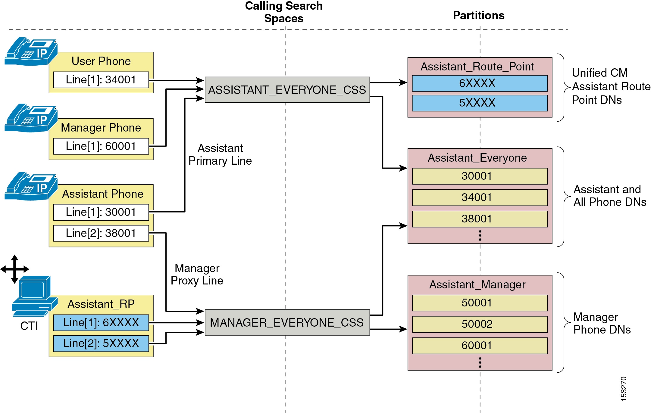
The example in Figure 19-12 shows the minimum dial plan requirements for Unified CM Assistant in proxy line mode. However, most real-world telephony networks will have additional or existing dial plan requirements that must be integrated with the Unified CM Assistant calling search spaces and partitions. Figure 19-13 illustrates such an integration dial plan. In this example, the previously discussed dial plan must now handle two additional partitions and an additional calling search space. The On Cluster partition has been added in Figure 19-13, and it contains some additional phone DNs. The On Cluster partition has been added to both of the existing Unified CM Assistant calling search spaces (ASSISTANT_EVERYONE_CSS and MANAGER_EVERYONE_CSS) so that existing devices can reach these added DNs. The UNRESTRICTED_CSS calling search space has also been added to the existing dial plan. This calling search space is configured with the Assistant_Route_Point, Assistant_Everyone, and the recently added On Cluster partitions. In addition, a second new partition called PSTN has been added, and it contains a set of route patterns used for routing calls to the PSTN via the common route list (RL), route group (RG), and voice gateway mechanism. This PSTN partition is configured as part of the UNRESTRICTED_CSS calling search space.
Phone and device line calling search space configurations may be adjusted to incorporate the newly added partitions and calling search spaces, provided the Assistant_RP and Assistant phone Manager proxy lines remain assigned to the MANAGER_EVERYONE_CSS calling search space. In this example, the Manager phone line has been moved from the originally configured ASSISTANT_EVERYONE_CSS calling search space to the new UNRESTRICTED_CSS because it is likely that a Manager would be given unrestricted access to the PSTN.
Figure 19-13 Unified CM Assistant Proxy Line Mode Dial Plan Integration Example

As Figure 19-13 illustrates, integrating additional partitions and calling search spaces into a new or existing Unified CM Assistant dial plan is feasible, but care must be taken to ensure that the underlying proxy line mode mechanism remains intact.
For Unified CM Assistant shared line mode, no special dial plan provisioning is required. Manager and Assistant phones can be configured with calling search spaces and partitions like any other phones in the network because there are no Unified CM Assistant RPs or proxy lines to be concerned about. The only requirement with regard to shared line mode is that the Manager and Assistant DNs must be in the same partition so that shared line functionality is possible.
Unified CM Assistant Console
The Unified CM Assistant Console desktop application or the Unified CM Assistant Console phone service is required in order for assistants to handle calls on a manager's behalf. The desktop application provides assistants with a graphical interface for handling calls, while the phone service provides a menu-driven interface for handling calls. Both the desktop application and the IP phone service allow the assistant to configure the Manager phone and environment and monitor line status and availability. In addition, the desktop application provides other functions such as click-to-call speed dialing and directory entries, which can also be performed on the assistant phone using the traditional softkey and menu approach.
Unified CM Assistant Console Installation
The Unified CM Assistant Console desktop application can be installed from the following URL:
https://<Server_IP-Address>:8443/plugins/CiscoUnifiedCallManagerAssistantConsole.exe
(where <Server_IP-Address> is the IP address of any node in the cluster)
The Unified CM Assistant Console phone service does not require any installation. To enable the Assistant's phone as a console, subscribe the phone to the Unified CM Assistant phone service. (This is the same service to which Manager phones must also be subscribed.)
Unified CM Assistant Desktop Console QoS
After installation, and in order to handle calls on a Manager's behalf, the Assistant must log on to the application by providing userID and password (as configured in the End-user directory on Unified CM) and will have to toggle status to "online" by clicking the Go Online icon or menu item. Once the user is logged in and online, the desktop application communicates with the Unified CM Assistant server at TCP port 2912. The application chooses an ephemeral TCP port when sourcing traffic. Because the Unified CM Assistant server on Unified CM interfaces with the desktop application for call control (generation and handling of call flows), traffic sourced from Unified CM on TCP port 2912 is QoS-marked by Unified CM as Differentiated Services Code Point (DSCP) of 24 or Per Hop Behavior (PHB) of CS3. In this way, Unified CM Assistant phone control traffic can be queued throughout the network like all other call signaling traffic.
In order to ensure symmetrical marking and queuing, the Unified CM Assistant Console application traffic destined for Unified CM TCP port 2912 should also be marked as DSCP 24 (PHB CS3) to ensure this traffic is placed in the appropriate call signaling queues along the network path toward Unified CM and the Unified CM Assistant server. The Unified CM Assistant Console application marks all traffic as best-effort. This means that you will have to apply an access control list (ACL) at the switch port level (or somewhere along the network path, preferably as close to the console PC as possible) to remark traffic sent by the application PC destined for Unified CM on TCP port 2912 from DSCP 0 (PHB Best Effort) to DSCP 24 (PHB CS3).
Unified CM Assistant Console Directory Window
The directory window within the Assistant Console desktop application enables an assistant to search for end-users in the Unified CM Directory. Search strings entered into the Name field of the directory window are sent to the Unified CM Assistant server, and searches are generated directly against the Unified CM database. Responses to search queries are then sent back to the desktop application by the Unified CM Assistant server.
While the additional traffic generated by directory searches within the desktop application is nominal, this traffic can be problematic in centralized call processing deployments when one or more Unified CM Assistant console applications are running at remote sites. A directory search resulting in a single entry generates approximately one (1) kilobit of traffic from the Unified CM Assistant server to the desktop application. Fortunately, a maximum of 25 entries can be retrieved per search, meaning that a maximum of approximately 25 kilobits of traffic can be generated for each search made by the desktop application. However, if directory searches are made by multiple Unified CM Assistant Console desktop applications across low-speed WAN links from the Unified CM Assistant server, the potential for congestion, delay, and queuing is increased. In addition, directory retrieval traffic is sourced from Unified CM on TCP port 2912, like all other Unified CM Assistant traffic to the desktop. This means that directory retrieval traffic is also marked with DSCP 24 (PHB CS3) and therefore is queued like call signaling traffic. As a result, directory retrieval could potentially congest, overrun, or delay call control traffic.
Note ![]() If a directory search generates more than 25 entries, the assistant is warned via a dialog box with the message: "Your search returned more than 25 entries. Please refine your search."
If a directory search generates more than 25 entries, the assistant is warned via a dialog box with the message: "Your search returned more than 25 entries. Please refine your search."
Given the potential for network congestion, Cisco recommends that administrators encourage Unified CM Assistant Console users to do the following:
•![]() Limit their use of the directory window search function.
Limit their use of the directory window search function.
•![]() To reduce the number of entries returned, enter as much information as possible in the Name field and avoid wild-card or blank searches when using the feature.
To reduce the number of entries returned, enter as much information as possible in the Name field and avoid wild-card or blank searches when using the feature.
These recommendations are especially important if either of the following conditions is true:
•![]() There are many Unified CM Assistant Assistants within the cluster.
There are many Unified CM Assistant Assistants within the cluster.
•![]() There are many assistants separated from the Unified CM and/or Unified CM Assistant servers by low-speed WAN links.
There are many assistants separated from the Unified CM and/or Unified CM Assistant servers by low-speed WAN links.
Unified CM Assistant Phone Console QoS
In order to handle calls on a Manager's behalf using the Unified CM Assistant Phone Console phone service, the Assistant must log on to the service by providing a userID and PIN (as configured in the End-user directory on Unified CM). Once the user is logged in, the phone console service communicates with Unified CM using HTTPS and SCCP. Call control traffic for Unified CM Assistant call generation and call handling is sent between the phone and Unified CM using SCCP. By default this traffic is marked as Differentiated Services Code Point (DSCP) of 24 or Per Hop Behavior (PHB) of CS3, thus ensuring it is queued throughout the network as call signaling traffic, therefore no additional QoS configuration or marking is required.
WebDialer
WebDialer is a click-to-call application for Unified CM that enables users to place calls easily from their PCs using any supported phone device. There is no requirement for administrators to manage CTI links or build JTAPI or TAPI applications because Cisco WebDialer provides a simplified web application and HTTP or Simple Objects Access Protocol (SOAP) interface for those who want to provide their own user interface and authentication mechanisms. Alternatively, the Click to Call Cisco Unified Communications Widget makes use of the SOAP interface and is currently available for download (login authentication required) at
http://tools.cisco.com/support/downloads/go/Redirect.x?mdfid=278875240
This section examines the following design aspects of the WebDialer feature:
•![]() High Availability for WebDialer
High Availability for WebDialer
•![]() Capacity Planning for WebDialer
Capacity Planning for WebDialer
•![]() Design Considerations for WebDialer
Design Considerations for WebDialer
WebDialer Architecture
The WebDialer application contains two servlets: the WebDialer servlet and the Redirector servlet. Both servlets are enabled when the Cisco WebDialer Web service is activated on a subscriber server. While related, they each serve different functions and can be configured to run simultaneously.
WebDialer Servlet
Figure 19-14 illustrates a simple WebDialer example. In this example, user John Smith launches WebDialer from a web-based or desktop application such as the Click to Call Cisco Unified Communications Widget (step 1). WebDialer responds with a request for login credentials. The user must respond with a valid userID and password as configured in the Unified CM end-user directory. In this case, John Smith submits userID = jsmith and password = cisco (step 2). Next, based on this login, WebDialer responds with the Cisco WebDialer Preferences configuration page, and the user must indicate either "User preferred device" or "Use Extension Mobility" (assuming the user has an EM device profile). In this case, user John Smith selects "User preferred device" and selects the appropriate MAC address (SEP00036BC7B973) and directory number (10001) for his phone from drop-down menus on the configuration page (step 3). Finally, the user is presented with a screen requesting the phone number to be called (this value may already be indicated) and must click Dial. In this case, John Smith enters 10002 and, after clicking Dial, a call is automatically generated from his phone to Phone B at number 10002 (step 4).
Note ![]() If the user has previously logged in to the WebDialer application and a web browser and server cookie are still active, the user will not be prompted to log in again during subsequent requests. The user will be prompted to log in again when the cookie has been cleared at the browser or by a restart of the WebDialer server. Alternatively, the user web browser cookie can be set to expire automatically after a certain number of hours as configured by the User Session Expiry WebDialer service parameter.
If the user has previously logged in to the WebDialer application and a web browser and server cookie are still active, the user will not be prompted to log in again during subsequent requests. The user will be prompted to log in again when the cookie has been cleared at the browser or by a restart of the WebDialer server. Alternatively, the user web browser cookie can be set to expire automatically after a certain number of hours as configured by the User Session Expiry WebDialer service parameter.
Figure 19-14 WebDialer Servlet Operation

Redirector Servlet
The Redirector servlet provides WebDialer functionality in a multi-cluster or distributed call processing environment. This functionality allows the use of a single enterprise-wide web-based WebDialer application between all Unified CM clusters. Figure 19-15 illustrates the basic operation of the Redirector servlet as part of the WebDialer application. In this example, the enterprise has three Unified CM clusters: New York, Chicago, and San Francisco. All three clusters have been configured with a single WebDialer application. The San Francisco cluster has been designated as the Redirector.
Note ![]() If the user has previously logged in to the WebDialer application and a web browser and server cookie are still active, the user will not be prompted to log in again during subsequent requests. Alternatively, the user web browser cookie can be set to expire automatically after a certain number of hours as configured by the User Session Expiry WebDialer service parameter.
If the user has previously logged in to the WebDialer application and a web browser and server cookie are still active, the user will not be prompted to log in again during subsequent requests. Alternatively, the user web browser cookie can be set to expire automatically after a certain number of hours as configured by the User Session Expiry WebDialer service parameter.
The Redirector then broadcasts an isClusterUser HTTPS request to every WebDialer in the enterprise simultaneously (as configured in the List of WebDialers service parameter). In this example, the requests go to the Chicago and New York WebDialer servers (see step 3 in Figure 19-15). Because the New York user is local to the New York cluster, the New York WebDialer responds with a positive response (see step 4 in Figure 19-15). Finally, the New York user is redirected to their local WebDialer server, which will handle the application request (see step 5 in Figure 19-15). The user is not notified of the redirect; however, the URL in the browser address bar will be changed as the user is redirected from the Redirector to the local WebDialer server). In this example, only one Redirector is deployed; but in order to provide redundancy for the Redirector, configure the Redirector on multiple clusters, as discussed in the section on Service and Component Redundancy.
Figure 19-15 Redirector Servlet Operation
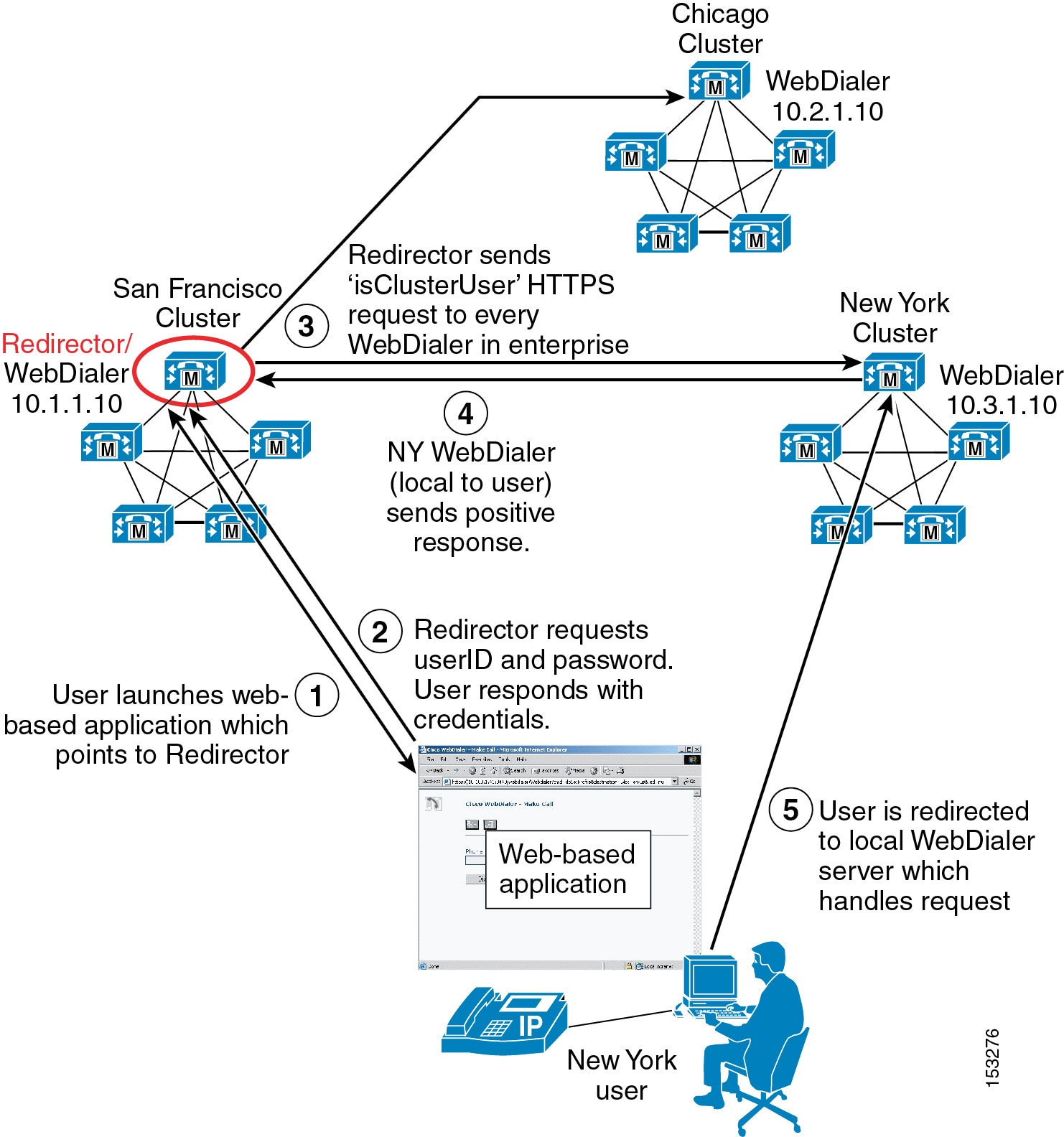
Note ![]() Because the Redirector application is an enterprise-wide application that requires user authentication against the Unified CM Database, Cisco highly recommends that all end-user userIDs be unique across all Unified CM clusters. If they are not, then it is possible that more than one positive response to the isClusterUser request could be received by the Redirector application. If this happens, the user will be asked by the Redirector application to select their local WebDialer server manually. The user will then have to know which server is their local server. If the wrong server is chosen, the WebDialer request will fail.
Because the Redirector application is an enterprise-wide application that requires user authentication against the Unified CM Database, Cisco highly recommends that all end-user userIDs be unique across all Unified CM clusters. If they are not, then it is possible that more than one positive response to the isClusterUser request could be received by the Redirector application. If this happens, the user will be asked by the Redirector application to select their local WebDialer server manually. The user will then have to know which server is their local server. If the wrong server is chosen, the WebDialer request will fail.
WebDialer Architecture
The architecture of the WebDialer application is as important to understand as its functionality. Figure 19-16 depicts the message flows and architecture of WebDialer. The following sequence of interactions and events can occur:
1. ![]() WebDialer user phones register and make and receive calls via the Cisco CallManager service (see step 1 in Figure 19-16).
WebDialer user phones register and make and receive calls via the Cisco CallManager service (see step 1 in Figure 19-16).
2. ![]() The WebDialer application on the user's PC communicates with the Cisco WebDialer Web Service (see step 2 in Figure 19-16) via one of the following interfaces:
The WebDialer application on the user's PC communicates with the Cisco WebDialer Web Service (see step 2 in Figure 19-16) via one of the following interfaces:
–![]() HTML over HTTPS
HTML over HTTPS
This interface is used by web-based applications based on the HTTPS protocol. This is the only interface that provides access to the WebDialer and Redirector servlets.
–![]() Simple Object Access Protocol (SOAP) over HTTPS
Simple Object Access Protocol (SOAP) over HTTPS
This interface is used by desktop applications based on the SOAP interface.
3. ![]() The WebDialer Web service reads user and phone information from the Unified CM Database (see step 3 in Figure 19-16).
The WebDialer Web service reads user and phone information from the Unified CM Database (see step 3 in Figure 19-16).
4. ![]() The WebDialer Web service in turn interacts with the CTIManager service for exchanging line and phone control information (see step 4 in Figure 19-16).
The WebDialer Web service in turn interacts with the CTIManager service for exchanging line and phone control information (see step 4 in Figure 19-16).
5. ![]() The CTIManager service passes WebDialer phone control information to the Cisco CallManager service (see step 5 in Figure 19-16).
The CTIManager service passes WebDialer phone control information to the Cisco CallManager service (see step 5 in Figure 19-16).
Figure 19-16 WebDialer Architecture

Note ![]() Although Figure 19-16 shows the Cisco CallManager, CTIManager, and WebDialer Web Service services all running on the same node, this configuration is not a requirement. These services can be distributed among multiple nodes in the cluster, but they are shown on the same node here for ease of explanation.
Although Figure 19-16 shows the Cisco CallManager, CTIManager, and WebDialer Web Service services all running on the same node, this configuration is not a requirement. These services can be distributed among multiple nodes in the cluster, but they are shown on the same node here for ease of explanation.
WebDialer URLs
The WebDialer application can be accessed from web-based applications via the HTML-over-HTTPS interface using the following URLs:
•![]() WebDialer servlet
WebDialer servlet
https://<Server-IP_Addr>:8443/webdialer/Webdialer?destination=<Number_to_dial>
(where <Server_IP-Address> is the IP address of any node in the cluster running the Cisco WebDialer Web Service service, and where <Number_to_dial> is the number that the WebDialer user wishes to dial)
•![]() Redirector servlet
Redirector servlet
https://<Server-IP_Addr>:8443/webdialer/Redirector?destination=<Number_to_dial>
(where <Server_IP-Address> is the IP address of any node in the enterprise running the Cisco WebDialer Web Service service, and where <Number_to_dial> is the number that the WebDialer user wishes to dial)
Figure 19-17 gives an example of HTML source code used in a click-to-call web-based application calling the Cisco WebDialer application. In this example, the URL https://10.1.1.1:8443/webdialer/Webdialer?destination=30271 in the HTML source view corresponds to the "Phone: 30721" link for user Steve Smith within the web browser view. A user clicking on this link would launch the WebDialer application and, after logging in and clicking Dial, would generate a call from the user's phone to Steve Smith's phone. The same code could be used for a click-to-call application using the Redirector function by changing the URL to https://10.1.1.1:8443/webdialer/Redirector?destination=30271.
Figure 19-17 WebDialer URL HTML Example
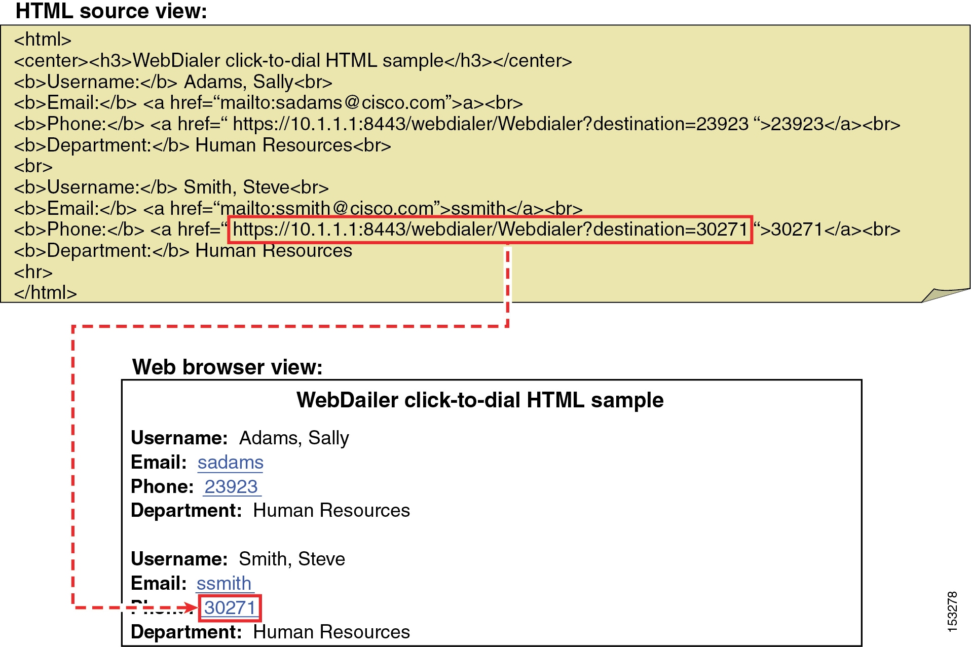
For information and examples of SOAP-over-HTTPS source code to be used in click-to-call desktop applications, refer to the WebDialer API Programming information in the Cisco Unified Communications Manager Developers Guide, available at
http://www.cisco.com/en/US/products/sw/voicesw/ps556/products_programming_reference_guides_list.html
High Availability for WebDialer
WebDialer application redundancy can be provided at two levels:
•![]() Redundancy at the component and service level
Redundancy at the component and service level
At this level, redundancy must be considered with regard to WebDialer and CTIManager service redundancy. Likewise, the lack of publisher redundancy and the impact of this component failing should also be considered.
•![]() Redundancy at the device and reachability level
Redundancy at the device and reachability level
At this level, redundancy should be considered as it relates to user phones and the WebDialer user interface.
Service and Component Redundancy
As shown in Figure 19-16, WebDialer functionality is primarily dependent on the Cisco WebDialer Web Service and the Cisco CTIManager services. The WebDialer service can be enabled on multiple nodes within the cluster. Reachability to those multiple nodes is described in the section on Device and Reachability Redundancy. In the case of CTIManager, redundancy is automatically built-in using a primary and backup mechanism. Two CTIManager servers or services can be defined within the cluster using the Primary Cisco CTIManager and the Backup Cisco CTIManager service parameters. By configuring these parameters, you can make the CTIManager service redundant. Thus, if the primary CTIManager fails, CTIManager services can still be provided by the backup CTIManager. If the WebDialer server to which the web-based (or desktop) application is pointing fails and the primary and backup CTIManager services on cluster nodes also fail, the WebDialer application will fail. The WebDialer service is not dependant upon the Unified CM publisher
Device and Reachability Redundancy
Redundancy for WebDialer at the device level relies on a number of mechanisms. First and foremost, user phones rely on the built-in redundancy provided by a combination of the device pool and Unified CM group configuration for device registration.
The WebDialer service can run on multiple Unified CM subscribers in the same cluster to provide redundancy, however many applications might not be equipped to handle more than one IP address. Cisco recommends using a Server Load Balancer (SLB) to mask the presence of multiple WebDialer servers in the enterprise. SLB functionality provides a virtual IP address or DNS-resolvable hostname that front-ends the real IP addresses of the WebDialer servers. Most SLB devices, such as the Cisco Application Control Engine (ACE) or the Cisco IOS SLB feature, can be configured to monitor the status of multiple WebDialer servers and automatically redirect requests during failure events. The SLB feature can also be configured to load-balance WebDialer requests when additional click-to-call capacity is required. As an alternative, DNS Service (SRV) records can also be used to provide redundancy.
Similarly in a multi-cluster environment, if a single Redirector servlet is supporting multiple WebDialers, it could be a single point of failure. To avoid this single point of failure, configure Redirector servlets for each cluster and use a Server Load Balancer (SLB) to provide a virtual IP address or DNS-resolvable hostname that front-ends the real IP addresses of the Redirector servers.
In enterprise deployments, link cost might also be an important consideration. The Cisco ACE Global Site Selector (GSS) appliance builds upon the capabilities of the SLB feature by adding link cost and location to the load-balancing algorithm, among other features. For more information on ACE and GSS, refer to the product documentation available at http://www.cisco.com.
Capacity Planning for WebDialer
The WebDialer and Redirector services can run on one or more subscriber nodes within a Unified CM cluster, and they support the following capacities:
•![]() Each WebDialer service can handle up to 4 call requests per second per node.
Each WebDialer service can handle up to 4 call requests per second per node.
•![]() Each Redirector service can handle up to 8 call requests per second.
Each Redirector service can handle up to 8 call requests per second.
The following general formula can be used to determine the number of WebDialer calls per second (cps):
(Number of WebDialer users) * ((Average BHCA) / (3600 seconds/hour))
When performing this calculation, it is important to estimate properly the number of BHCA per user that will be initiated specifically from using the WebDialer service. The following example illustrates the use of these WebDialer design calculations for a sample organization.
Example 19-1 Calculating WebDialer Calls per Second
Company XYZ wishes to enable click-to-call applications using the WebDialer service, and their preliminary traffic analysis resulted in the following information:
•![]() 10,000 users will be enabled for click-to-call functionality.
10,000 users will be enabled for click-to-call functionality.
•![]() Each user averages 6 BHCA.
Each user averages 6 BHCA.
•![]() 50% of all calls are dialed outbound, and 50% are received inbound.
50% of all calls are dialed outbound, and 50% are received inbound.
•![]() Projections estimate 30% of all outbound calls will be initiated using the WebDialer service.
Projections estimate 30% of all outbound calls will be initiated using the WebDialer service.
Note ![]() These values are just examples used to illustrate a WebDialer deployment sizing exercise. User dialing characteristics vary widely from organization to organization.
These values are just examples used to illustrate a WebDialer deployment sizing exercise. User dialing characteristics vary widely from organization to organization.
10,000 users each with 6 BHCA equates to a total of 60,000 BHCA. However, WebDialer deployment sizing calculations must account for placed calls only. Given the initial information for this sizing example, we know that 50% of the total BHCA are placed or outbound calls. This results in a total of 30,000 placed BHCA for all the users enabled for click-to-call using WebDialer.
Of these placed calls, the percentage that will be initiated using the WebDialer service will vary from organization to organization. For the organization in this example, several click-to-call applications are made available to the users, and it is projected that 30% of all placed calls will be initiated using WebDialer.
(30,000 placed BHCA) * 0.30 = 9,000 placed BHCA using WebDialer
To determine the number of WebDialer servers required to support a load of 9,000 BHCA, we convert this value to the average call attempts per second required to sustain this busy hour:
(9,000 call attempts / hour) * (hour/3600 seconds) = 2.5 cps
Each WebDialer service can support up to 4 cps, therefore one node should be configured to run the WebDialer service in this example. In order to maintain WebDialer capacity during a server failure, additional backup WebDialer servers should be deployed to provide redundancy.
Keep in mind that the Cisco WebDialer application interacts with the CTIManager for phone control. When enabled, each WebDialer service opens a single persistent CTI connection to the CTIManager. In addition, each WebDialer individual MakeCall (or EndCall) request generates a temporary CTI connection. The number of CTI connections required to handle WebDialer call rates also applies against the CTI connection limits per cluster. (For more information on CTI connection limits per cluster, see Capacity Planning for CTI.)
Design Considerations for WebDialer
The following guidelines and restrictions apply with regard to deployment and operation of WebDialer within the Unified CM telephony environment:
•![]() The administrator should ensure that all WebDialer users are associated with a phone or device profile in the Unified CM end-user directory.
The administrator should ensure that all WebDialer users are associated with a phone or device profile in the Unified CM end-user directory.
–![]() If the user selects "Use permanent device" under the Cisco WebDialer Preferences screen with no phone association, then the following message is received when the Dial button is pressed:
If the user selects "Use permanent device" under the Cisco WebDialer Preferences screen with no phone association, then the following message is received when the Dial button is pressed:
"No supported device configured for user"
–![]() If the user selects Use Extension Mobility under the Cisco WebDialer Preferences screen with no device profile association (or the user is not logged in using a profile), then the following message is received when the Dial button is pressed:
If the user selects Use Extension Mobility under the Cisco WebDialer Preferences screen with no device profile association (or the user is not logged in using a profile), then the following message is received when the Dial button is pressed:
"Call to <dialed_ number> failed: User not logged in on any device"
•![]() An application interfaces with the WebDialer and Redirector servlets through HTTPS.
An application interfaces with the WebDialer and Redirector servlets through HTTPS.
•![]() When using Client Matter Codes (CMC) or Forced Authorization Codes (FAC), WebDialer users must enter the proper code at the tone by using the phone's keypad. Failure to enter the appropriate code at the tone will result in call failure signaled by a reorder tone.
When using Client Matter Codes (CMC) or Forced Authorization Codes (FAC), WebDialer users must enter the proper code at the tone by using the phone's keypad. Failure to enter the appropriate code at the tone will result in call failure signaled by a reorder tone.
•![]() Cisco WebDialer is available on any Cisco endpoints that support Cisco Computer Telephony Integration (CTI). For a list of Cisco endpoints that support Cisco Computer Telephony Integration (CTI), refer to the Cisco CTI Supported Device Matrix, available at
Cisco WebDialer is available on any Cisco endpoints that support Cisco Computer Telephony Integration (CTI). For a list of Cisco endpoints that support Cisco Computer Telephony Integration (CTI), refer to the Cisco CTI Supported Device Matrix, available at
http://developer.cisco.com/web/jtapi/wikidocs/-/wiki/Main/Cisco+CTI+Supported+Device+Matrix
Attendant Consoles
Attendant console integrations enable a receptionist to answer and transfer or dispatch calls within an organization from a desktop application designed specifically for this purpose. Attendant consoles allow for access to the corporate directory and, in some cases, monitoring of line state for specific users. The Cisco Unified Communications portfolio provides the following types of Cisco Unified Attendant Consoles:
•![]() Cisco Unified Attendant Console Department Edition
Cisco Unified Attendant Console Department Edition
•![]() Cisco Unified Attendant Console Business Edition
Cisco Unified Attendant Console Business Edition
•![]() Cisco Unified Attendant Console Enterprise Edition
Cisco Unified Attendant Console Enterprise Edition
•![]() Cisco Unified Attendant Console Premium Edition
Cisco Unified Attendant Console Premium Edition
Cisco Unified Attendant Consoles have a client attendant console application that installs on an attendant's Windows PC. It also requires an attendant console server application installed on a separate physical server than Unified CM. The attendant console application communicates with the attendant console server application, and the attendant console server application communicates with Unified CM securely through CTI and AXL over Secure Socket Layer (SSL). Multiple attendant consoles can connect to a single attendant console server. The Department, Business, Enterprise, and Premium Editions differ in their limits to various capabilities such as the number of supported operator clients and the number of supported directory entries.
This section examines the following design aspects of the attendant consoles:
•![]() Attendant Console Architecture
Attendant Console Architecture
•![]() High Availability for Attendant Consoles
High Availability for Attendant Consoles
•![]() Capacity Planning for Attendant Consoles
Capacity Planning for Attendant Consoles
•![]() Design Considerations for Attendant Consoles
Design Considerations for Attendant Consoles
Attendant Console Architecture
Figure 19-18 illustrates the high-level architecture of a Cisco Unified Attendant Console integration. Understanding the functionality and operation of the solution enhances the understanding of the architecture itself. The following steps (denoted in Figure 19-18) detail the events involved for a typical call into an attendant console.
1. ![]() A call comes into Unified CM, and the called number matches the directory number configured on a CTI route point.
A call comes into Unified CM, and the called number matches the directory number configured on a CTI route point.
2. ![]() The CTI route point is CTI-controlled by the attendant console server application and is associated with a Queue Direct Dial In (DDI) configured on the server.
The CTI route point is CTI-controlled by the attendant console server application and is associated with a Queue Direct Dial In (DDI) configured on the server.
3. ![]() The attendant console server application immediately redirects the call internally to one of its Computer Telephony (CT) Gateway Devices. As part of this process, the attendant console server application sends a CTI redirect message to the CTI Manager service to redirect the call to a CTI port.
The attendant console server application immediately redirects the call internally to one of its Computer Telephony (CT) Gateway Devices. As part of this process, the attendant console server application sends a CTI redirect message to the CTI Manager service to redirect the call to a CTI port.
Note ![]() A CTI redirect message does not result in a connected call; the call is not answered and there is no media connection.
A CTI redirect message does not result in a connected call; the call is not answered and there is no media connection.
4. ![]() The attendant console server application now associates the call with the CT Gateway Device and controls the call on the CTI port.
The attendant console server application now associates the call with the CT Gateway Device and controls the call on the CTI port.
5. ![]() At this point, the call is presented to the attendant console client applications in the system that are associated with the Queue DDI.
At this point, the call is presented to the attendant console client applications in the system that are associated with the Queue DDI.
6. ![]() Once an attendant chooses to answer the call through the attendant console client application, another CTI redirect message is sent to the CTI Manager service, which moves the call from the CTI port to the answering attendant's physical phone. The call is automatically connected on the attendant's phone, either to the handset or the headset, depending on the phone configuration. The region and location settings of the attendant's phone and the initiating gateway or phone dictate the codec used for media.
Once an attendant chooses to answer the call through the attendant console client application, another CTI redirect message is sent to the CTI Manager service, which moves the call from the CTI port to the answering attendant's physical phone. The call is automatically connected on the attendant's phone, either to the handset or the headset, depending on the phone configuration. The region and location settings of the attendant's phone and the initiating gateway or phone dictate the codec used for media.
7. ![]() When a transfer to another extension is required, the attendant initiates the transfer through the attendant console client application, which communicates the transfer to the attendant console server application.
When a transfer to another extension is required, the attendant initiates the transfer through the attendant console client application, which communicates the transfer to the attendant console server application.
8. ![]() The attendant console server application internally associates the call with a Service Queue and sends a CTI redirect message to the CTI Manager service. This redirects the call from the attendant's phone to a CTI port controlled by the attendant console server application.
The attendant console server application internally associates the call with a Service Queue and sends a CTI redirect message to the CTI Manager service. This redirects the call from the attendant's phone to a CTI port controlled by the attendant console server application.
Note ![]() A call transfer may also be initiated from the attendant's phone; however, this would remove the attendant console server application from the call flow, and enhanced functionality (such as the transfer recall feature) would no longer be possible.
A call transfer may also be initiated from the attendant's phone; however, this would remove the attendant console server application from the call flow, and enhanced functionality (such as the transfer recall feature) would no longer be possible.
9. ![]() At this stage, the Service Queue actually answers the call (there is a short connect) before issuing the transfer, therefore the Cisco Media driver installed on the attendant console server application is invoked. The region and location settings of this CTI port and the call-initiating gateway or phone dictate the codec used for media. The configured Music on Hold (MoH) audio sources of the CTI port also affect the MoH heard by the caller. Transfers are performed in this manner so that the attendant console client application still maintains control of the call if there is no answer. Once the call is received by the final party, the attendant console server application is removed from the call flow.
At this stage, the Service Queue actually answers the call (there is a short connect) before issuing the transfer, therefore the Cisco Media driver installed on the attendant console server application is invoked. The region and location settings of this CTI port and the call-initiating gateway or phone dictate the codec used for media. The configured Music on Hold (MoH) audio sources of the CTI port also affect the MoH heard by the caller. Transfers are performed in this manner so that the attendant console client application still maintains control of the call if there is no answer. Once the call is received by the final party, the attendant console server application is removed from the call flow.
Figure 19-18 Architecture for Cisco Unified Department, Business, and Enterprise Attendant Consoles
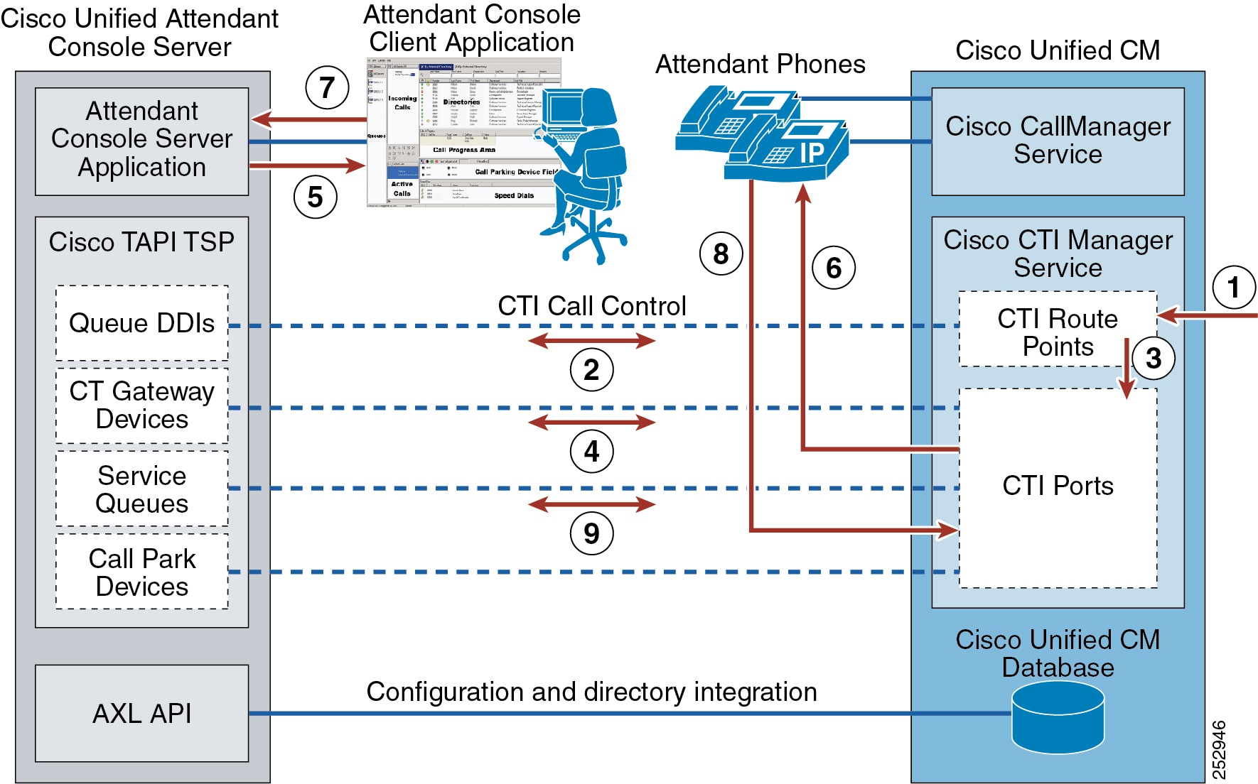
The attendant console server application's call park function does not use the inherent call park feature of Unified CM. Instead, it uses its own call park facility using Call Park Devices. Call Park Devices work very much like the Service Queues as outlined in steps 7 to 9 of Figure 19-18. Similar to transfers, Call Park Devices allow the attendant console server application to maintain control of the call for the duration of the parked call.
High Availability for Attendant Consoles
Cisco Unified Attendant Console Premium Edition can be installed in a resilient configuration with two Cisco Unified Attendant Console servers:
•![]() Publisher — The primary server used by the clients. If this server fails, all attendant operators are switched to the subscriber server. Once the publisher is running again, the operators are prompted to reconnect to the publisher.
Publisher — The primary server used by the clients. If this server fails, all attendant operators are switched to the subscriber server. Once the publisher is running again, the operators are prompted to reconnect to the publisher.
•![]() Subscriber — Used if the publisher stops running for any reason.
Subscriber — Used if the publisher stops running for any reason.
The Cisco Unified Attendant Console Department, Business, and Enterprise Editions are deployed with a single Cisco Unified Attendant Console server.
You should consider providing redundancy on both sides of the integration for both CTI and AXL communication.
Regarding CTI, the attendant console server application uses the Cisco TAPI Telephony Service Provider (TSP) plug-in (downloaded from Unified CM) to communicate with the CTI Manager service. Cisco TSP allows for the configuration of a primary and backup CTI Manager service. Cisco recommends enabling the CTI Manager service on at least two Unified CM subscriber nodes in the cluster to gain resilience in case the primary CTI Manager service goes offline. In the event of an attendant console server failure, resilience can be achieved by configuring a Call Forward Unregistered (CFU) and Call Forward CTI failure destination on all of the CTI route points associated with Queue DDIs. If the attendant console server application is offline, calls will automatically follow the Call Forward setting. For example, with the Cisco Unified Attendant Console Premium Edition, calls can be forwarded to the Cisco Unified Attendant Console subscriber server. With other Cisco Unified Attendant Console Editions, the destination could be a Hunt Pilot number or a Directory Number (DN) associated with a single IP phone.
AXL communication is enabled by activating the Cisco AXL Web Service on a Unified CM node. Multiple Unified CM nodes can have the Cisco AXL Web Service enabled, but the attendant console server application has only a single entry for Unified CM connectivity. In the event of a failure, an administrator could update this entry to a backup Unified CM node running the Cisco AXL Web Service. Cisco Unified Attendant Console Premium Edition has AXL resiliency.
The Unified CM also has a series of CTI route points and CTI ports configured for integration with Cisco Unified Attendant Console. These devices have a device pool and therefore are assigned a Unified CM group, which specifies a prioritized list of the Unified CM call processing nodes responsible for maintaining registration. When the primary Unified CM in the Unified CM group is offline, the CTI route points and CTI ports have the ability to register with a secondary Unified CM node, thus allowing for high availability of the CTI route points and ports themselves.
Capacity Planning for Attendant Consoles
For a comparison of the various Cisco Unified Attendant Console Department, Business, Enterprise, and Premium Editions and their respective capacities, refer to the Cisco Unified Attendant Consoles Business/Department/Enterprise/Premium Edition Design Guide, available at
http://www.cisco.com/en/US/products/ps7282/products_implementation_design_guides_list.html
To size a Unified CM cluster properly, your Cisco Partner or Cisco Systems Engineer should use the Cisco Unified Communications Sizing Tool (http://tools.cisco.com/cucst) to validate all designs that incorporate a large number of CTI resources and high call volumes, because there are many interdependent variables that can affect Unified CM cluster scalability. The Sizing Tool can accurately determine the number of servers or clusters required to meet your Attendant Console design criteria.
For performance and capacity information about the various Cisco Unified Attendant Console Editions, refer to the product documentation available at
http://www.cisco.com/en/US/products/ps7282/tsd_products_support_series_home.html
Design Considerations for Attendant Consoles
The following design guidelines and restrictions apply with regard to the deployment and operation of Cisco Unified Attendant Console within the Unified CM telephony environment.
•![]() The following general design guidance applies to the attendant console server application components:
The following general design guidance applies to the attendant console server application components:
–![]() Queue DDI
Queue DDI
One unique Queue DDI is required for each unique incoming directory number in the system that should be routed specifically to the attendant consoles.
–![]() CT Gateway Device
CT Gateway Device
Every incoming call into a Queue DDI is immediately redirected to a CT Gateway Device. Design the system so that the number of CT Gateway Devices can handle the maximum expected number of incoming calls at any given time.
–![]() Service Queue
Service Queue
Each time an attendant transfers a call or places a call on hold, a Service Queue is required. The system should be designed so that there are enough Service Queues to sustain the maximum number of calls that all attendants in the system are in the process of transferring or putting on hold at any given time. A general guideline is to provide 3 or 4 Service Queues per attendant, but some scenarios might require more.
–![]() Call Park Device
Call Park Device
Each time an attendant invokes the Call Park feature through the attendant console client application, a Call Park Device is required. This feature does not use the inherent Call Park capability of Unified CM. Design the system so that there are sufficient Call Park Devices to handle the maximum number of calls parked by all attendants in the system at any given time.
•![]() Every Queue DDI, CT Gateway Device, Service Queue, and Call Park Device configured in the attendant console server application creates a CTI route point or CTI port in Unified CM. The number of CTI connections required to handle the Unified Department, Business, or Enterprise Attendant Console integration also counts toward the CTI connection limits per cluster. (For more information on CTI connection limits per cluster, see Capacity Planning for CTI.)
Every Queue DDI, CT Gateway Device, Service Queue, and Call Park Device configured in the attendant console server application creates a CTI route point or CTI port in Unified CM. The number of CTI connections required to handle the Unified Department, Business, or Enterprise Attendant Console integration also counts toward the CTI connection limits per cluster. (For more information on CTI connection limits per cluster, see Capacity Planning for CTI.)
•![]() The attendant console server application provides busy lamp field (BLF) monitoring of end-user devices, but it is important to note that this does not use the same facility in Unified CM that provides BLF speed dial capability. Instead, the attendant console server application communicates through CTI with Unified CM to obtain line state information on monitored devices. Once the attendant console server application monitors an end-user device, it continues monitoring this device through CTI until the number of devices monitored for BLF reaches a certain level (2,000). Once this limit is reached, the BLF plug-in begins to drop devices from the list of monitored devices in order to add newly requested devices to the list, thus ensuring that the number of devices monitored by the attendant console server through CTI does not exceed the limit (2,000). These devices monitored through CTI also count toward the CTI limits in Unified CM.
The attendant console server application provides busy lamp field (BLF) monitoring of end-user devices, but it is important to note that this does not use the same facility in Unified CM that provides BLF speed dial capability. Instead, the attendant console server application communicates through CTI with Unified CM to obtain line state information on monitored devices. Once the attendant console server application monitors an end-user device, it continues monitoring this device through CTI until the number of devices monitored for BLF reaches a certain level (2,000). Once this limit is reached, the BLF plug-in begins to drop devices from the list of monitored devices in order to add newly requested devices to the list, thus ensuring that the number of devices monitored by the attendant console server through CTI does not exceed the limit (2,000). These devices monitored through CTI also count toward the CTI limits in Unified CM.
•![]() The attendant console server application provides Busy Lamp Field (BLF) monitoring of end-user devices, but it is important to note that this does not use the same facility in Unified CM that provides BLF speed dial capability. Instead, the attendant console server application communicates through CTI with Unified CM to obtain line state information on monitored devices.
The attendant console server application provides Busy Lamp Field (BLF) monitoring of end-user devices, but it is important to note that this does not use the same facility in Unified CM that provides BLF speed dial capability. Instead, the attendant console server application communicates through CTI with Unified CM to obtain line state information on monitored devices.
•![]() With respect to Quality of Service (QoS), the attendant console server application, the attendant console client application, and the Cisco TSP all send their traffic marked as Best Effort (DSCP=0). If this traffic traverses a WAN or a link that is typically congested, packets must be marked to receive preferential treatment through the network. For a complete list of the TCP port numbers associated with these applications, refer to the Unified Department, Business, or Enterprise Attendant Console design guide, available with appropriate login authentication at
With respect to Quality of Service (QoS), the attendant console server application, the attendant console client application, and the Cisco TSP all send their traffic marked as Best Effort (DSCP=0). If this traffic traverses a WAN or a link that is typically congested, packets must be marked to receive preferential treatment through the network. For a complete list of the TCP port numbers associated with these applications, refer to the Unified Department, Business, or Enterprise Attendant Console design guide, available with appropriate login authentication at
•![]() Cisco TSP is not aware of partitions. Therefore, if the same directory number (DN) exists in multiple partitions, the monitored device might not be the correct DN.
Cisco TSP is not aware of partitions. Therefore, if the same directory number (DN) exists in multiple partitions, the monitored device might not be the correct DN.
•![]() Cisco Unified Attendant Console can also integrate with the Cisco IM and Presence Service through the SIP SIMPLE protocol. For more information about this type of integration, refer to the appropriate Cisco Unified Attendant Console administration guide, available at
Cisco Unified Attendant Console can also integrate with the Cisco IM and Presence Service through the SIP SIMPLE protocol. For more information about this type of integration, refer to the appropriate Cisco Unified Attendant Console administration guide, available at
http://www.cisco.com/en/US/products/ps7282/prod_maintenance_guides_list.html
•![]() For design guidance on Cisco Unified Attendant Consoles, refer to the documentation available at
For design guidance on Cisco Unified Attendant Consoles, refer to the documentation available at
http://www.cisco.com/en/US/products/ps7282/products_implementation_design_guides_list.html
 Feedback