- What's New in This Chapter
- Presence
- Busy Lamp Field (BLF)
- Cisco IM and Presence Architecture
- Cisco IM and Presence Enterprise Instant Messaging
- Cisco IM and Presence Message Archiving and Compliance
- Instant Messaging Storage Requirements
- Cisco IM and Presence Calendar Integration
- Outlook Web Access Calendar Integration
- Exchange Web Services Calendar Integration
- Cisco IM and Presence Mobility Integration
- Cisco IM and Presence Third-Party Open API
- Design Considerations for Cisco IM and Presence
- Third-Party Presence Server Integration
Cisco IM and Presence
Cisco IM and Presence consists of many components that enhance the value of a Cisco Unified Communications system. The main presence component of the solution is the Cisco IM and Presence Service, which incorporates the Jabber Extensible Communications Platform and supports SIP/SIMPLE and Extensible Messaging and Presence Protocol (XMPP) for collecting information regarding a user's availability status and communications capabilities. The user's availability status indicates whether or not the user is actively using a particular communications device such as a phone. The user's communications capabilities indicate the types of communications that user is capable of using, such as video conferencing, web collaboration, instant messaging, or basic audio.
The aggregated user information captured by the Cisco IM and Presence Service enables Cisco Jabber, Cisco Unified Communications Manager applications, and third-party applications to increase user productivity. These applications help connect colleagues more efficiently by determining the most effective form of communication.
This chapter explains the basic concepts of presence and instant messaging within the Cisco Unified Communications System and provides guidelines for how best to deploy the various components of the presence and instant messaging solution. The Cisco IM and Presence Service must be deployed with Cisco Unified Communications Manager (Unified CM) 9.0 or later releases; Cisco Unified CM 8.x and earlier releases interoperate with Cisco Unified Presence.
This chapter covers the following topics:
•![]() Cisco IM and Presence Architecture
Cisco IM and Presence Architecture
•![]() Cisco IM and Presence Enterprise Instant Messaging
Cisco IM and Presence Enterprise Instant Messaging
•![]() Third-Party Presence Server Integration
Third-Party Presence Server Integration
What's New in This Chapter
Table 23-1 lists the topics that are new in this chapter or that have changed significantly from previous releases of this document.
Presence
Presence refers to the ability and willingness of a user to communicate across a set of devices. It involves the following phases or activities:
•![]() Publish user status
Publish user status
User status changes can be published automatically by recognizing user keyboard activity, phone use, or device connectivity to the network.
•![]() Collect this status
Collect this status
The published information is gathered from all the available sources, privacy policies are applied, and then current status is aggregated, synchronized, and stored for consumption.
•![]() Consume the information
Consume the information
Desktop applications, calendar applications, and devices can use the user status information to provide real-time updates for the end users to make better communication decisions.
Status combines the capabilities of what the device or user can do (voice, video, instant messaging, web collaboration, and so forth) and the attributes showing the state of the device or user (available, busy, on a call, and so forth). Presence status can be derived from automatic events such as client login and telephone off-hook, or it can be derived from explicit notification events for changing status such as the user selecting Do Not Disturb from a change-status pick list.
Terminology surrounding presence refers to a watcher, presence entity (presentity), and presence server. The presence entity publishes its current status to the presence server by using a PUBLISH or REGISTER message for SIP/SIMPLE clients, or by using an XML Presence Stanza for XMPP clients. It can be a directory number (DN) or a SIP uniform resource identifier (URI) that resides within or outside the communications cluster. A watcher (device or user) requests presence status about a presence entity by sending a message to the presence server. The presence server responds to the watcher with a message containing the current status of the presence entity.
Cisco IM and Presence Components
Cisco IM and Presence encompasses the following components, illustrated in Figure 23-1:
•![]() Cisco IM and Presence Service
Cisco IM and Presence Service
•![]() Cisco Unified Communications Manager (Unified CM)
Cisco Unified Communications Manager (Unified CM)
•![]() Cisco Jabber
Cisco Jabber
•![]() Cisco Unified MeetingPlace or MeetingPlace Express
Cisco Unified MeetingPlace or MeetingPlace Express
•![]() Cisco Unity or Unity Connection
Cisco Unity or Unity Connection
•![]() Cisco Unified Videoconferencing or Cisco Unified MeetingPlace Express VT
Cisco Unified Videoconferencing or Cisco Unified MeetingPlace Express VT
•![]() Lightweight Directory Access Protocol (LDAP) Server v3.0
Lightweight Directory Access Protocol (LDAP) Server v3.0
•![]() Cisco Unified IP Phones
Cisco Unified IP Phones
•![]() Third-party presence server
Third-party presence server
•![]() Third-party XMPP clients
Third-party XMPP clients
•![]() Third-party applications
Third-party applications
Figure 23-1 Cisco IM and Presence Interfaces

Cisco IM and Presence User
For presence, typically a user is described in terms of the user's presence status, the number of users on the system, or the user's presence capabilities.
As defined by Cisco IM and Presence, a user is specified in Cisco Unified CM by default as an end user and must be configured with a primary extension. The user is effectively tied to a directory number, and the presence status is reflected for the user's primary extension rather than for the device to which the user is associated. (See Figure 23-2.)
A user, specified in Unified CM as an end user, can be configured with a primary extension or associated with a line appearance. When using the CUP PUBLISH Trunk service parameter on Unified CM, you must associate the user with a line appearance rather than just a primary extension. With the line appearance, the user is effectively tied to a line appearance (directory number associated with a particular device), which allows for a more detailed level of granularity for aggregation of presence information. The user can be mapped to multiple line appearances, and each line appearance can have multiple users (up to 5). Cisco recommends associating the end user with a line appearance. (See Figure 23-2.)
A user can also have only IM and Presence capabilities. This deployment requires a Unified CM publisher for configuration, along with an IM and Presence cluster as well as Jabber clients. In this arrangement, telephony voice features would be provided through another vendor's system or PBX.
Figure 23-2 Associating an End User with a Primary Extension or Line Appearance

The concept of a presence user appears throughout this chapter; therefore, keep in mind the meaning of a user as defined for Cisco IM and Presence.
Busy Lamp Field (BLF)
All telephony presence requests for users, whether inside or outside the cluster, are processed and handled by Cisco Unified CM.
A Unified CM watcher that sends a presence request will receive a direct response, including the presence status, if the watcher and presence entity are co-located within the Unified CM cluster.
If the presence entity exists outside the cluster, Unified CM will query the external presence entity through the SIP trunk. If the watcher has permission to monitor the external presence entity based on the SUBSCRIBE calling search space and presence group (both described in the section on Unified CM Presence Policy), the SIP trunk will forward the presence request to the external presence entity, await the presence response from the external presence entity, and return the current presence status to the watcher.
A watcher that is not in a Unified CM cluster can send a presence request to a SIP trunk. If Unified CM supports the presence entity, it will respond with the current presence status. If Unified CM does not support the presence entity, it will reject the presence request with a SIP error response.
Unified CM Presence with SIP
Unified CM uses the term SIP line to represent endpoints supporting SIP that are directly connected and registered to Unified CM and the term SIP trunk to represent trunks supporting SIP. SIP line-side endpoints acting as presence watchers can send a SIP SUBSCRIBE message to Unified CM requesting the presence status of the indicated presence entity.
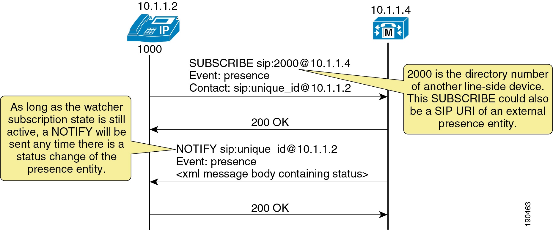
If the presence entity resides within the Unified CM cluster, Unified CM responds to a SIP line-side presence request by sending a SIP NOTIFY message to the presence watcher, indicating the current status of the presence entity. (See Figure 23-3.)
Figure 23-3 SIP Line SUBSCRIBE/NOTIFY Exchange
If the presence entity resides outside the Unified CM cluster, Unified CM routes a SUBSCRIBE request out the appropriate SIP trunk, based on the SUBSCRIBE calling search space, presence group, and SIP route pattern. When Unified CM receives a SIP NOTIFY response on the trunk, indicating the presence entity status, it responds to the SIP line-side presence request by sending a SIP NOTIFY message to the presence watcher, indicating the current status of the presence entity. (See Figure 23-4.)
Figure 23-4 SIP Trunk SUBSCRIBE/NOTIFY Exchange
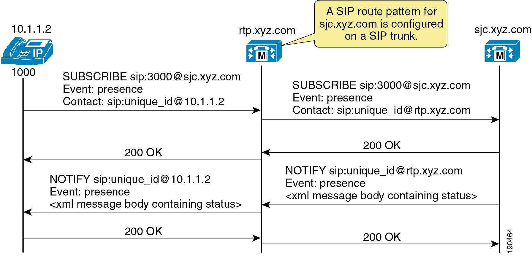
SUBSCRIBE messages for any directory number or SIP URI residing outside the Unified CM cluster are sent or received on a SIP trunk in Unified CM. The SIP trunk could be an interface to another Unified CM or it could be an interface to the Cisco IM and Presence Service.
Unified CM Presence with SCCP
Unified CM supports Skinny Client Control Protocol (SCCP) line-side endpoints acting as presence watchers. There are no SCCP trunks. SCCP endpoints can request presence status of the indicated presence entity by sending SCCP messages to Unified CM.
If the presence entity resides within the Unified CM cluster, Unified CM responds to the SCCP line-side presence request by sending SCCP messages to the presence watcher, indicating the current status of the presence entity.
If the presence entity resides outside the Unified CM cluster, Unified CM routes a SUBSCRIBE request out the appropriate SIP trunk, based on the SUBSCRIBE calling search space, presence group, and SIP route pattern. When Unified CM receives a SIP NOTIFY response on the trunk, indicating the presence entity status, it responds to the SCCP line-side presence request by sending SCCP messages to the presence watcher, indicating the current status of the presence entity.
Unified CM Speed Dial Presence
Unified CM supports the ability for a speed dial to have presence capabilities by means of a busy lamp field (BLF) speed dial. BLF speed dials work as both a speed dial and a presence indicator. However, only the system administrator can configure a BLF speed dial; a system user is not allowed to configure a BLF speed dial.
The administrator must configure the BLF speed dial with a target directory number that is resolvable to a directory number within the Unified CM cluster or a SIP trunk destination. BLF SIP line-side endpoints can also be configured with a SIP URI for the BLF speed dial, but SCCP line-side endpoints cannot be configured with a SIP URI for BLF speed dial. The BLF speed dial indication is a line-level indication and not a device-level indication.
For a listing of the phone models that support BLF speed dials, consult the Cisco Unified IP Phone administration guides available on http://www.cisco.com/.
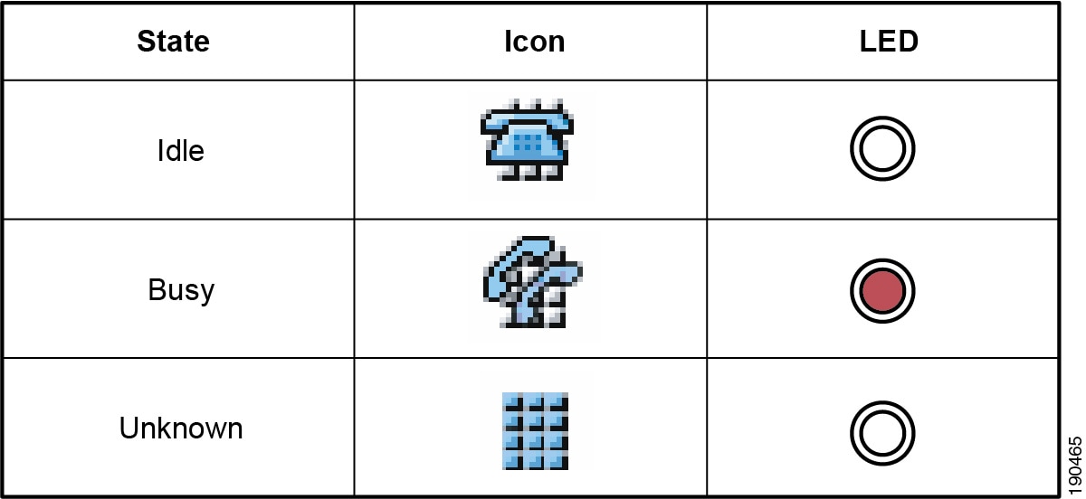
Figure 23-5 lists the various types of BLF speed dial indications from the phones.
Figure 23-5 Indicators for Speed Dial Presence
Unified CM Call History Presence
Unified CM supports presence capabilities for call history lists (the Directories button on the phone). Call history list presence capabilities are controlled via the BLF for Call Lists Enterprise Parameter within Unified CM Administration. The BLF for Call Lists Enterprise Parameter impacts all pages using the phone Directories button (Missed, Received, and Placed Calls, Personal Directory, or Corporate Directory), and it is set on a global basis.
For a listing of the phone models that support presence capabilities for call history lists, consult the Cisco Unified IP Phone administration guides available on http://www.cisco.com/.
The presence indicators for call history lists are the same as those listed in the Icon column in Figure 23-5; however, no LED indications are available.
Unified CM Presence Policy
Unified CM provides the capability to set policy for users who request presence status. You can set this policy by configuring a calling search space specifically to route SIP SUBSCRIBE messages for presence status and by configuring presence groups with which users can be associated to specify rules for viewing the presence status of users associated with another group.
Unified CM Subscribe Calling Search Space
The first aspect of presence policy for Unified CM is the SUBSCRIBE calling search space. Unified CM uses the SUBSCRIBE calling search space to determine how to route presence requests (SUBSCRIBE messages with the Event field set to Presence) that come from the watcher, which could be a phone or a trunk. The SUBSCRIBE calling search space is associated with the watcher and lists the partitions that the watcher is allowed to "see." This mechanism provides an additional level of granularity for the presence SUBSCRIBE requests to be routed independently from the normal call-processing calling search space.
The SUBSCRIBE calling search space can be assigned on a device basis or on a user basis. The user setting applies for originating subscriptions when the user is logged in to the device through Extension Mobility or when the user is administratively assigned to the device.
With the SUBSCRIBE calling search space set to <None>, BLF speed dial and call history list presence status does not work and the subscription messages is rejected as "user unknown." When a valid SUBSCRIBE calling search space is specified, the indicators work and the SUBSCRIBE messages are accepted and routed properly.

Note ![]() Cisco strongly recommends that you do not leave any calling search space defined as <None>. Leaving a calling search space set to <None> can introduce presence status or dialing plan behavior that is difficult to predict.
Cisco strongly recommends that you do not leave any calling search space defined as <None>. Leaving a calling search space set to <None> can introduce presence status or dialing plan behavior that is difficult to predict.
Unified CM Presence Groups
The second aspect of the presence policy for Unified CM is presence groups. Devices, directory numbers, and users can be assigned to a presence group, and by default all users are assigned to the Standard Presence Group. A presence group controls the destinations that a watcher can monitor, based on the user's association with their defined presence group (for example, Contractors watching Executives is disallowed, but Executives watching Contractors is allowed). The presence group user setting applies for originating subscriptions when the user is logged in to the device via Extension Mobility or when the user is administratively assigned to the device.
When multiple presence groups are defined, the Inter-Presence Group Subscribe Policy service parameter is used. If one group has a relationship to another group via the Use System Default setting rather than being allowed or disallowed, this service parameter's value will take effect. If the Inter-Presence Group Subscribe Policy service parameter is set to Disallowed, Unified CM will block the request even if the SUBSCRIBE calling search space allows it. The Inter-Presence Group Subscribe Policy service parameter applies only for presence status with call history lists and is not used for BLF speed dials.
Presence groups can list all associated directory numbers, users, and devices if you enable dependency records. Dependency records allow the administrator to find specific information about group-level settings. However, use caution when enabling the Dependency Record Enterprise parameter because it could lead to high CPU usage.
Unified CM Presence Guidelines
Unified CM enables the system administrator to configure and control user phone state presence capabilities from within Unified CM Administration. Observe the following guidelines when configuring presence within Unified CM:
•![]() Select the appropriate model of Cisco Unified IP Phones that have the ability to display user phone state presence status.
Select the appropriate model of Cisco Unified IP Phones that have the ability to display user phone state presence status.
•![]() Define a presence policy for presence users.
Define a presence policy for presence users.
–![]() Use SUBSCRIBE calling search spaces to control the routing of a watcher presence-based SIP SUBSCRIBE message to the correct destinations.
Use SUBSCRIBE calling search spaces to control the routing of a watcher presence-based SIP SUBSCRIBE message to the correct destinations.
–![]() Use presence groups to define sets of similar users and to define whether presence status updates of other user groups are allowed or disallowed.
Use presence groups to define sets of similar users and to define whether presence status updates of other user groups are allowed or disallowed.
•![]() Call history list presence capabilities are enabled on a global basis; however, user status can be secured by using a presence policy.
Call history list presence capabilities are enabled on a global basis; however, user status can be secured by using a presence policy.
•![]() BLF speed dials are administratively controlled and are not impacted by the presence policy configuration.
BLF speed dials are administratively controlled and are not impacted by the presence policy configuration.
Note ![]() Cisco Business Edition can be used in ways similar to Unified CM to configure and control user presence capabilities. For more information, refer to the chapter on Call Processing.
Cisco Business Edition can be used in ways similar to Unified CM to configure and control user presence capabilities. For more information, refer to the chapter on Call Processing.
Cisco IM and Presence Architecture
The Cisco IM and Presence Service uses standards-based SIP, SIP for Instant Messaging and Presence Leveraging Extensions (SIMPLE), and Extensible Messaging and Presence Protocol (XMPP) to provide a common demarcation point for integrating clients and applications into the Cisco Unified Communications System. Cisco IM and Presence also provides an HTTP interface that has a configuration interface through Simple Object Access Protocol (SOAP); a presence interface through Representational State Transfer (REST); and a presence, instant messaging, and roster interface through the Cisco AJAX XMPP Library (CAXL). The Cisco AJAX XMPP Library interface communicates to the Bidirectional-streams Over Synchronous HTTP (BOSH) interface on the Extensible Communications Platform within Cisco IM and Presence. The Cisco IM and Presence Service collects, aggregates, and distributes user capabilities and attributes using these standards-based SIP, SIMPLE, XMPP, and HTTP interfaces.
Cisco or third-party applications can integrate with presence and provide services that improve the end-user experience and efficiency The core components of the Cisco IM and Presence Service consist of: the Jabber Extensible Communications Platform (XCP), which handles presence, instant messaging, roster, routing, policy, and federation management; the Rich Presence Service, which handles presence state gathering, network-based rich presence composition, and presence-enabled routing functionality; and support for ad-hoc group chat storage with persistent chat and message archiving handled to an external database. If persistent chat is enabled, ad-hoc rooms are stored to the external PostgreSQL database for the duration of the ad-hoc chat. This allows a room owner to escalate an ad-hoc chat to a persistent chat; otherwise, these ad-hoc chats are purged from PostgreSQL at the end of the chat. If persistent chat is disabled, ad-hoc chats are stored in volatile memory for the duration of the chat.
Applications (either Cisco or third-party) can integrate presence and provide services that improve the end user experience and efficiency. In addition, Cisco Jabber is a supported client of the Cisco IM and Presence Service that also integrates instant messaging and presence status.
The Cisco IM and Presence Service also contains support for interoperability with Microsoft Live Communications Server 2005, Microsoft Office Communications Server 2007, and the Microsoft Office Communicator client for any Cisco Unified IP Phone connected to a Unified CM. The Microsoft Office Communicator client interoperability includes click-to-dial functionality, phone control capability, and presence status of Cisco Unified IP Phones.
Cisco IM and Presence Cluster
The Cisco IM and Presence Service uses the same underlying appliance model and hardware used by Unified CM as well as Unified CM on the Cisco Unified Computing System (UCS) platform, including a similar administration interface. For details on the supported platforms, refer to the Cisco Unified Communications Compatibility Tool, available at
http://tools.cisco.com/ITDIT/vtgsca/VTGServlet
A Cisco IM and Presence cluster consists of up to six servers, including one designated as a publisher, which utilize the same architectural concepts as the Unified CM publisher and subscriber. Within a Cisco IM and Presence cluster, individual servers can be grouped to form a subcluster, and the subcluster can have at most two servers associated with it. Figure 23-6 shows the basic topology for a Cisco IM and Presence cluster, while Figure 23-7 shows a highly available topology. The Cisco IM and Presence cluster can also have mixed subclusters, where one subcluster is configured with two servers while other subclusters contain a single server, as shown in Figure 23-8.
Figure 23-6 Basic Deployment of Cisco IM and Presence
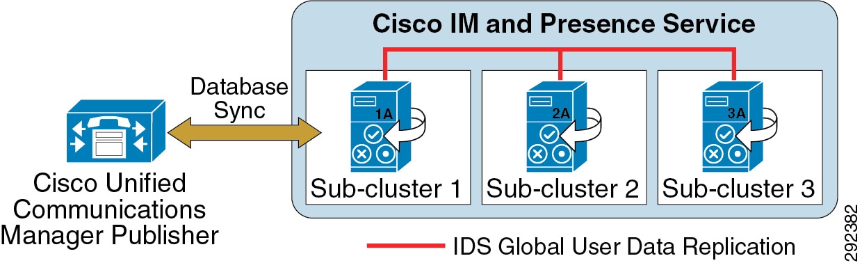
Figure 23-7 High Availability Deployment of Cisco IM and Presence
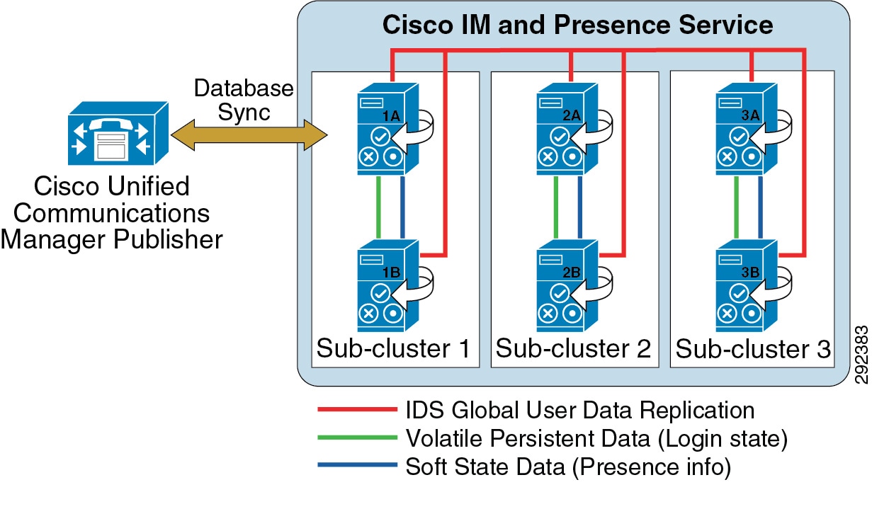
Figure 23-8 Mixed Deployment of Cisco IM and Presence

The Cisco IM and Presence Service utilizes and builds upon the database used by the Unified CM publisher by sharing the user and device information. A Cisco IM and Presence cluster supports only a single Unified CM cluster; therefore, a separate IM and Presence cluster is required for each Unified CM cluster.
Intracluster traffic participates at a very low level between Cisco IM and Presence and Unified CM and between the Cisco IM and Presence publisher and subscriber servers. Both clusters share a common hosts file and have a strong trust relationship using IPTables. At the level of the database and services, the clusters are separate and distinct, and each Cisco IM and Presence Service and Unified CM cluster requires separate administration. There is currently no Transport Layer Security (TLS) or IPSec utilization for intracluster traffic.
The Cisco IM and Presence Service interface with external systems sends SIP and XMPP traffic over UDP, TCP, or TLS. TLS mutual authentication requires the import and export of certificates between Cisco IM and Presence Service and the external system. TLS server authentication (Cisco IM and Presence Service presenting its TLS certificate to the client device for verification) validates the end user via digest authentication.
The Cisco IM and Presence publisher communicates directly with the Unified CM publisher via the AVVID XML Layer Application Program Interface (AXL API) using the Simple Object Access Protocol (SOAP) interface. When first configured, the Cisco IM and Presence publisher performs an initial synchronization of the entire Unified CM user and device database. All Cisco IM and Presence users are configured in the Unified CM End User configuration. During the synchronization, Cisco IM and Presence populates these users in its database from the Unified CM database and does not provide end-user configuration from its administration interface.
The initial Cisco IM and Presence database synchronization from Unified CM might take a while, depending on the amount of information in the database as well as the load that is currently on the system. Subsequent database synchronizations from Unified CM to Cisco IM and Presence are performed in real time when any new user or device information is added to Unified CM. For planning purposes, use the values in Table 23-2 as guidelines when executing the initial database synchronization with Unified CM using a single Cisco IM and Presence publisher.
Note ![]() Cisco IM and Presence supports synchronization of up to 160,000 users, equivalent to Unified CM. However, the maximum number of licensed presence users for a Cisco IM and Presence cluster is 45,000 in full Unified Communications mode and 75,000 in IM-only mode.
Cisco IM and Presence supports synchronization of up to 160,000 users, equivalent to Unified CM. However, the maximum number of licensed presence users for a Cisco IM and Presence cluster is 45,000 in full Unified Communications mode and 75,000 in IM-only mode.
Note ![]() The numbers for the Cisco Unified Computing System (UCS) Open Virtualization Archive (OVA) platforms are equivalent to those for the MCS 7835 (2 vCPU, 4 GB RAM, 80 GB drive, 1 vNIC) and MCS 7845 (4 vCPU, 4 GB RAM, two 80 GB drives, 1 vNIC).
The numbers for the Cisco Unified Computing System (UCS) Open Virtualization Archive (OVA) platforms are equivalent to those for the MCS 7835 (2 vCPU, 4 GB RAM, 80 GB drive, 1 vNIC) and MCS 7845 (4 vCPU, 4 GB RAM, two 80 GB drives, 1 vNIC).
For planning purposes, use the values in Table 23-3 as guidelines when executing the initial database synchronization with Unified CM using a Cisco IM and Presence publisher and subscriber servers:
Note ![]() When the Cisco IM and Presence Service is performing the initial database synchronization from Unified CM, do not perform any administrative activities on Unified CM while the synchronization agent is active.
When the Cisco IM and Presence Service is performing the initial database synchronization from Unified CM, do not perform any administrative activities on Unified CM while the synchronization agent is active.
If the database entries are not updating or if the Sync Agent service is stopped, you can check for broken connections with the synchronization agent by using the Real-Time Monitoring Tool (RTMT) to monitor the Critical Alarm Cisco Unified Presence ServerSyncAgentAXLConnectionFailed.
Cisco IM and Presence Service High Availability
The Cisco IM and Presence cluster consists of up to six servers, which can be configured into multiple subclusters, with a maximum of three subclusters for high availability. A subcluster contains a maximum of two servers and allows for users associated with one server of the subcluster to use the other server in the subcluster automatically if a failover event occurs. Cisco IM and Presence does not provide failover between subclusters.
When deploying a Cisco IM and Presence cluster for high availability, you must take into consideration the maximum number of users per server to avoid oversubscribing any one server within the subcluster in the event of a failover. When deploying a Cisco IM and Presence cluster, use equivalent hardware for all servers within the cluster.
Cisco IM and Presence Deployment Models
Unified CM provides a choice of the following deployment models:
•![]() Single site
Single site
•![]() Multisite WAN with centralized call processing
Multisite WAN with centralized call processing
•![]() Multisite WAN with distributed call processing
Multisite WAN with distributed call processing
•![]() Clustering over the WAN
Clustering over the WAN
Cisco IM and Presence is supported with all the Unified CM deployment models. However, Cisco recommends co-locating the Cisco IM and Presence publisher with the Unified CM publisher due to the initial user database synchronization. All Cisco IM and Presence Services should be co-located within the Cisco IM and Presence cluster, with the exception of geographic datacenter redundancy and clustering over the WAN (for details, see Clustering Over the WAN).
For more information on Unified CM deployment models, see the chapter on Unified Communications Deployment Models.
Cisco IM and Presence deployment depends on high-availability requirements, the total number of users, and the server hardware being used. Cisco recommends using similar hardware for each server in the Cisco IM and Presence cluster. Detailed configuration and deployment steps can be found in the Deployment Guide for Cisco IM and Presence, available at
http://www.cisco.com/en/US/products/ps6837/products_installation_and_configuration_guides_list.html
A highly available Cisco IM and Presence cluster requires two servers per subcluster. This allows for users to fail-over between the servers within the subcluster; however, the total number of users supported and the time to failover vary based on which features are enabled, the average size of contact lists, and the rate of traffic placed on the servers. Once a Cisco IM and Presence subcluster is configured for two servers, it always operates as highly available. High availability can be deployed using an Active/Standby model or an Active/Active model, and these modes are controlled by the Sync Agent service parameter User Assignment Mode. By default all users are balanced across all servers in the cluster, and Cisco recommends leaving this parameter set to its default value.
Cisco IM and Presence Active/Standby mode (setting User Assignment Mode to None) is attained by manually assigning users to the first server in the subcluster, leaving the second server with no users assigned but all processes synchronized and ready for a failover if the first server in the subcluster fails. For example, in Figure 23-7 the first user would be assigned to server 1A, the second user to server 2A, the third user to server 3A, the fourth user to server 1A, the fifth user to server 2A, the sixth user to server 3A, and so forth. The users should be assigned equally across all the 'A' servers in the cluster.
Cisco IM and Presence Active/Active mode (setting User Assignment Mode to balanced) will automatically assign users equally across all servers in the subclusters. Each server is synchronized and ready for a failover if the other server in the subcluster fails. For example, in Figure 23-7 the first user would be assigned to server 1A, the second user to server 2A, the third user to server 3A, the fourth user to server 1B, the fifth user to server 2B, the sixth user to server 3B, and so forth. The users are assigned equally across all the servers in the cluster.
Cisco IM and Presence Active/Active deployments with a balanced User Assignment Mode allows for redundancy flexibility based on the features being used, the size of user contact lists, and the traffic (user data profiles) being generated. A Cisco IM and Presence Active/Active deployment with a fully redundant mode, regardless of features, requires the total number of supported users to be reduced in half (for example, Cisco MCS 7845 servers in a balanced high-availability redundant deployment support up to 15,000 users per subcluster). A Cisco IM and Presence Active/Active deployment with a non-redundant mode requires a more detailed look at the Cisco IM and Presence features being utilized, the average size of the users contact lists, as well as the traffic being generated. For example, for a deployment with presence and instant messaging enabled and calendaring and mobility integration disabled, with an average contact list of 30 users and a user data profile of a few presence and instant message updates, it is possible to support more than 15,000 users per subcluster (if using Cisco MCS 7845 servers).
A Cisco IM and Presence cluster deployment that is not highly available allows for each server in the subcluster to support up to the maximum number of users. Once a second server is added in a subcluster, the subcluster will still act as if in a high-available deployment; however, if a server failure occurs, an attempt to fail-over might not result in success if the online server reaches its capacity limit based on the Cisco IM and Presence features enabled, the average user contact list size, and the traffic being generated by the users.
Cisco IM and Presence Deployment Examples
Example 23-1 Single Unified CM Cluster with Cisco IM and Presence
Deployment requirements:
•![]() 4,000 users that could scale to 13,000 users
4,000 users that could scale to 13,000 users
•![]() Single Cisco Unified Communications Manager cluster
Single Cisco Unified Communications Manager cluster
•![]() Instant message logging and compliance are not needed
Instant message logging and compliance are not needed
•![]() High availability is not needed
High availability is not needed
Hardware:
•![]() Cisco MCS 7845 servers
Cisco MCS 7845 servers
Deployment:
•![]() One single-server subcluster using User Assignment Mode = balanced
One single-server subcluster using User Assignment Mode = balanced
Example 23-2 Two Unified CM Clusters with Cisco IM and Presence
Deployment requirements:
•![]() 11,000 users that could scale to 24,000 users
11,000 users that could scale to 24,000 users
•![]() Two Cisco Unified Communications Manager clusters
Two Cisco Unified Communications Manager clusters
•![]() Instant message logging and compliance are not needed
Instant message logging and compliance are not needed
•![]() High availability is not needed
High availability is not needed
Hardware:
•![]() Cisco MCS 7845 servers
Cisco MCS 7845 servers
Deployment:
•![]() Two Cisco IM and Presence clusters (one per Cisco Unified Communications Manager cluster), each with one server using User Assignment Mode = balanced
Two Cisco IM and Presence clusters (one per Cisco Unified Communications Manager cluster), each with one server using User Assignment Mode = balanced
Example 23-3 Single Unified CM Cluster with Cisco IM and Presence
Deployment requirements:
•![]() 500 users that could scale to 2500 users
500 users that could scale to 2500 users
•![]() Single Cisco Unified Communications Manager cluster
Single Cisco Unified Communications Manager cluster
•![]() Instant message archiving is required
Instant message archiving is required
•![]() High availability is required
High availability is required
Hardware:
•![]() Cisco MCS 7835 servers
Cisco MCS 7835 servers
Deployment:
•![]() One two-server subcluster using User Assignment Mode set to balanced, with a PostgreSQL database instance for the cluster
One two-server subcluster using User Assignment Mode set to balanced, with a PostgreSQL database instance for the cluster
Example 23-4 Single Cisco Business Edition Cluster with Cisco IM and Presence
Deployment requirements:
•![]() 100 users that could scale to 500 users
100 users that could scale to 500 users
•![]() Single Cisco Business Edition
Single Cisco Business Edition
•![]() Instant message archiving and persistent chat are required
Instant message archiving and persistent chat are required
•![]() High availability is required
High availability is required
Hardware:
•![]() Cisco MCS 7825 servers
Cisco MCS 7825 servers
Deployment:
•![]() One two-server subcluster using User Assignment Mode set to balanced, with a unique PostgreSQL database instance per server in the cluster for persistent chat functionality
One two-server subcluster using User Assignment Mode set to balanced, with a unique PostgreSQL database instance per server in the cluster for persistent chat functionality
Example 23-5 Multiple Unified CM Clusters with Cisco IM and Presence
Deployment requirements:
•![]() 5,000 users that could scale to 40,000 users
5,000 users that could scale to 40,000 users
•![]() Multiple Cisco Unified Communications Manager clusters
Multiple Cisco Unified Communications Manager clusters
•![]() Instant message compliance is required
Instant message compliance is required
•![]() High availability is required
High availability is required
Hardware:
•![]() Cisco MCS 7845 servers
Cisco MCS 7845 servers
Deployment:
•![]() Multiple Cisco IM and Presence clusters must be set up with intercluster peers between each. Start with a single two-server subcluster, with up to 15,000 users for each Cisco IM and Presence cluster, before adding more subclusters within existing Cisco IM and Presence clusters. With a large number of users within a single Cisco IM and Presence cluster, set the User Assignment Mode service parameter to balanced. Set up a third-party compliance server for instant messaging compliance for each server in each Cisco IM and Presence cluster.
Multiple Cisco IM and Presence clusters must be set up with intercluster peers between each. Start with a single two-server subcluster, with up to 15,000 users for each Cisco IM and Presence cluster, before adding more subclusters within existing Cisco IM and Presence clusters. With a large number of users within a single Cisco IM and Presence cluster, set the User Assignment Mode service parameter to balanced. Set up a third-party compliance server for instant messaging compliance for each server in each Cisco IM and Presence cluster.
Cisco IM and Presence Deployment for Instant Messaging Only
A Cisco IM and Presence cluster (or clusters) can be deployed to provide enterprise-class presence and instant messaging in an environment where Unified CM is not deployed for call control for specific users. A deployment of IM and Presence only is also referred to as Jabber for Everyone. Unified CM is still required to establish user accounts entered either manually or through LDAP synchronization. A Cisco IM and Presence instant messaging only deployment synchronizes user information from Unified CM in the same way as is done with a full Unified Communications deployment. If Unified CM is not deployed or if the existing deployed Unified CM will not be used for instant messaging only, a Cisco MCS 7816 Media Convergence Server with preloaded Unified CM software is provided as an option.
For existing Cisco IM and Presence deployments where a Unified CM cluster is already deployed, users can also be added for use with the instant messaging only mode. This allows for a mix of full Unified Communications users in addition to instant messaging only users, in accordance with the end-user license agreement.
Cisco IM and Presence Service Performance
Cisco IM and Presence Service clusters support single-server as well as multi-server configurations. However, if multiple servers are used, each server must be on the same type of server platform as the publisher server.
Table 23-4 lists the hardware platform requirements for the Cisco IM and Presence Service as well as the maximum number of users supported per platform. The maximum number of users supported for a Cisco IM and Presence cluster is based on the hardware being used in the deployment. For example, if a Cisco IM and Presence cluster is deployed with three Cisco MCS 7825 servers, each forming their own subcluster, a total of 6,000 users would be supported. The maximum number supported for a Cisco IM and Presence cluster is 45,000 users.
For additional hardware specifications, refer to the Media Convergence Server documentation available at
http://www.cisco.com/en/US/products/hw/voiceapp/ps378/prod_models_home.html
Cisco IM and Presence Deployment
Cisco IM and Presence can be deployed in any of the following configurations:
•![]() Instant Messaging Only Deployment
Instant Messaging Only Deployment
Single-Cluster Deployment
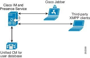
Figure 23-9 represents the communication protocols between Cisco IM and Presence, the LDAP server, and Cisco Unified Communications Manager for basic functionality. For complete information on Cisco IM and Presence administration and configuration, refer to the Cisco IM and Presence installation, administration, and configuration guides, available at
http://www.cisco.com/en/US/products/ps6837/tsd_products_support_series_home.html
Figure 23-9 Interactions Between Cisco IM and Presence Components

Figure 23-9 depicts the following interactions between Cisco IM and Presence components:
1. ![]() The SIP connection between the Cisco IM and Presence Service and Unified CM handles all the phone state presence information exchange.
The SIP connection between the Cisco IM and Presence Service and Unified CM handles all the phone state presence information exchange.
a. ![]() Unified CM configuration requires the Cisco IM and Presence Services to be added as application servers on Unified CM and also requires a SIP trunk pointing to the Cisco IM and Presence Service. The address configured on the SIP trunk could be a Domain Name System (DNS) server (SRV) fully qualified domain name (FQDN) that resolves to the Cisco IM and Presence Services, or it could simply be an IP address of an individual Cisco IM and Presence Service. The Cisco IM and Presence Service handles the configuration of the Cisco Unified Communications Manager application server entry automatically through AXL/SOAP once the administrator adds a node in the system topology page through Cisco IM and Presence administration.
Unified CM configuration requires the Cisco IM and Presence Services to be added as application servers on Unified CM and also requires a SIP trunk pointing to the Cisco IM and Presence Service. The address configured on the SIP trunk could be a Domain Name System (DNS) server (SRV) fully qualified domain name (FQDN) that resolves to the Cisco IM and Presence Services, or it could simply be an IP address of an individual Cisco IM and Presence Service. The Cisco IM and Presence Service handles the configuration of the Cisco Unified Communications Manager application server entry automatically through AXL/SOAP once the administrator adds a node in the system topology page through Cisco IM and Presence administration.
b. ![]() Configuration of Cisco IM and Presence occurs through the Unified CM Presence Gateway for presence information exchange with Unified CM. The following information is configured:
Configuration of Cisco IM and Presence occurs through the Unified CM Presence Gateway for presence information exchange with Unified CM. The following information is configured:
Presence Gateway: server_fqdn:5070
Note ![]() The server_fqdn could be the FQDN of the Unified CM publisher, a DNS SRV FQDN that resolves to the Unified CM subscriber servers, or an IP address.
The server_fqdn could be the FQDN of the Unified CM publisher, a DNS SRV FQDN that resolves to the Unified CM subscriber servers, or an IP address.
If DNS is highly available within your network and DNS SRV is an option, configure the SIP trunk on Unified CM with a DNS SRV FQDN of the Cisco IM and Presence publisher and subscriber. Also configure the Presence Gateway on the Cisco IM and Presence Service with a DNS SRV FQDN of the Unified CM subscribers, equally weighted. This configuration will allow for presence messaging to be shared equally among all the servers used for presence information exchange.
If DNS is not highly available or not a viable option within your network, use IP addressing. When using an IP address, presence messaging traffic cannot be equally shared across multiple Unified CM subscribers because it points to a single subscriber.
Unified CM provides the ability to further streamline communications and reduce bandwidth utilization by means of the service parameter CUP PUBLISH Trunk, which allows for the PUBLISH method (rather than SUBSCRIBE/NOTIFY) to be configured and used on the SIP trunk interface to Cisco IM and Presence. Once the CUP PUBLISH Trunk service parameter has been enabled, the users must be associated with a line appearance and not just a primary extension.
2. ![]() The Computer Telephony Integration Quick Buffer Encoding (CTI-QBE) connection between Cisco IM and Presence and Unified CM is the protocol used by presence-enabled users in Cisco IM and Presence to control their associated phones registered to Unified CM. This CTI communication occurs when Cisco Jabber is using Desk Phone mode to do Click to Call or when Microsoft Office Communicator is doing Click to Call through Microsoft Live Communications Server 2005 or Office Communications Server 2007 or Microsoft Lync.
The Computer Telephony Integration Quick Buffer Encoding (CTI-QBE) connection between Cisco IM and Presence and Unified CM is the protocol used by presence-enabled users in Cisco IM and Presence to control their associated phones registered to Unified CM. This CTI communication occurs when Cisco Jabber is using Desk Phone mode to do Click to Call or when Microsoft Office Communicator is doing Click to Call through Microsoft Live Communications Server 2005 or Office Communications Server 2007 or Microsoft Lync.
a. ![]() Unified CM configuration requires the user to be associated with a CTI Enabled Group, and the primary extension assigned to that user must be enabled for CTI control (checkbox on the Directory Number page). The CTI Manager Service must also be activated on each of the Unified CM subscribers used for communication with the Cisco IM and Presence publisher and subscriber. Integration with Microsoft Live Communications Server 2005 or Office Communications Server 2007 or Microsoft Lync requires that you configure an Application User, with CTI Enabled Group and Role, on Unified CM.
Unified CM configuration requires the user to be associated with a CTI Enabled Group, and the primary extension assigned to that user must be enabled for CTI control (checkbox on the Directory Number page). The CTI Manager Service must also be activated on each of the Unified CM subscribers used for communication with the Cisco IM and Presence publisher and subscriber. Integration with Microsoft Live Communications Server 2005 or Office Communications Server 2007 or Microsoft Lync requires that you configure an Application User, with CTI Enabled Group and Role, on Unified CM.
b. ![]() Cisco IM and Presence CTI configuration (CTI Server and Profile) for use with Cisco Jabber is automatically created during the database synchronization with Unified CM. All Cisco Jabber CTI communication occurs directly with Unified CM and not through the Cisco IM and Presence Service.
Cisco IM and Presence CTI configuration (CTI Server and Profile) for use with Cisco Jabber is automatically created during the database synchronization with Unified CM. All Cisco Jabber CTI communication occurs directly with Unified CM and not through the Cisco IM and Presence Service.
Cisco IM and Presence CTI configuration (Desktop Control Gateway) for use with Microsoft Live Communications Server 2005 or Office Communications Server 2007 or Microsoft Lync requires you to set the Desktop Control Gateway address (Cisco Unified Communications Manager Address) and a provider, which is the application user configured previously in Unified CM. Up to eight Cisco Unified Communications Manager Addresses can be provisioned for increased scalability. Only IP addresses can be used for Desktop Control Gateway configuration in the Cisco IM and Presence Service. Administrators should ensure that any configuration and assignment of Cisco Unified Communications Manager addresses is evenly distributed for the purpose of load balancing.
3. ![]() The AXL/SOAP interface handles the database synchronization from Unified CM to populate the Cisco IM and Presence database.
The AXL/SOAP interface handles the database synchronization from Unified CM to populate the Cisco IM and Presence database.
a. ![]() No additional configuration is required on Unified CM.
No additional configuration is required on Unified CM.
b. ![]() Cisco IM and Presence security configuration requires you to set a user and password for the Unified CM AXL account in the AXL configuration.
Cisco IM and Presence security configuration requires you to set a user and password for the Unified CM AXL account in the AXL configuration.
The Sync Agent Service Parameter, User Assignment, set to balanced by default, will load-balance all users equally across all servers within the Cisco IM and Presence cluster. The administrator can also manually assign users to a particular server in the Cisco IM and Presence cluster by changing the User Assignment service parameter to None.
4. ![]() The LDAP interface is used for LDAP authentication of Cisco Jabber users during login. For more information regarding LDAP synchronization and authentication, see the chapter on LDAP Directory Integration.
The LDAP interface is used for LDAP authentication of Cisco Jabber users during login. For more information regarding LDAP synchronization and authentication, see the chapter on LDAP Directory Integration.
Unified CM is responsible for all user entries via manual configuration or synchronization directly from LDAP, and Cisco IM and Presence then synchronizes all the user information from Unified CM. If a Cisco Jabber user logs into the Cisco IM and Presence Service and LDAP authentication is enabled on Unified CM, Cisco IM and Presence will go directly to LDAP for the Cisco Jabber user authentication using the Bind operation. Once Cisco Jabber is authenticated, Cisco IM and Presence forwards the information to Cisco Jabber to continue login.
When using Microsoft Active Directory, consider the choice of parameters carefully. Performance of Cisco IM and Presence might be unacceptable when a large Active Directory implementation exists and the configuration uses a Domain Controller. To improve the response time of Active Directory, it might be necessary to promote the Domain Controller to a Global Catalog and configure the LDAP port as 3268.
Multi-Cluster Deployment
The deployment topology in previous sections is for a single Cisco IM and Presence cluster communicating with a single Unified CM cluster. Presence and instant messaging functionality is limited by having communications within a single cluster only. Therefore, to extend presence and instant messaging capability and functionality, these standalone clusters can be configured for peer relationships for communication between clusters within the same domain. This functionality provides the ability for users in one cluster to communicate and subscribe to the presence of users in a different cluster within the same domain.
To create a fully meshed presence topology, each Cisco IM and Presence cluster requires a separate peer relationship for each of the other Cisco IM and Presence clusters within the same domain. The address configured in this intercluster peer could be a DNS SRV FQDN that resolves to the remote Cisco IM and Presence cluster servers, or it could also simply be the IP address of the Cisco IM and Presence cluster servers.
The interface between each Cisco IM and Presence cluster is two-fold, an AXL/SOAP interface and a signaling protocol interface (SIP or XMPP). The AXL/SOAP interface handles the synchronization of user information for home cluster association, but it is not a full user synchronization. The signaling protocol interface (SIP or XMPP) handles the subscription and notification traffic, and it rewrites the host portion of the URI before forwarding if the user is detected to be on a remote Cisco IM and Presence cluster within the same domain.
When Cisco IM and Presence is deployed in a multi-cluster environment, a presence user profile should be determined. The presence user profile helps determine the scale and performance of a multi-cluster presence deployment and the number of users that can be supported. The presence user profile helps establish the number of contacts (or buddies) a typical user has, as well as whether those contacts are mostly local cluster users or users of remote clusters.
The traffic generated between Cisco IM and Presence clusters is directly proportional to the characteristics of the presence user profile. For example, assume presence user profile A has 30 contacts with 20% of the users on a local Cisco IM and Presence cluster and 80% of the users on a remote Cisco IM and Presence cluster, while presence user profile B has 30 contacts with 50% of the users on a local Cisco IM and Presence cluster and 50% of the users on a remote Cisco IM and Presence cluster. In this case, presence user profile B will provide for slightly better network performance and less bandwidth utilization due to a smaller amount of remote cluster traffic.
Clustering Over the WAN
A Cisco IM and Presence cluster can be deployed with one of the nodes of a subcluster deployed across the Wide Area Network (WAN). This allows for geographic redundancy of a subcluster and high availability for the users between the nodes across the sites. The following guidelines must be used when planning for a Cisco IM and Presence deployment with clustering over the WAN.
•![]() Geographic datacenter redundancy and remote failover
Geographic datacenter redundancy and remote failover
A Cisco IM and Presence cluster can be deployed between two sites with a single subcluster topology, where one server of the subcluster is in one geographic site and the other server of the subcluster is in another site. This deployment must have a minimum bandwidth of 5 Mbps, a maximum latency of 80 ms round-trip time (RTT), and TCP method event routing.
•![]() High availability and scale
High availability and scale
Cisco IM and Presence high availability allows for users on one node within a subcluster to automatically fail-over to the other node within the subcluster. With a Cisco IM and Presence subcluster containing a maximum of two nodes, remote failover is essentially between two sites, one site for each node. A scalable highly available capacity for a Cisco IM and Presence cluster is up to three subclusters; therefore, a scalable highly available remote failover topology would consist of the following two sites:
–![]() Site A: Subcluster 1 node A, subcluster 2 node A, and subcluster 3 node A
Site A: Subcluster 1 node A, subcluster 2 node A, and subcluster 3 node A
–![]() Site B: Subcluster 1 node B, subcluster 2 node B, and subcluster 3 node B
Site B: Subcluster 1 node B, subcluster 2 node B, and subcluster 3 node B
This deployment must have a minimum bandwidth of 5 Mbps per subcluster, a maximum latency of 80 ms round-trip time (RTT), and TCP method event routing. Each new subcluster added to the deployment requires an additional 5 Mbps of dedicated bandwidth to handle the database and state replication.
•![]() Local Failover
Local Failover
A Cisco IM and Presence cluster deployment between two sites may also contain a subcluster topology per site (single node or dual node for high availability), where one subcluster is in one geographic site and the other subcluster is in another geographic site. This topology allows for the users to remain at their local site (highly available or not) without the requirement or need to fail-over to a different site or location. This deployment must have a minimum bandwidth of 5 Mbps dedicated bandwidth between each subcluster in the respective sites, a maximum latency of 80 ms round-trip time (RTT), and TCP method event routing.
•![]() Bandwidth and latency considerations
Bandwidth and latency considerations
With a Cisco IM and Presence cluster that has a topology of nodes split across a WAN, the number of contacts within a user's client can impact the bandwidth needs and criteria for the deployment. The traffic generated within and between Cisco IM and Presence clusters is directly proportional to the characteristics of the presence user profile, and thus the amount of bandwidth required for deployment. Cisco recommends 25% or fewer remote contacts for a client in environments where the bandwidth is low (10 Mbps or less), and at all times the maximum round-trip latency must be 80 ms or less.
•![]() Persistent Chat and Compliance logging considerations
Persistent Chat and Compliance logging considerations
When Cisco IM and Presence is enabled for persistent chat, message archiving, or compliance logging and a sublcuster is split across a WAN, the external database server(s) must reside on the same side of the WAN as the Cisco IM and Presence Services that use them. With the ability to support multiple database instances on a single server and the requirement for an external database server to reside on the same side of the WAN, if a Cisco IM and Presence cluster is split across a WAN, then two external database servers will be required.
Federated Deployment
Cisco IM and Presence allows for business-to-business communications by enabling inter-domain federation, which provides the ability to share presence and instant messaging communications between different domains. Inter-domain federation requires two explicit DNS domains to be configured, as well as a security appliance (Cisco Adaptive Security Appliance) in the DMZ to terminate federated connections with the enterprise. If all the federated domains are within the same trust boundary, where a deployment has all components within a single datacenter, then the use of the Adaptive Security Appliance is not required. For information on inter-domain federation, refer to the Integration Guide for Configuring Cisco IM and Presence Interdomain Federation, available at
http://www.cisco.com/en/US/products/ps6837/products_installation_and_configuration_guides_list.html
Figure 23-10 shows the basic inter-domain federation deployment between two different domains, indicated by Domain A and Domain B. The Adaptive Security Appliance (ASA) in the DMZ is used as a demarcation into the enterprise. XMPP traffic is passed through, whereas SIP traffic is inspected. All federated incoming and outgoing traffic is routed through the Cisco IM and Presence Service that is enabled as a federation node, and is routed internally to the appropriate server in the cluster where the user resides. For multi-cluster deployments, intercluster peers propagate the traffic to the appropriate home cluster within the domain. Multiple nodes can be enabled as federation nodes within large enterprise deployments, where each request is routed based on a round-robin implementation of the data returned from the DNS SRV lookup.
Figure 23-10 Cisco IM and Presence XMPP Federation (Inter-Domain)

Cisco IM and Presence also provides configuration through SIP to allow for inter-domain federation with Microsoft and AOL, as depicted in Figure 23-11. Cisco IM and Presence inter-domain federation with Microsoft Lync Server, Office Communications Server (OCS), and Live Communications Server (LCS) provides basic presence (available, away, busy, offline) and point-to-point instant messaging. Rich presence capability (On the Phone, In a Meeting, On Vacation, and so forth), as well as advanced instant messaging features, are not supported. Cisco IM and Presence inter-domain federation with AOL allows federation with users of AOL public communities (aim.com, aol.com), with users of domains hosted by AOL, and with users of a far-end enterprise that federates with AOL (that is, AOL is being used as a clearing house).
Note ![]() A SIP federation (inter-domain to AOL) on Cisco IM and Presence must be configured for each domain of the AOL network, which can consist of both hosted networks and public communities. Each unique hosted domain must be configured; however, only a single aol.com public community needs to be configured because the AOL network allows a user to be addressed as user@aol.com or user@aim.com
A SIP federation (inter-domain to AOL) on Cisco IM and Presence must be configured for each domain of the AOL network, which can consist of both hosted networks and public communities. Each unique hosted domain must be configured; however, only a single aol.com public community needs to be configured because the AOL network allows a user to be addressed as user@aol.com or user@aim.com
The inter-domain federation configuration also allows for a specific federation between Cisco IM and Presence and Microsoft Lync Server or Microsoft Office Communications Server (OCS), as depicted in Figure 23-11. Cisco IM and Presence provides inter-domain federation with Microsoft Lync Server, Microsoft Office Communications Server (OCS), or Live Communications Server (LCS) to provide basic presence (available, away, busy, offline) and point-to-point instant messaging. Rich presence capability (On the Phone, In a Meeting, On Vacation, and so forth), as well as advanced instant messaging features, are not supported.
Figure 23-11 Cisco IM and Presence SIP Federation (Inter-Domain)

Table 23-5 lists the state mappings between Cisco IM and Presence and Microsoft Office Communications Server.
Note ![]() Cisco IM and Presence must publish a DNS SRV record (SIP, XMPP, and each text conferencing node) for the domain to allow for other domains to discover the Cisco IM and Presence Services through DNS SRV. With a Microsoft Office Communications Server or Live Communications Server deployment, this is required because Cisco IM and Presence is configured as a Public IM Provider on the Access Edge server. If the Cisco IM and Presence Service cannot discover the Microsoft domain using DNS SRV, you must configure a static route on Cisco IM and Presence for the external domain.
Cisco IM and Presence must publish a DNS SRV record (SIP, XMPP, and each text conferencing node) for the domain to allow for other domains to discover the Cisco IM and Presence Services through DNS SRV. With a Microsoft Office Communications Server or Live Communications Server deployment, this is required because Cisco IM and Presence is configured as a Public IM Provider on the Access Edge server. If the Cisco IM and Presence Service cannot discover the Microsoft domain using DNS SRV, you must configure a static route on Cisco IM and Presence for the external domain.
The Cisco IM and Presence federation deployment can be configured with redundancy using a load balancer between the Adaptive Security Appliance and the Cisco IM and Presence Service, or redundancy can also be achieved with a redundant Adaptive Security Appliance configuration.
Additional configuration and deployment considerations regarding a federated deployment can be found in the latest version of the Integration Guide for Configuring Cisco IM and Presence for Interdomain Federation, available at
http://www.cisco.com/en/US/products/ps6837/products_installation_and_configuration_guides_list.html
An intra-domain partitioned federated deployment, shown in Figure 23-12, is a secondary option that allows for Cisco IM and Presence and Microsoft Live Communications Server 2005 or Office Communications Server 2007 R2 to federate presence and instant messaging within the same presence domain. The users are partitioned across both deployments, within the single presence domain, and are licensed either on Cisco IM and Presence or on the Microsoft Live Communications Server or Office Communications Server. The user cannot be licensed on both the Cisco and Microsoft platforms at the same time.
Figure 23-12 Cisco IM and Presence Intra-Domain Federation

Note ![]() Microsoft Office Communications Server 2007 R1 and Microsoft Lync are not supported in an intra-domain partitioned federated deployment.
Microsoft Office Communications Server 2007 R1 and Microsoft Lync are not supported in an intra-domain partitioned federated deployment.
The partitioned intra-domain federation between the Cisco and Microsoft platforms is based on the SIP/SIMPLE protocol and allows for basic presence and instant messaging exchange, as supported with the Cisco IM and Presence inter-domain federation support for Microsoft Office Communications Server. Rich presence and group chat functionality are not supported with the partitioned intra-domain presence federation.
Inter-domain federation and partitioned intra-domain federation can be supported simultaneously with the following qualifications:
•![]() XMPP federation may be enabled on the Cisco IM and Presence deployment but is available only to Cisco IM and Presence licensed users.
XMPP federation may be enabled on the Cisco IM and Presence deployment but is available only to Cisco IM and Presence licensed users.
•![]() SIP federation may be enabled either on Cisco IM and Presence or on Microsoft Live Communications Server 2005 or Office Communications Server 2007 R2; however, for SIP Federation to be available to both Cisco and Microsoft users, it must be enabled on Microsoft Live Communications Server 2005 or Office Communications Server 2007 R2.
SIP federation may be enabled either on Cisco IM and Presence or on Microsoft Live Communications Server 2005 or Office Communications Server 2007 R2; however, for SIP Federation to be available to both Cisco and Microsoft users, it must be enabled on Microsoft Live Communications Server 2005 or Office Communications Server 2007 R2.
•![]() SIP intercluster trunking with Cisco Unified Presence 7.x is not available with partitioned intra-domain federation.
SIP intercluster trunking with Cisco Unified Presence 7.x is not available with partitioned intra-domain federation.
•![]() If SIP/SIMPLE inter-domain federation with Microsoft Office Communications Server is required in parallel with the partitioned intra-domain federation, then the Microsoft Live Communications Server or Office Communications Server will manage that external federation. Cisco IM and Presence administration must be configured with static routes to the Microsoft environment for the external domain.
If SIP/SIMPLE inter-domain federation with Microsoft Office Communications Server is required in parallel with the partitioned intra-domain federation, then the Microsoft Live Communications Server or Office Communications Server will manage that external federation. Cisco IM and Presence administration must be configured with static routes to the Microsoft environment for the external domain.
Instant Messaging Only Deployment
Cisco IM and Presence allows for an enterprise-class instant messaging only solution, which provides full presence and instant messaging support as defined in the section on Cisco IM and Presence Enterprise Instant Messaging, to be deployed in cases where a full Unified Communications deployment is not yet provided. A Cisco IM and Presence cluster deployed in an instant messaging only environment supports up to three servers in a cluster (see Figure 23-13). Instant messaging only users on Cisco IM and Presence are still provisioned from Unified CM through the AXL/SOAP interface by means of LDAP synchronization or manual provisioning. Cisco Jabber and third-party XMPP clients are the supported clients in a Cisco IM and Presence instant messaging only deployment, and all other design guidelines for Cisco IM and Presence apply.
Figure 23-13 Instant Messaging Only User Mode Deployment
Cisco IM and Presence Migration
Migration from earlier releases of Cisco Unified Presence to Cisco IM and Presence is supported in the following cases (see Figure 23-14):
•![]() Direct migration from Cisco Unified Communications Manager (Unified CM) 7.x or 8.x to Cisco Unified Communications 9.x IM and Presence — provides the ability to deploy Unified CM with voice, video, IM, and presence.
Direct migration from Cisco Unified Communications Manager (Unified CM) 7.x or 8.x to Cisco Unified Communications 9.x IM and Presence — provides the ability to deploy Unified CM with voice, video, IM, and presence.
•![]() Direct migration from Cisco Unified Presence 8.x IM-only to Cisco Unified Communications 9.x IM and Presence — provides the ability to deploy Unified CM with voice, video, IM, and presence.
Direct migration from Cisco Unified Presence 8.x IM-only to Cisco Unified Communications 9.x IM and Presence — provides the ability to deploy Unified CM with voice, video, IM, and presence.
•![]() Direct migration from Unified CM 7.x or 8.x and Cisco Unified Presence 8.x to Cisco Unified Communications 9.x IM and Presence — provides the ability to deploy Unified CM with voice, video, IM, and presence.
Direct migration from Unified CM 7.x or 8.x and Cisco Unified Presence 8.x to Cisco Unified Communications 9.x IM and Presence — provides the ability to deploy Unified CM with voice, video, IM, and presence.
Earlier versions of Unified CM and Cisco Unified Presence require a multi-step upgrade migration.
Figure 23-14 Large Enterprise Migration with Backward Compatibility

Cisco IM and Presence Service Policy
Cisco IM and Presence Service policy is set by the user and not the administrator. A default set of rules, with everything open and available, applies if the user does not make any modifications to the policy rules. All policy configuration control is provided in the User Options area of the Cisco IM and Presence user pages at https://<cup_server_address>/cupuser/.
The user can configure rule sets that contain access control lists (ACLs) of watchers for which these rules apply. There are three types of rules in each rule set:
•![]() Visibility Rules
Visibility Rules
–![]() Reachability Only — Watchers see only the overall reachability of the user, with no device detail information.
Reachability Only — Watchers see only the overall reachability of the user, with no device detail information.
–![]() All State (default) — Watchers see all unfiltered device state information in addition to the overall reachability.
All State (default) — Watchers see all unfiltered device state information in addition to the overall reachability.
•![]() Reachability Rules
Reachability Rules
–![]() Based on precedence rules (first match) for determining reachability (away, available, busy, unavailable, do not disturb, unknown)
Based on precedence rules (first match) for determining reachability (away, available, busy, unavailable, do not disturb, unknown)
–![]() Based on device type, media type, and calendar (For example, if my cell phone is busy or my calendar is busy, mark me as busy. If any IM device is do-not-disturb, mark me as do-not-disturb.) Do-not-disturb set from the phone will not be propagated to the client device.
Based on device type, media type, and calendar (For example, if my cell phone is busy or my calendar is busy, mark me as busy. If any IM device is do-not-disturb, mark me as do-not-disturb.) Do-not-disturb set from the phone will not be propagated to the client device.
•![]() Filtering Rules
Filtering Rules
–![]() Exclude presence status for specific device types, media types, or calendar
Exclude presence status for specific device types, media types, or calendar
The filtering rules are applied prior to determining reachability; therefore, a device's filtered status does not affect the reachability status of the user. The user may also define device types (for example, mobile phone, office phone, and so forth) for use with the reachability and filtering rules.
Privacy lists are based on subscription, such that users in your contact list will always be allowed to see your presence. In order to block a user that is in a user's contact list, the blocked user must explicitly be added to the blocked list.
Cisco IM and Presence Enterprise Instant Messaging
Cisco IM and Presence incorporates the supported enterprise instant messaging features of the Jabber Extensible Communications Platform (XCP), while allowing for some modifications to enhance support for multi-device user experience. Cisco IM and Presence changes the Jabber XCP instant messaging routing architecture to allow for initial instant messages to be routed to all of the user's non-negative priority logged-in devices, rather than routing to the highest priority device as is done with existing Jabber XCP installations. Backward compatibility support for point-to-point instant messaging between Cisco IM and Presence SIP clients and XMPP clients is provided by an IM gateway.
Text conferencing, sometimes referred to as multi-user chat, is defined as ad-hoc group chat and persistent group chat and is supported as part of the Jabber XCP feature set. In addition, offline instant messaging (storing instant messages for users who are currently offline) is also supported as part of the Jabber XCP feature set. Cisco IM and Presence handles storage for each of these instant messaging features in different locations. Offline instant messaging is stored locally in the Cisco IM and Presence IDS database. Ad-hoc group chat is stored locally in memory on Cisco IM and Presence. Persistent group chat requires an external database to store chat rooms and conversations. The only external database supported is PostgreSQL (see http://www.postgresql.org/).
Cisco IM and Presence uses the basic interfaces of the external database and does not provide any administration, interface hooks, or configuration of the database. Cisco requires a separate database instance for each server in the cluster when Cisco IM and Presence is deployed with persistent group chat. (See Figure 23-15.) The database instances can share the same hardware but are not required to do so.
Figure 23-15 Cisco IM and Presence Persistent Chat

Cisco IM and Presence Message Archiving and Compliance
As part of the Jabber XCP architecture, Cisco IM and Presence contains a Message Archiver component that allows for logging of text conferencing, federated, and intercluster messages into an external database as part of a non-blocking native compliance. Cisco IM and Presence native compliance and message archival requires a PostgreSQL database instance per cluster, as shown in Figure 23-16. The same database can be shared with multiple clusters; however, a large number of users in a multi-cluster deployment might require multiple database servers.
Figure 23-16 Cisco IM and Presence Native Compliance and Message Archiving

A blocking third-party compliance solution, which not only allows logging of messages but also applies policy to message delivery and message content, is provided through a third-party compliance server solution. Cisco IM and Presence third-party compliance requires a compliance server for each server in the cluster, as shown in Figure 23-17.
Figure 23-17 Cisco IM and Presence Third-Party Compliance

Instant Messaging Storage Requirements
The message archiving and Persistent Chat functionality use an external database to store messages offline. There are a number of factors to consider for the storage requirements of a deployment, such as the customer topology, how the database is tuned, and how messaging is used within the organization. The following calculations provide guidelines for these inputs to be used in estimating the raw database storage requirements of a deployment for external database storage. These calculations presume single-byte character data encoding; therefore, additional storage may be needed if internationalized character sets are used.
Cisco IM and Presence supports both SIP and XMPP clients, and there are slightly different amounts of overhead per message based on the protocol. The overhead per message for message archiving could actually be larger or smaller depending on deployment, Jabber Identifier/UserID size, client type, and thread ID; therefore, an average overhead amount is used. For SIP-based messages the average overhead is 800 bytes and for XMPP messages the average overhead is 600 bytes.
The minimum storage requirements (in bytes) for message archiving per month for Cisco Jabber users can be calculated as follows:
(Number of users) * (Number of messages/hour) * (Number of busy hours/month) * (600 + (3 * Number of characters/message))
The message archiving requirements above must be doubled if Enable Outbound Message Logging is enabled on Cisco IM and Presence compliance configuration.
The minimum storage requirements (in bytes) for persistent chat per month for Cisco Jabber users can be calculated as follows:
(Number of users) * (Number of Persistent Chat messages/hour) * (Number of busy hours/month) * (700 + (3 * Number of characters/message))
Note ![]() Persistent Chat is supported only with XMPP clients and uses an average overhead of 700 bytes.
Persistent Chat is supported only with XMPP clients and uses an average overhead of 700 bytes.
These message archive and Persistent Chat numbers are the minimum storage requirements based on an average over time; therefore, a buffer multiplier of 1.5 (150%) should be used to account for very large UserIDs, larger than expected instant message lengths, and other factors that tend to increase the storage requirements. Table 23-6 and Table 23-7 list some examples of storage requirements for Cisco Unified Personal Communicator 8.x and 7.x, respectively.
Cisco IM and Presence Calendar Integration
Cisco IM and Presence has the ability to retrieve calendar state and aggregate it into a presence status via the calendar module interface with Microsoft Exchange 2003, 2007, or 2010. Microsoft Exchange integration is supported with Microsoft Active Directory 2003 and Active Directory 2008 as well as Windows Server 2003 and Windows Server 2008. Microsoft Exchange 2003 or 2007 makes the calendar data available from the server through Outlook Web Access (OWA), which is built upon extensions to the WebDAV protocol (RFC 2518). Microsoft Exchange 2007 or 2010 makes the calendar data available from the server through Exchange Web Services (EWS), which allows submitting requests and receiving notifications from Microsoft Exchange. The integration with Microsoft Exchange is done through a separate Presence Gateway configuration for calendar applications. Once the administrator configures a Presence Gateway for Outlook, the user has the ability to enable or disable the aggregation of calendar information into their presence status (see Table 23-8).
Note ![]() EWS and WebDAV cannot be configured on the same server.
EWS and WebDAV cannot be configured on the same server.
|
|
|
|---|---|
Available |
Free / Tentative |
Idle/Busy |
Busy |
Away |
Out of Office |
The exchange ID that is used to retrieve calendar information is taken from the email ID of the LDAP structure for that user. If the email ID does not exist or if LDAP is not being used, then the Cisco IM and Presence user ID is mapped as the exchange ID.
Information is gathered via a subscription for calendar state from the Cisco IM and Presence Service to the Microsoft Exchange server. Figure 23-18 depicts this communication.
Outlook Web Access Calendar Integration
This feature requires a service parameter that is the port address for the UDP HTTP (Microsoft Exchange Notification Port) listen port. This port is where Microsoft Exchange sends any notifications (indicated by the NOTIFY message) indicating a change to a particular subscription identifier for calendar events. (See Figure 23-18.)
Figure 23-18 Outlook Web Access Communication Between Cisco IM and Presence and Microsoft Exchange

The SEARCH transaction is used to search a user's calendar relevant to a given interval, and is invoked when the user has set a preference to include the calendar information in the presence status. The results of the search are converted into a list of free/busy state transitions. The SUBSCRIBE message indicates the subscription for notifications to changes in the free/busy state of the user in the folder /exchange/userX/Calendar. The POLL method is used to acknowledge that the client has either received or responded to a particular event, while the UNSUBSCRIBE message is used to terminate a previous subscription or subscriptions.
Cisco IM and Presence Outlook Web Access integration supports enabling of Forms Based Authentication, which performs an additional HTTP POST transaction request containing the actual URL of the Exchange Server encoded as part of the header, as shown in Figure 23-19.
Figure 23-19 Forms Based Authentication with Cisco IM and Presence Calendar

Note ![]() Cisco IM and Presence can be deployed with a single Microsoft Exchange Server or with multiple Microsoft Exchange Servers, in a single forest only. Microsoft Exchange deployment allows for clustering of multiple Exchange servers; therefore, Cisco IM and Presence will honor the REDIRECT message to the exchange server that is hosting the user for which Cisco IM and Presence is requesting status.
Cisco IM and Presence can be deployed with a single Microsoft Exchange Server or with multiple Microsoft Exchange Servers, in a single forest only. Microsoft Exchange deployment allows for clustering of multiple Exchange servers; therefore, Cisco IM and Presence will honor the REDIRECT message to the exchange server that is hosting the user for which Cisco IM and Presence is requesting status.
Multi-Language Calendar Support
In cases where the requirements for a calendar integration deployment specify more than one language, use the following design guidelines:
•![]() Cisco IM and Presence, as well as Cisco Unified Communications Manager, must have the appropriate locales installed for the users to select their locale.
Cisco IM and Presence, as well as Cisco Unified Communications Manager, must have the appropriate locales installed for the users to select their locale.
•![]() Cisco IM and Presence supports all the standard Unified Communications locales for calendar integration.
Cisco IM and Presence supports all the standard Unified Communications locales for calendar integration.
•![]() Users must be configured for the locale that is desired, either through the end user pages or administratively through the Bulk Administration Tool.
Users must be configured for the locale that is desired, either through the end user pages or administratively through the Bulk Administration Tool.
•![]() Cisco IM and Presence sends the appropriate locale folder with the initial query. Queries are redirected, if required, through the response of the initial Front-End or Client Access Microsoft Exchange server.
Cisco IM and Presence sends the appropriate locale folder with the initial query. Queries are redirected, if required, through the response of the initial Front-End or Client Access Microsoft Exchange server.
Exchange Web Services Calendar Integration
Cisco IM and Presence can be configured to allow for Microsoft Exchange Web Services to collect calendar state information to be aggregated into an overall presence view of the user. If the users mailbox is located on the configured Exchange server, Cisco IM and Presence will communicate directly with the Exchange server; whereas, if the users mailbox is located on a different Exchange server than the one configured, Cisco IM and Presence will follow the Exchange server redirection to find the server where the users mailbox is located. Only Exchange Servers from the server farm can serve as the configured Exchange server, and you are required to specify only one of these servers from the server farm.
Microsoft Exchange Web Services specifies the protocol used to transact with the Exchange Client Access Servers independent of the language that the end-user uses; therefore, there is no need to utilize the locale to determine the language of the end-user. Cisco IM and Presence calendar integration is supported with a single Microsoft Exchange forest only.
Cisco IM and Presence Exchange Web Services calendar integration supports both a polling of calendar information as shown in Figure 23-20 as well as a subscription/notification for calendar information as shown in Figure 23-21. Various configuration parameters control the rate of polling intervals, the frequency of subscriptions, and the fault tolerance of timers. For additional configuration details, refer to the Integration Note for Configuring Cisco IM and Presence with Microsoft Exchange, available at
http://www.cisco.com/en/US/products/ps6837/products_installation_and_configuration_guides_list.html
Figure 23-20 Exchange Web Services Polling with Cisco IM and Presence Calendar

Figure 23-21 Exchange Web Services Subscription/Notification with Cisco IM and Presence Calendar
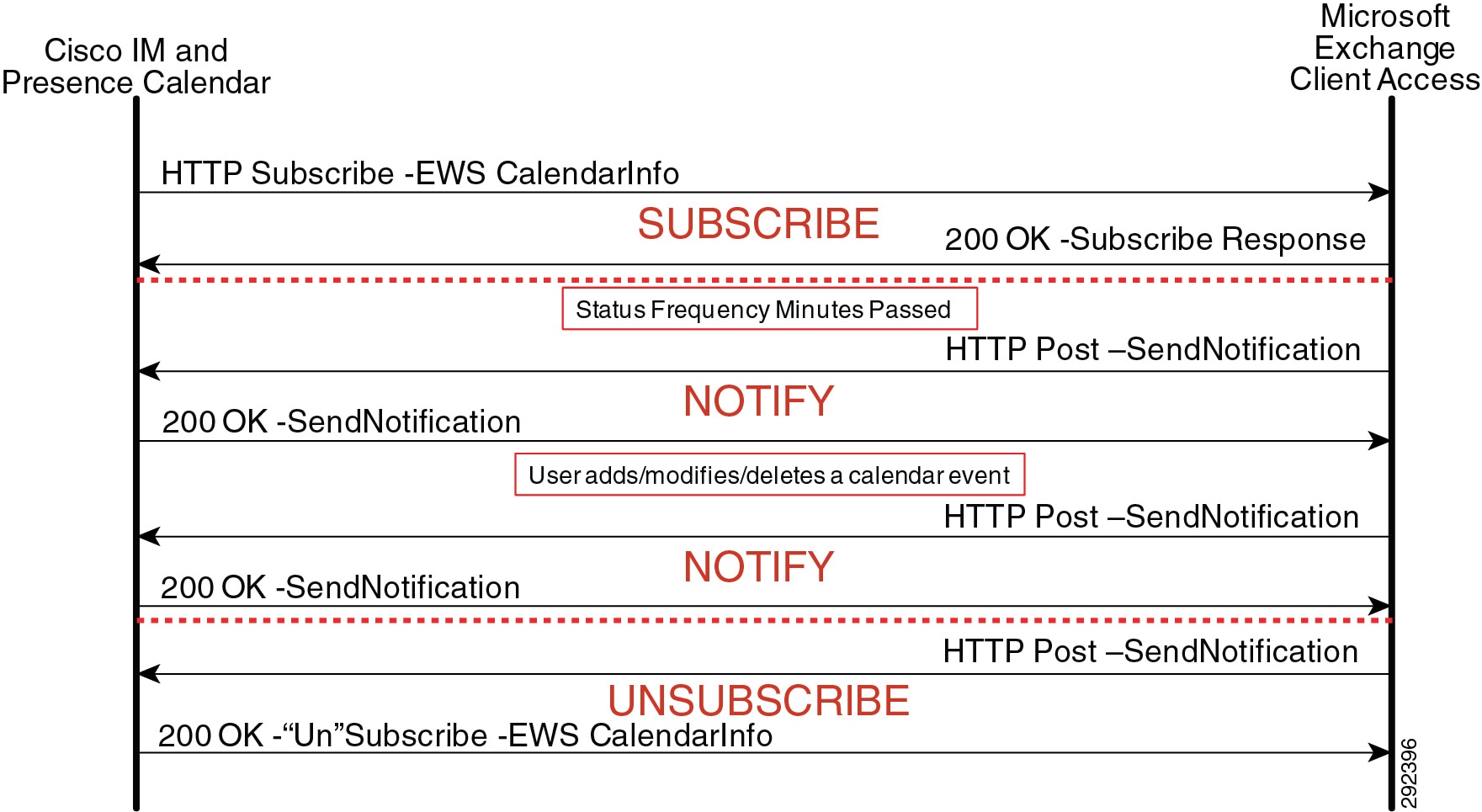
Exchange Web Services Auto Discover is also supported by Cisco IM and Presence if a service connection point (SCP) Active Directory object has been created for each server where the Client Access Server (CAS) role is installed. The calendar gateway is configured with Auto Discover using the domain and optionally the site instead of a host and port. Cisco IM and Presence uses the auto-discover algorithm to determine which Exchange Web Services URL to use in contacting the correct Client Access Server Exchange Server.
Cisco IM and Presence Mobility Integration
Cisco IM and Presence has the ability to integrate contact lists and presence state with Cisco Jabber Mobile IM. Jabber Mobile IM continues to communicate directly with Cisco Unified CM, while Cisco Unified CM communicates with Cisco IM and Presence via AXL/SOAP and SIP.
An application user must be configured on Cisco IM and Presence and Cisco Unified CM before Cisco Unified CM can establish an administrative session with Cisco IM and Presence. Cisco Jabber Mobile IM end-user logins will generate a Cisco Unified CM SOAP request to Cisco IM and Presence for system configuration, user configuration, contact list, presence rules, and application dial rules, followed by Unified Communicator Change Notifier (UCCN) configuration and Presence SIP subscriptions.
Cisco IM and Presence Third-Party Open API
Cisco IM and Presence has the ability to integrate with third-party applications through HTTP in addition to SIP/SIMPLE and XMPP. The HTTP interface has a configuration interface as well as a presence interface via Representational State Transfer (REST). The Third-Party Open API provides two mechanisms to access presence: a real-time eventing model and a polling model.
For more information on the Third-Party Open API, refer to the Cisco Developer Community at
http://developer.cisco.com/web/cdc
Real-Time Eventing Model
The real-time eventing model uses an application user on Cisco IM and Presence to establish an administrative session, which allows for end users to log in with that session key. Once the end user has logged in, the user registers and subscribes for presence updates using Representational State Transfer (REST). Figure 23-22 highlights the Third-Party Open API real-time eventing model interaction with Cisco IM and Presence.
Figure 23-22 Third-Party Open API Real-Time Eventing Model

The call flow in Figure 23-22 illustrates the following sequence of events:
1. ![]() The application initiates a SOAP login request to Cisco IM and Presence via the super-user application user (APIUser), and Cisco IM and Presence returns a session key. The application can then log in the end-user with this session key (essentially, the end-user logs in via the application).
The application initiates a SOAP login request to Cisco IM and Presence via the super-user application user (APIUser), and Cisco IM and Presence returns a session key. The application can then log in the end-user with this session key (essentially, the end-user logs in via the application).
2. ![]() The end user registers the endpoint using the application-user session key.
The end user registers the endpoint using the application-user session key.
3. ![]() The application initiates a subscribe request (using the session key) on behalf of the end user to retrieve user information, contact list, and presence rules.
The application initiates a subscribe request (using the session key) on behalf of the end user to retrieve user information, contact list, and presence rules.
4. ![]() Cisco IM and Presence sends a notification - unsecured.
Cisco IM and Presence sends a notification - unsecured.
5. ![]() The application requests the user's presence status.
The application requests the user's presence status.
Polling Model
The polling model uses an application user on Cisco IM and Presence to establish an administrative session, which allows for end users to log in with that session key. Once the end user has logged in, the application requests presence updates periodically, also using Representational State Transfer (REST). Figure 23-23 highlights the Third-Party Open API polling model interaction with Cisco IM and Presence.
Figure 23-23 Third-Party Open API Polling Model
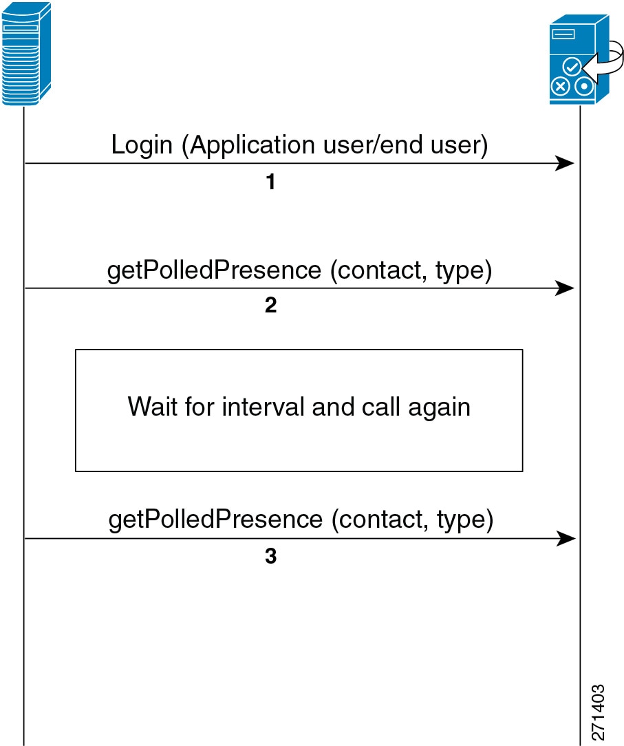
The call flow in Figure 23-23 illustrates the following sequence of events:
1. ![]() The application initiates a SOAP login request to Cisco IM and Presence via the super-user application user (APIUser), and Cisco IM and Presence returns a session key. The application can then log in the end-user with this session key (essentially, the end-user logs in via the application).
The application initiates a SOAP login request to Cisco IM and Presence via the super-user application user (APIUser), and Cisco IM and Presence returns a session key. The application can then log in the end-user with this session key (essentially, the end-user logs in via the application).
2. ![]() The application requests presence state and bypasses the eventing model.
The application requests presence state and bypasses the eventing model.
3. ![]() The application requests presence state and bypasses the eventing model.
The application requests presence state and bypasses the eventing model.
Note ![]() Both Basic presence and Rich presence can be retrieved; however, the polling model puts an additional load on the presence server.
Both Basic presence and Rich presence can be retrieved; however, the polling model puts an additional load on the presence server.
Extensible Messaging and Presence Protocol Interfaces
The Jabber XCP architecture allows for two additional open interfaces for presence, instant messaging, and roster management: a client XMPP interface and a Cisco AJAX XMPP Library interface. The client XMPP functionality enables third-party XMPP clients to integrate presence, instant messaging, and roster management, and it is a complementary interface to the SIP/SIMPLE interface on Cisco IM and Presence. The client XMPP interface is treated as a normal XMPP client within Cisco IM and Presence; therefore, sizing of the interface should be treated as a normal XMPP client.
The Cisco AJAX XMPP Library API provides a Web 2.0 style of interface to integrate Jabber XCP features into web applications and widgets, and it is made directly available from Cisco IM and Presence. The Cisco AJAX XMPP Library API is exclusively a client-side JavaScript library that communicates to the Bidirectional-streams Over Synchronous HTTP (BOSH) interface, which is essentially an XMPP over HTTP interface that allows the server to push data to a web browser through a long-polling technique.
Observe the following requirements when integrating either model of the Third-Party Open API with Cisco IM and Presence:
•![]() Certificates are required for the presence interface (sipproxy.der) and the configuration interface (tomcat_cert.der).
Certificates are required for the presence interface (sipproxy.der) and the configuration interface (tomcat_cert.der).
•![]() No more than 1000 Third-Party Open API users can be integrated per Cisco IM and Presence deployment.
No more than 1000 Third-Party Open API users can be integrated per Cisco IM and Presence deployment.
•![]() To improve performance, balance the Third-Party Open API users across all servers in the Cisco IM and Presence cluster.
To improve performance, balance the Third-Party Open API users across all servers in the Cisco IM and Presence cluster.
You can obtain additional information and support for use of the Cisco IM and Presence Third-Party Open API through Cisco Developer Services, available at:
http://developer.cisco.com/web/cupapi
Information and assistance for developers is also available from the Cisco Developer Community, which is accessible through valid Cisco login authentication at:
Design Considerations for Cisco IM and Presence
•![]() If LDAP integration is possible, LDAP synchronization with Unified CM should be used to pull all user information (number, ID, and so forth) from a single source. However, if the deployment includes both an LDAP server and Unified CM that does not have LDAP synchronization enabled, then the administrator should ensure consistent configuration across Unified CM and LDAP when configuring user directory number associations.
If LDAP integration is possible, LDAP synchronization with Unified CM should be used to pull all user information (number, ID, and so forth) from a single source. However, if the deployment includes both an LDAP server and Unified CM that does not have LDAP synchronization enabled, then the administrator should ensure consistent configuration across Unified CM and LDAP when configuring user directory number associations.
•![]() Cisco IM and Presence marks Layer 3 IP packets via Differentiated Services Code Point (DSCP). Cisco IM and Presence marks all call signaling traffic based on the Differential Service Value service parameter under SIP Proxy, which defaults to a value of DSCP 24 (PHB CS3).
Cisco IM and Presence marks Layer 3 IP packets via Differentiated Services Code Point (DSCP). Cisco IM and Presence marks all call signaling traffic based on the Differential Service Value service parameter under SIP Proxy, which defaults to a value of DSCP 24 (PHB CS3).
•![]() Presence Policy for Cisco IM and Presence is controlled strictly by a defined set of rules created by the user.
Presence Policy for Cisco IM and Presence is controlled strictly by a defined set of rules created by the user.
•![]() The Cisco IM and Presence publisher must be co-located with the Unified CM publisher.
The Cisco IM and Presence publisher must be co-located with the Unified CM publisher.
•![]() Use the service parameter CUP PUBLISH Trunk to streamline SIP communication traffic with the Cisco IM and Presence Service.
Use the service parameter CUP PUBLISH Trunk to streamline SIP communication traffic with the Cisco IM and Presence Service.
•![]() Associate presence users in Unified CM with a line appearance, rather than just a primary extension, to allow for increased granularity of device and user presence status. When using the service parameter CUP PUBLISH Trunk, you must associate presence users in Unified CM with a line appearance.
Associate presence users in Unified CM with a line appearance, rather than just a primary extension, to allow for increased granularity of device and user presence status. When using the service parameter CUP PUBLISH Trunk, you must associate presence users in Unified CM with a line appearance.
•![]() A Presence User Profile (the user activity and contact list contacts and size) must be taken into consideration for determining the server hardware and cluster topology characteristics.
A Presence User Profile (the user activity and contact list contacts and size) must be taken into consideration for determining the server hardware and cluster topology characteristics.
•![]() Use the User Assignment Mode sync agent parameter default of balanced for best overall cluster performance.
Use the User Assignment Mode sync agent parameter default of balanced for best overall cluster performance.
•![]() Cisco IM and Presence requires an external database instance for each server within in the cluster for persistent chat, and one database instance per cluster for message archiving and native compliance. The database instances can share the same hardware; however, the only external database supported is PostgreSQL.
Cisco IM and Presence requires an external database instance for each server within in the cluster for persistent chat, and one database instance per cluster for message archiving and native compliance. The database instances can share the same hardware; however, the only external database supported is PostgreSQL.
•![]() Cisco IM and Presence supports a total of 45,000 users per cluster for full Unified Communications mode or 75,000 users for IM-only mode. The sizing for users must take into account the number of SIP/SIMPLE users and the number of XMPP users. XMPP users have slightly better performance because SIP/SIMPLE users employ the IM Gateway functionality into the Jabber XCP architecture.
Cisco IM and Presence supports a total of 45,000 users per cluster for full Unified Communications mode or 75,000 users for IM-only mode. The sizing for users must take into account the number of SIP/SIMPLE users and the number of XMPP users. XMPP users have slightly better performance because SIP/SIMPLE users employ the IM Gateway functionality into the Jabber XCP architecture.
•![]() When migrating a Cisco IM and Presence deployment from version 7.x to 8.x, you must deactivate the presence engine service prior to the upgrade and re-enable it after all servers have been upgraded to 8.x.
When migrating a Cisco IM and Presence deployment from version 7.x to 8.x, you must deactivate the presence engine service prior to the upgrade and re-enable it after all servers have been upgraded to 8.x.
•![]() All eXtensible Communications Platform (XCP) communications and logging are stored in GMT and not localized to the installed location.
All eXtensible Communications Platform (XCP) communications and logging are stored in GMT and not localized to the installed location.
•![]() Cisco IM and Presence 9.x is compatible with Unified CM 9.x only.
Cisco IM and Presence 9.x is compatible with Unified CM 9.x only.
•![]() Cisco Business Edition 7.x and later releases support LDAP synchronization, which should be enabled when integrating Cisco Business Edition with Cisco IM and Presence.
Cisco Business Edition 7.x and later releases support LDAP synchronization, which should be enabled when integrating Cisco Business Edition with Cisco IM and Presence.
•![]() For ease of user migration and contact list migration, Cisco IM and Presence Bulk Administration Tool supports bulk contact list importation using a comma-separated value (csv) file as input for this bulk importation.
For ease of user migration and contact list migration, Cisco IM and Presence Bulk Administration Tool supports bulk contact list importation using a comma-separated value (csv) file as input for this bulk importation.
For a complete listing of ports used by Cisco IM and Presence, refer to Port Usage Information for Cisco IM and Presence, available at
http://www.cisco.com/en/US/products/ps6837/products_device_support_tables_list.html
Third-Party Presence Server Integration
Cisco IM and Presence provides an interface based on SIP and SIP for Instant Messaging and Presence Leveraging Extensions (SIMPLE) for integrating SIP and SIMPLE applications into the Cisco Unified Communications solution. You can configure and integrate a third-party presence server or application with this SIP/SIMPLE interface to provide presence aggregation and federation.
Microsoft Communications Server
For all setup, configuration, and deployment of Microsoft Live Communications Server 2005 or Office Communications Server 2007, Microsoft Lync, and Microsoft Office Communicator, refer to the documentation at:
Cisco does not provide configuration, deployment, or best practice procedures for Microsoft Communications products, but Cisco does provide the guidelines listed below for integrating Cisco IM and Presence with Microsoft Live Communications Server 2005 or Office Communications Server 2007 or Microsoft Lync.
Cisco Systems has developed an application note to show feature interoperability and configuration steps for integrating Cisco IM and Presence with Microsoft Live Communications Server 2005. You can access this application note at:
http://www.cisco.com/en/US/docs/voice_ip_comm/cucme/pbx/interop/notes/602270nt.pdf
Cisco Systems has also developed application notes to show feature interoperability and configuration steps for integrating Cisco IM and Presence with Microsoft Office Communications Server 2007 or Microsoft Lync. You can access the application notes at the following locations:
http://www.cisco.com/en/US/docs/voice_ip_comm/cucme/pbx/interop/notes/617030nt.pdf
http://www.cisco.com/en/US/solutions/collateral/ns340/ns414/ns728/ns784/712410.pdf
Cisco Systems has also developed a guide for integrating Cisco IM and Presence with Microsoft Office Communications Server 2007 or Microsoft Lync. This Integration Note for Configuring Cisco IM and Presence with Microsoft LCS/OCS for MOC Call Control is available at:
http://www.cisco.com/en/US/products/ps6837/products_installation_and_configuration_guides_list.html
Guidelines for Integrating Cisco IM and Presence with Microsoft Live Communications Server 2005 or Office Communications Server 2007
The following guidelines apply when integrating the Cisco IM and Presence Service and Microsoft Live Communications Server 2005 or Office Communications Server 2007 or Microsoft Lync:
•![]() Communications between Cisco IM and Presence and Microsoft Live Communications Server 2005 or Office Communications Server 2007 or Microsoft Lync uses the SIP/SIMPLE interface. However, Microsoft Live Communications Server 2005 or Office Communications Server 2007 or Microsoft Lync tunnels Computer-Supported Telecommunications Applications (CSTA) traffic over SIP. Therefore, the CTI gateway on the Cisco IM and Presence Service must be configured to handle the CSTA-to-CTI conversion for Click to Call phone control.
Communications between Cisco IM and Presence and Microsoft Live Communications Server 2005 or Office Communications Server 2007 or Microsoft Lync uses the SIP/SIMPLE interface. However, Microsoft Live Communications Server 2005 or Office Communications Server 2007 or Microsoft Lync tunnels Computer-Supported Telecommunications Applications (CSTA) traffic over SIP. Therefore, the CTI gateway on the Cisco IM and Presence Service must be configured to handle the CSTA-to-CTI conversion for Click to Call phone control.
•![]() Cisco IM and Presence deployment with Microsoft Office Communications Server 2007 or Live Communications Server 2005 or Microsoft Lync for Remote Call Control, should consist of a single subcluster pair of servers that make up the Cisco IM and Presence cluster.
Cisco IM and Presence deployment with Microsoft Office Communications Server 2007 or Live Communications Server 2005 or Microsoft Lync for Remote Call Control, should consist of a single subcluster pair of servers that make up the Cisco IM and Presence cluster.
•![]() The following table lists the number of users supported per platform.
The following table lists the number of users supported per platform.
|
|
|
|
|
|---|---|---|---|
MCS 7825, 7835, or 7845 |
MCS 7825-H4/I4 or earlier |
900 |
3,600 |
MCS 7825, 7835, or 7845 |
MCS 7825-H5/I5 or OVA equivalent servers |
1,000 |
4,000 |
MCS 7825, 7835, or 7845 |
MCS 7835-H2/I2 |
2,000 |
8,000 |
MCS 7825, 7835, or 7845 |
MCS 7835-H3/I3 or OVA equivalent servers |
2,500 |
10,000 |
MCS 7825, 7835, or 7845 |
MCS 7845-H2/I2 or OVA equivalent servers |
5,000 |
20,000 |
MCS 7825, 7835, or 7845 |
MCS 7845-I3 or OVA equivalent servers |
10,000 |
40,000 |
1 These numbers are based on Cisco Unified CM 7.1(3) and later releases. |
•![]() You must configure the same end-user ID in LDAP, Unified CM, and Microsoft Live Communications Server 2005 or Office Communications Server 2007 or Microsoft Lync. This practice avoids any conflicts between Microsoft Live Communications Server 2005 or Office Communications Server 2007 or Microsoft Lync authentication with Active Directory (AD) and the end-user configuration on Unified CM, as well as conflicts with user phone control on Unified CM.
You must configure the same end-user ID in LDAP, Unified CM, and Microsoft Live Communications Server 2005 or Office Communications Server 2007 or Microsoft Lync. This practice avoids any conflicts between Microsoft Live Communications Server 2005 or Office Communications Server 2007 or Microsoft Lync authentication with Active Directory (AD) and the end-user configuration on Unified CM, as well as conflicts with user phone control on Unified CM.
For Active Directory, Cisco recommends that the user properties of General, Account, and Live Communications all have the same ID. To ensure the Cisco IM and Presence users are consistent, LDAP Synchronization and Authentication should be enabled with Unified CM.
•![]() You must configure Microsoft Live Communications Server 2005 or Office Communications Server 2007 or Microsoft Lync Host Authentication to contain the Cisco IM and Presence publisher and subscriber.
You must configure Microsoft Live Communications Server 2005 or Office Communications Server 2007 or Microsoft Lync Host Authentication to contain the Cisco IM and Presence publisher and subscriber.
•![]() You can configure routing of the SIP messages to Cisco IM and Presence by means of Static Routes in the Microsoft Live Communications Server 2005 or Office Communications Server 2007 or Microsoft Lync properties.
You can configure routing of the SIP messages to Cisco IM and Presence by means of Static Routes in the Microsoft Live Communications Server 2005 or Office Communications Server 2007 or Microsoft Lync properties.
•![]() You must configure an incoming and outgoing access control list (ACL) on the Cisco IM and Presence Service to allow for communications with Microsoft Live Communications Server 2005 or Office Communications Server 2007 or Microsoft Lync.
You must configure an incoming and outgoing access control list (ACL) on the Cisco IM and Presence Service to allow for communications with Microsoft Live Communications Server 2005 or Office Communications Server 2007 or Microsoft Lync.
•![]() You must enable each user for use of Microsoft Office Communicator in the Cisco IM and Presence Service configuration, in addition to enabling each user for presence in Unified CM.
You must enable each user for use of Microsoft Office Communicator in the Cisco IM and Presence Service configuration, in addition to enabling each user for presence in Unified CM.
•![]() Take into account bandwidth considerations for Microsoft Office Communicator login due to the exchange of configuration information between Microsoft Office Communicator and the Microsoft Communications Server, and due to initial communication with the Cisco IM and Presence Service CTI gateway.
Take into account bandwidth considerations for Microsoft Office Communicator login due to the exchange of configuration information between Microsoft Office Communicator and the Microsoft Communications Server, and due to initial communication with the Cisco IM and Presence Service CTI gateway.
•![]() The parameters that are required for Microsoft Office Communications Server 2007 or Microsoft Lync have changed names from Live Communications Server 2005. The TEL URI parameter defined in Live Communications Server 2005 is the same as the Line URI parameter in Office Communications Server 2007 or Microsoft Lync, and the Remote Call Control SIP URI parameter defined in Live Communications Server 2005 is the same as the Server URI parameter in Office Communications Server 2007 or Microsoft Lync.
The parameters that are required for Microsoft Office Communications Server 2007 or Microsoft Lync have changed names from Live Communications Server 2005. The TEL URI parameter defined in Live Communications Server 2005 is the same as the Line URI parameter in Office Communications Server 2007 or Microsoft Lync, and the Remote Call Control SIP URI parameter defined in Live Communications Server 2005 is the same as the Server URI parameter in Office Communications Server 2007 or Microsoft Lync.
•![]() To address the issue of a reverse look-up of a directory number that corresponds to a user, use the guidelines documented in the Release Notes for Cisco IM and Presence, available at
To address the issue of a reverse look-up of a directory number that corresponds to a user, use the guidelines documented in the Release Notes for Cisco IM and Presence, available at
http://www.cisco.com/en/US/products/ps6837/prod_release_notes_list.html
IBM Lotus Sametime
Cisco Systems, Inc. provides the following guidelines around how best to integrate IBM Lotus Sametime Server with Cisco Unified Communications, but does not contend configuration, deployment, or best practice procedures for IBM Communications products.
For all setup, configuration, and deployment of IBM Lotus Sametime Server, refer to the documentation at
Cisco does not provide configuration, deployment, or best practice procedures for IBM communications products, but Cisco does provide the guidelines listed below for integrating IBM Lotus Sametime Server with a Cisco Unified Communications system.
Guidelines for Integrating Cisco IM and Presence with IBM Lotus Sametime Server (Version 7.5.1 and Later)
Click-to-call and click-to-conference functionality integrated within the IBM Lotus Sametime client is handled via a Cisco Call Control plugin resident on IBM Lotus Sametime Server. The integration into Cisco Unified Communications for click-to-call and click-to-conference functionality is handled via the SIP trunk interface with Unified CM. The integration into Cisco Unified Communications for presence functionality is handled via the SIP/SIMPLE interface with Cisco IM and Presence.
•![]() The Unified CM SIP trunk for click-to-call and click-to-conference functionality must be configured for out-of-dialog REFER processing. Enable the Accept Out-of-Dialog REFER checkbox in the SIP Trunk Security Profile associated with the SIP trunk communicating with IBM Lotus Sametime Server.
The Unified CM SIP trunk for click-to-call and click-to-conference functionality must be configured for out-of-dialog REFER processing. Enable the Accept Out-of-Dialog REFER checkbox in the SIP Trunk Security Profile associated with the SIP trunk communicating with IBM Lotus Sametime Server.
•![]() The Cisco Call Control plugin, resident on IBM Lotus Sametime Server, maintains a configured list of Unified CMs utilized in a round-robin manner. This list should be populated with the IP address of Unified CM subscribers that have been configured with the out-of-dialog REFER SIP trunks.
The Cisco Call Control plugin, resident on IBM Lotus Sametime Server, maintains a configured list of Unified CMs utilized in a round-robin manner. This list should be populated with the IP address of Unified CM subscribers that have been configured with the out-of-dialog REFER SIP trunks.
The Unified CM list can also be configured with DNS SRV; however, currently this SRV logic is used for redundancy only and not for load balancing, therefore it is not a recommended setting.
•![]() Deployment topologies using IBM Lotus Sametime Server typically will integrate with multiple Unified CM clusters due to the capacity differences between the two systems. With the Cisco Click-to-Call plugin utilizing a list of Unified CMs in a round-robin fashion, a call initiation can result in a REFER being sent to a cluster different from the user's home cluster. The Unified CM receiving this call setup will process the REFER and generate an INVITE to the appropriate destination to complete the call setup.
Deployment topologies using IBM Lotus Sametime Server typically will integrate with multiple Unified CM clusters due to the capacity differences between the two systems. With the Cisco Click-to-Call plugin utilizing a list of Unified CMs in a round-robin fashion, a call initiation can result in a REFER being sent to a cluster different from the user's home cluster. The Unified CM receiving this call setup will process the REFER and generate an INVITE to the appropriate destination to complete the call setup.
•![]() Traffic marking has not been implemented fully with the Cisco Call Control plugin. Therefore, follow the traffic marking guidelines in the Enterprise QoS Solution Reference Network Design (SRND), available at
Traffic marking has not been implemented fully with the Cisco Call Control plugin. Therefore, follow the traffic marking guidelines in the Enterprise QoS Solution Reference Network Design (SRND), available at
http://www.cisco.com/go/designzone
 Feedback